2004 SUBARU FORESTER power steering
[x] Cancel search: power steeringPage 1944 of 2870
FU(H4DOTC 2.5)-14
FUEL INJECTION (FUEL SYSTEM)
Intake Manifold
3. Intake Manifold
A: REMOVAL
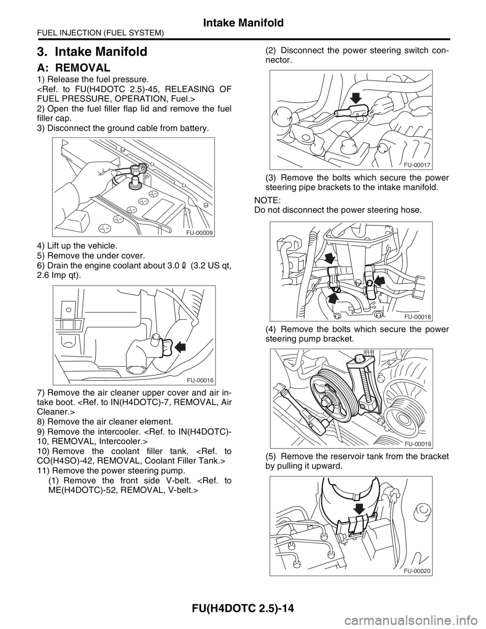
1) Release the fuel pressure.
2) Open the fuel filler flap lid and remove the fuel
filler cap.
3) Disconnect the ground cable from battery.
4) Lift up the vehicle.
5) Remove the under cover.
6) Drain the engine coolant about 3.02 (3.2 US qt,
2.6 Imp qt).
7) Remove the air cleaner upper cover and air in-
take boot.
8) Remove the air cleaner element.
9) Remove the intercooler.
10) Remove the coolant filler tank.
11) Remove the power steering pump.
(1) Remove the front side V-belt.
nector.
(3) Remove the bolts which secure the power
steering pipe brackets to the intake manifold.
NOTE:
Do not disconnect the power steering hose.
(4) Remove the bolts which secure the power
steering pump bracket.
(5) Remove the reservoir tank from the bracket
by pulling it upward.
FU-00009
FU-00016
FU-00017
FU-00018
FU-00019
FU-00020
Page 1945 of 2870
FU(H4DOTC 2.5)-15
FUEL INJECTION (FUEL SYSTEM)
Intake Manifold
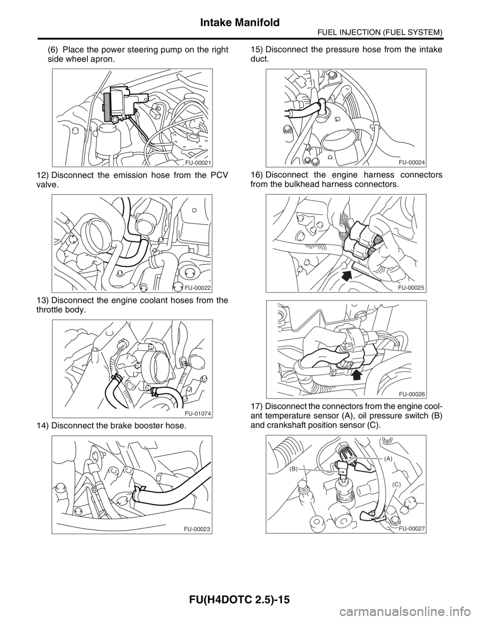
(6) Place the power steering pump on the right
side wheel apron.
12) Disconnect the emission hose from the PCV
valve.
13) Disconnect the engine coolant hoses from the
throttle body.
14) Disconnect the brake booster hose.15) Disconnect the pressure hose from the intake
duct.
16) Disconnect the engine harness connectors
from the bulkhead harness connectors.
17) Disconnect the connectors from the engine cool-
ant temperature sensor (A), oil pressure switch (B)
and crankshaft position sensor (C).
FU-00021
FU-00022
FU-01074
FU-00023
FU-00024
FU-00025
FU-00026
(A)
(B)
(C)
FU-00027
Page 1948 of 2870
FU(H4DOTC 2.5)-18
FUEL INJECTION (FUEL SYSTEM)
Intake Manifold
LH SIDE
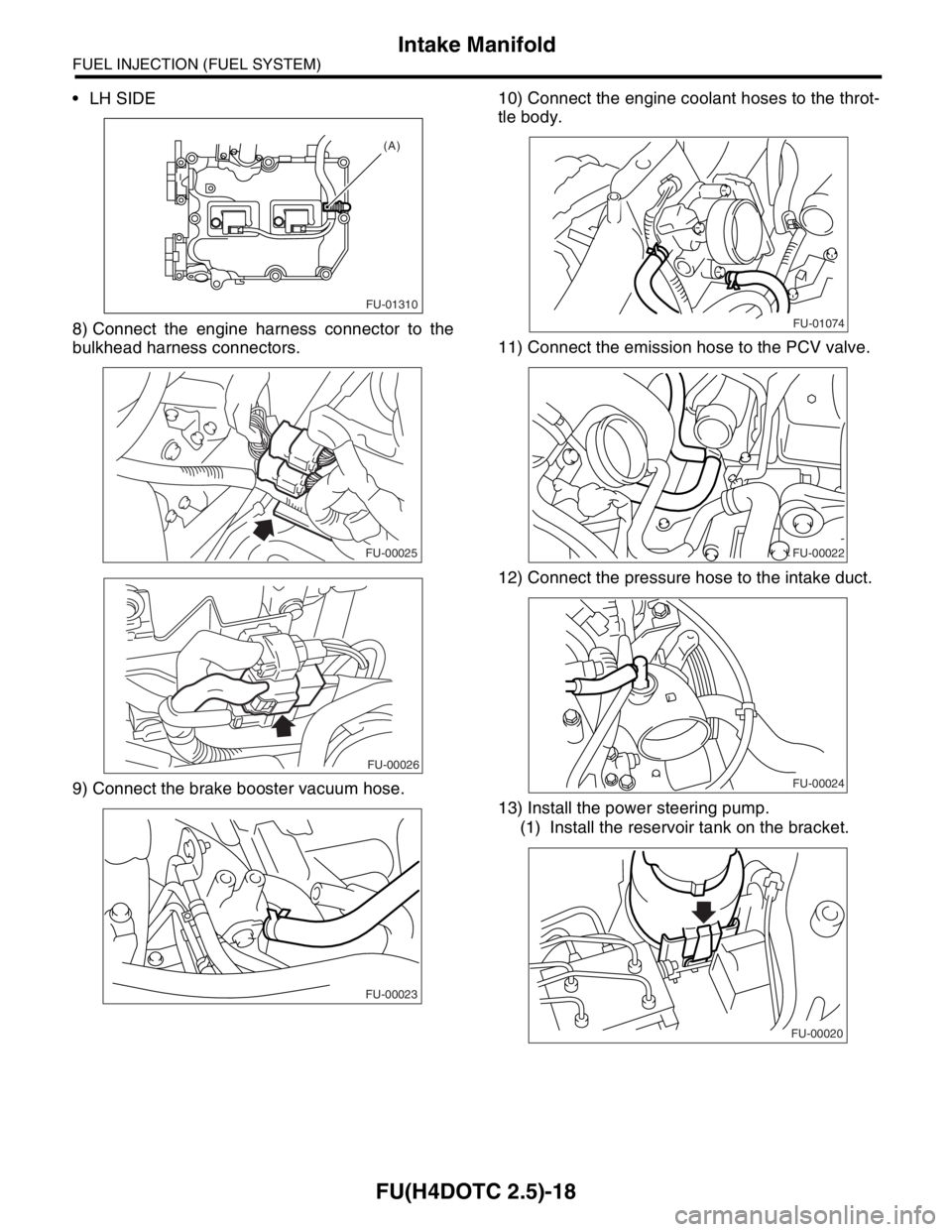
8) Connect the engine harness connector to the
bulkhead harness connectors.
9) Connect the brake booster vacuum hose.10) Connect the engine coolant hoses to the throt-
tle body.
11) Connect the emission hose to the PCV valve.
12) Connect the pressure hose to the intake duct.
13) Install the power steering pump.
(1) Install the reservoir tank on the bracket.
FU-01310
(A)
FU-00025
FU-00026
FU-00023
FU-01074
FU-00022
FU-00024
FU-00020
Page 1949 of 2870
FU(H4DOTC 2.5)-19
FUEL INJECTION (FUEL SYSTEM)
Intake Manifold
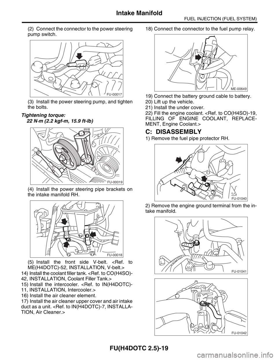
(2) Connect the connector to the power steering
pump switch.
(3) Install the power steering pump, and tighten
the bolts.
Tightening torque:
22 N·m (2.2 kgf-m, 15.9 ft-lb)
(4) Install the power steering pipe brackets on
the intake manifold RH.
(5) Install the front side V-belt.
14) Install the coolant filler tank.
15) Install the intercooler.
16) Install the air cleaner element.
17) Install the air cleaner upper cover and air intake
duct as a unit.
19) Connect the battery ground cable to battery.
20) Lift up the vehicle.
21) Install the under cover.
22) Fill the engine coolant.
MENT, Engine Coolant.>
C: DISASSEMBLY
1) Remove the fuel pipe protector RH.
2) Remove the engine ground terminal from the in-
take manifold.
FU-00017
FU-00019
FU-00018
ME-00649
FU-01040
FU-01041
FU-01042
Page 2029 of 2870
EN(H4DOTC 2.5)-5
ENGINE (DIAGNOSTIC)
General Description
3. General Description
A: CAUTION
1) Airbag system wiring harness is routed near the
ECM, main relay and fuel pump relay.
CAUTION:
All airbag system wiring harness and con-
nectors are all colored yellow. Do not use the
electrical test equipment on these circuits.
Be careful not to damage the Airbag system
wiring harness when servicing the ECM, TCM,
main relay and fuel pump relay.
2) Never connect the battery in reverse polarity.
The ECM will be destroyed immediately.
The fuel injector and other part will be damaged.
3) Do not disconnect the battery terminals while the
engine is running.
A large counter electromotive force will be gener-
ated in the generator, and this voltage may damage
electronic parts such as ECM, etc.
4) Before disconnecting the connectors of each
sensor and the ECM, be sure to turn OFF the igni-
tion switch.
5) Poor contact has been identified as a primary
cause of this problem. Measure the voltage or re-
sistance of individual sensor or all electrical control
modules using a tapered pin with a diameter of less
than 0.64 mm (0.025 in). Do not insert the pin more
than 5 mm (0.20 in) into the part.
6) Remove the ECM from the located position after
disconnecting two cables on battery.
Otherwise, the ECM may be damaged.
CAUTION:
When replacing the ECM, be careful not to use
the wrong spec. ECM to avoid damaging the
fuel injection system.
7) Connectors to each sensor in the engine com-
partment and the harness connectors on the en-
gine side and body side are all designed to be
waterproof. However, take care not to allow water
to get into the connectors when washing the vehi-
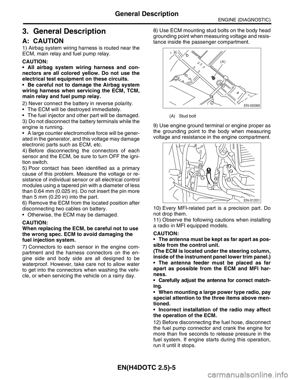
cle, or when servicing the vehicle on a rainy day. 8) Use ECM mounting stud bolts on the body head
grounding point when measuring voltage and resis-
tance inside the passenger compartment.
9) Use engine ground terminal or engine proper as
the grounding point to the body when measuring
voltage and resistance in the engine compartment.
10) Every MFI-related part is a precision part. Do
not drop them.
11) Observe the following cautions when installing
a radio in MFI equipped models.
CAUTION:
The antenna must be kept as far apart as pos-
sible from the control unit.
(The ECM is located under the steering column,
inside of the instrument panel lower trim panel.)
The antenna feeder must be placed as far
apart as possible from the ECM and MFI har-
ness.
Carefully adjust the antenna for correct match-
ing.
When mounting a large power type radio, pay
special attention to the three items above men-
tioned.
Incorrect installation of the radio may affect
the operation of the ECM.
12) Before disconnecting the fuel hose, disconnect
the fuel pump connector and crank the engine for
more than five seconds to release pressure in the
fuel system. If engine starts during this operation,
run it until it stops.
(A) Stud bolt
EN-00069
(A)
EN-01201
Page 2043 of 2870

EN(H4DOTC 2.5)-19
ENGINE (DIAGNOSTIC)
Engine Control Module (ECM) I/O Signal
Radiator fan relay 2 con-
trolB135 24ON: 0.5, or less
OFF: 10 — 13ON: 0.5, or less
OFF: 13 — 14Model with A/C only
Malfunction indicator
lightB134 17 — —Light “ON”: 1, or less
Light “OFF”: 10 — 14
Engine speed output B134 23 — 0 — 13, or more Waveform
Purge control solenoid
valveB134 14ON: 1, or less
OFF: 10 — 13ON: 1, or less
OFF: 13 — 14Wavefor m
Manifold
absolute
pressure
sensorSignal B136 22 1.7 — 2.4 1.1 — 1.6
— Pow er
supplyB136 16 5 5
GND
(sensors)B136 35 0 0
Small light switch B137 12ON: 0
OFF: 10 — 13ON: 0
OFF: 13 — 14—
Blower fan switch B137 13ON: 0
OFF: 10 — 13ON: 0
OFF: 13 — 14—
Rear defogger switch B137 11ON: 0
OFF: 10 — 13ON: 0
OFF: 13 — 14—
Power steering oil pres-
sure switchB137 10 10 — 13ON: 0
OFF: 13 — 14—
Front oxygen (A/F) sen-
sor signal (+)B134 33 2.8 — 3.2 2.8 — 3.2 —
Front oxygen (A/F) sen-
sor signal (−)B134 26 2.4 — 2.7 2.4 — 2.7 —
Front oxygen (A/F) sen-
sor shieldB134 25 0 0 —
SSM/GST communica-
tion lineB137 20 1 ← → 41 ← → 4—
GND (injector) B137 7 0 0 —
GND (ignition system) B135 12 0 0 —
GND (power supply)B135 4 0 0 —
B135 1 0 0 —
GND (control system)B137 1 0 0 —
B137 2 0 0 —
GND (Front oxygen (A/F)
sensor heater 1)B134 7 0 0 —
GND (Front oxygen (A/F)
sensor heater 2)B134 6 0 0 —
Camshaft position sen-
sor (LH)B135 8 0 — 0.9ON: 0
OFF: 4.7 — 5.3Wavefor m
Camshaft position sen-
sor (RH)B135 9 0 — 0.9ON: 0
OFF: 4.7 — 5.3Wavefor m
Fuel level sensor B136 20 0.12 — 4.75 0.12 — 4.75 —
Electronic
throttle
controlMain B136 180.64 — 0.72
Fully opens:
3.960.64 — 0.72
(After engine is
warmed-up.)Fully closed: 0.6 Fully opens:
3.96
Sub B136 291.51 — 1.58
Fully opens:
4.171.51 — 1.58
(After engine is
warmed-up)Fully closed: 1.48 Fully opens:
4.17
Pow er
supplyB136 16 5 5 —
GND
(sensor)B137 3 0 0 — DESCRIPTION Connector No. Terminal No.Signal (V)
NOTE
Ignition SW ON
(engine OFF)Engine ON
(Idling)
Page 2053 of 2870

EN(H4DOTC 2.5)-29
ENGINE (DIAGNOSTIC)
Subaru Select Monitor
NOTE:
For detailed operation procedure, refer to the “SUBARU SELECT MONITOR OPERATION MANUAL”.
Mass air flow sensor signal Air Flow Sensor Voltage V
AT/MT identification signal AT Vehicle ID Signal ON or OFF
ETC motor relay ETC Motor Relay ON or OFF
Clutch SW Clutch Switch ON or OFF
Stop Light SW Stop Light Switch ON or OFF
SET/COAST SW SET/COAST Switch ON or OFF
RESUME/ACCEL SW RESUME/ACCEL Switch ON or OFF
Brake SW Brake Switch ON or OFF
Main SW Main Switch ON or OFF
Ignition switch signal Ignition Switch ON or OFF
Test Mode Signal Test Mode Signal ON or OFF
Neutral position switch signal Neutral Position Switch ON or OFF
Air conditioning switch signal A/C Switch ON or OFF
Air conditioning signal A/C Compressor Signal ON or OFF
Radiator main fan relay signal Radiator Fan Relay #1 ON or OFF
Knocking signal Knocking Signal ON or OFF
Radiator sub fan relay signal Radiator Fan Relay #2 ON or OFF
Power steering switch signal P/S Switch ON or OFF
Rear oxygen sensor rich signalRear O
2 Rich Signal
ON or OFF
Starter switch signal Starter Switch ON or OFF
Idle switch signal Idle Switch Signal ON or OFF
Crankshaft position sensor signal Crankshaft Position Sig. ON or OFF
Camshaft position sensor signal Camshaft Position Sig. ON or OFF
Rear defogger switch signal Rear Defogger SW ON or OFF
Blower fan switch signal Blower Fan SW ON or OFF
Small light switch signal Light Switch ON or OFF
Handle switch signal Handle Switch —
Wiper switch signal Wiper Switch ON or OFF
A/C mid pressure switch signal A/C mid Pressure Switch ON or OFF
AT coordinate retard angle demand Retard Signal form AT ON or OFF
AT coordinate fuel cut demand Fuel Cut Signal from AT ON or OFF
AT coordinate permission signal Torque Permission Signal ON or OFF
UDC not torque down output Ban of Torque Down ON or OFF
UDC torque down demand Request Torque Down UDC ON or OFF
Tumble generated valve output signal TGV Output ON or OFF
Tumble generated valve drive signal TGV Drive OPEN or CLOSERemarks Display Unit of measure
Page 2056 of 2870
![SUBARU FORESTER 2004 Service Repair Manual EN(H4DOTC 2.5)-32
ENGINE (DIAGNOSTIC)
Subaru Select Monitor
7. LED OPERATION MODE FOR ENGINE
1) On the «Main Menu» display screen, select the {Each System Check} and press the [YES] key.
2) On the Â](/manual-img/17/57426/w960_57426-2055.png "SUBARU FORESTER 2004 Service Repair Manual EN(H4DOTC 2.5)-32
ENGINE (DIAGNOSTIC)
Subaru Select Monitor
7. LED OPERATION MODE FOR ENGINE
1) On the «Main Menu» display screen, select the {Each System Check} and press the [YES] key.
2) On the Â")
EN(H4DOTC 2.5)-32
ENGINE (DIAGNOSTIC)
Subaru Select Monitor
7. LED OPERATION MODE FOR ENGINE
1) On the «Main Menu» display screen, select the {Each System Check} and press the [YES] key.
2) On the «System Selection Menu» display screen, select the {Engine} and press the [YES] key.
3) Press the [YES] key after the information of engine type was displayed.
4) On the «Engine Diagnosis» screen, select the {Current Data Display/Save}, and then press the [YES] key.
5) On the «Data Display» screen, select the {Data & LED Display} and press the [YES] key.
6) Using the scroll key, move the display screen up or down until the desired data is shown.
A list of the support data is shown in the following table.
Description Display Message LED “ON” requirements
Ignition switch signal Ignition Switch ON or OFF When ignition switch is ON.
Test Mode Signal Test Mode Signal ON or OFF When test mode connector is connected.
Neutral position switch signal Neutral Position Switch ON or OFF When neutral position signal is entered.
Air conditioning switch signal A/C Switch ON or OFF When air conditioning switch is ON.
Air conditioning relay signal A/C Compressor Signal ON or OFF When air conditioning relay is in function.
Radiator main fan relay signal Radiator Fan Relay #1 ON or OFF When radiator main fan relay is in function.
Knocking signal Knocking Signal ON or OFF When knocking signal is input.
Radiator sub fan relay signal Radiator Fan Relay #2 ON or OFF When radiator sub fan relay is in function.
Rear oxygen sensor rich signalRear O
2 Rich Signal
ON or OFFWhen rear oxygen sensor mixture ratio is
rich.
Starter switch signal Starter Switch Signal ON or OFF When starter switch signal is entered.
Idle switch signal Idle Switch Signal ON or OFF When idle switch signal is entered.
Crankshaft position sensor signal Crankshaft Position Signal ON or OFFWhen crankshaft position sensor signal is
input.
Camshaft position sensor signal Camshaft Position Signal ON or OFFWhen camshaft position sensor signal is
entered.
Power steering switch signal P/S Switch ON or OFF When power steering switch is entered.
Rear defogger switch signal Rear Defogger Switch ON or OFF When rear defogger switch is ON.
Blower fan switch signal Blower Fan Switch ON or OFF When blower fan switch is ON.
Small light switch signal Light Switch ON or OFF When small light switch is ON.
Tumble generated valve actuator
signalTGV Output ON or OFF When TGV actuator signal is entered.
Tumble generated valve drive sig-
nalTGV DriveClose or
OpenWhen TGV moves and valve opens.
Handle switch signal Handle SWLow Input
or High
InputIlluminates in Low Input.
AT/MT identification terminal AT Vehicle ID Signal ON or OFF ON (AT model).
Wiper switch signal Wiper Switch ON or OFF When wiper switch is turned to ON.
A/C mid pressure switch signal A/C Mid Pressure Switch ON or OFFWhen A/C mid pressure switch is turned to
ON.
AT coordinate retard angle
demandRetard Signal from AT ON or OFF When AT retard angle signal is exists.
AT coordinate fuel cut demand Fuel Cut Signal from AT ON or OFFWhen AT coordinate fuel cut demand signal
is exists.
AT coordinate permission signal Torque Permission Signal ON or OFFWhen AT coordinate permission signal is
exists.
VDC not torque down out put Ban of Torque Down ON or OFFWhen VDC not torque down output signal is
exists.
VDC torque down demand Request Torque Down VDC ON or OFFWhen VDC torque down demand signal is
exists.
ETC motor relay signal ETC Motor Relay ON or OFFWhen electronic throttle control relay is in
function.
Clutch switch signal Clutch Switch ON or OFF When clutch switch is ON.
Stop switch signal Stop Light Switch ON or OFF When stop light switch is ON.