Page 564 of 2870
CC-12
CRUISE CONTROL SYSTEM
Inhibitor Switch (AT model)
8. Inhibitor Switch (AT model)
A: REMOVAL
1) Disconnect the ground cable from battery.
2) Disconnect the connector from inhibitor switch,
and then remove the switch.
MOVAL, Inhibitor Switch.>
B: INSTALLATION
Install in the reverse order of removal.
C: INSPECTION
Measure the inhibitor switch resistance.
If NG, replace the inhibitor switch.
Selector lever
positionTerminal No. Standard
P
7 and 12Less than 1 Ω
N Less than 1 Ω
Except P and N More than 1 MΩ
CC-00024
123456789101112
Page 565 of 2870
CC-13
CRUISE CONTROL SYSTEM
Neutral Position Switch (MT model)
9. Neutral Position Switch (MT
model)
A: REMOVAL
1) Disconnect the ground cable from battery.
2) Disconnect the connector from neutral position
switch, and then remove the switch.
43, BACK-UP LIGHT AND NEUTRAL POSITION
SWITCH, REMOVAL, Switches and Harness.>
B: INSTALLATION
Install in the reverse order of removal.
C: INSPECTION
Measure the neutral position switch resistance.
Non-turbo model
Turbo model
If NG, replace the neutral position switch.
Gear shift position Terminal No. Specified resistance
Neutral position
1 and 2Less than 1 Ω
Other positions More than 1 MΩ
Gear shift position Terminal No. Specified resistance
Neutral position
1 and 3Less than 1 Ω
Other positions More than 1 MΩ
MT-00110
1 2
MT-00111
1 2
3 4
Page 566 of 2870
CC-14
CRUISE CONTROL SYSTEM
Neutral Position Switch (MT model)
Page 568 of 2870
2004 FORESTER SERVICE MANUAL QUICK REFERENCE INDEX
BODY SECTION
G8080GE7
CRUISE CONTROL SYSTEM CC
CRUISE CONTROL SYSTEM
(DIAGNOSTIC)CC(H4SO)
CRUISE CONTROL SYSTEM
(DIAGNOSTIC)CC(H4DOTC)
CRUISE CONTROL SYSTEM
(DIAGNOSTIC)CC(H4DOTC 2.5)
IMMOBILIZER (DIAGNOSTIC) IM
Page 569 of 2870
CRUISE CONTROL SYSTEM
(DIAGNOSTIC)
CC(H4SO)
Page
1. Basic Diagnostic Procedure ........................................................................2
2. General Description ....................................................................................4
3. Electrical Components Location..................................................................6
4. Cruise Control Module I/O Signal................................................................7
5. Subaru Select Monitor.................................................................................9
6. Diagnostic Procedure with Symptom ........................................................11
7. List of Diagnostic Trouble Code (DTC) .....................................................27
8. Diagnostic Procedure with Diagnostic Trouble Code (DTC) .....................29
Page 570 of 2870

CC(H4SO)-2
CRUISE CONTROL SYSTEM (DIAGNOSTIC)
Basic Diagnostic Procedure
1. Basic Diagnostic Procedure
A: PROCEDURE
Step Check Yes No
1 START DIAGNOSIS.
1) Perform the pre-inspection.
CC(H4SO)-5, INSPECTION, General Descrip-
tion.>
2) Check the cruise control main switch opera-
tion.Is the cruise control main
switch turned ON?Go to step 2.Go to symptom 1.
CC(H4SO)-11,
SYMPTOM
CHART, Diagnos-
tic Procedure with
Symptom.>
2 PREPARE SUBARU SELECT MONITOR.Is Subaru Select Monitor avail-
able?Go to step 3.Go to step 4.
3 PERFORM CRUISE CANCEL CONDITIONS
DIAGNOSIS.
Perform the cruise cancel conditions diagno-
sis.
itor.>Is DTC indicated? Go to “List of Diag-
nostic Trouble
Code (DTC)”.
CC(H4SO)-27, List
of Diagnostic Trou-
ble Code (DTC).>Go to step 4.
4 CHECK CRUISE CONTROL SET OPERA-
TION.
Check the cruise control set operation. Can the cruise control be set
while driving at 40 km/h (25
MPH)? Go to step 5.Go to symptom 2.
CC(H4SO)-11,
SYMPTOM
CHART, Diagnos-
tic Procedure with
Symptom.>
5 CHECK VEHICLE SPEED IS HELD WITHIN
SET SPEED.
Make sure the vehicle speed is held within set
speed.Is the vehicle speed held within
set speed ±3 km/h (±2 MPH)? Go to step 6.Go to symptom 3.
CC(H4SO)-11,
SYMPTOM
CHART, Diagnos-
tic Procedure with
Symptom.>
6 CHECK RESUME/ACCEL OPERATION.
Check the RESUME/ACCEL operation. Does the vehicle speed
increase or return to set speed
after RESUME/ACCEL switch
has been pressed? Go to step 7.Go to symptom 4.
CC(H4SO)-11,
SYMPTOM
CHART, Diagnos-
tic Procedure with
Symptom.>
7 CHECK SET/COAST OPERATION.
Check the SET/COAST operation. Does the vehicle speed
decrease after SET/COAST
switch has been pressed? Go to step 8.Go to symptom 5.
CC(H4SO)-11,
SYMPTOM
CHART, Diagnos-
tic Procedure with
Symptom.>
8 CHECK CANCEL OPERATION.
Check the CANCEL operation. Is the cruise control released
after CANCEL switch has been
pressed?Go to step 9.Go to symptom 6.
CC(H4SO)-11,
SYMPTOM
CHART, Diagnos-
tic Procedure with
Symptom.>
Page 571 of 2870
CC(H4SO)-3
CRUISE CONTROL SYSTEM (DIAGNOSTIC)
Basic Diagnostic Procedure
9 CHECK CRUISE CONTROL RELEASE OP-
ERATION.
Check the cruise control release operation.Is the cruise control released
after brake pedal has been
depressed?Go to step 10.Go to symptom 7.
CC(H4SO)-11,
SYMPTOM
CHART, Diagnos-
tic Procedure with
Symptom.>
10 CHECK CRUISE CONTROL RELEASE OP-
ERATION.
Check the cruise control release operation. Is the cruise control released
after clutch pedal has been
depressed? (MT model) Finish the diag-
nostics. Go to symptom 8.
CC(H4SO)-11,
SYMPTOM
CHART, Diagnos-
tic Procedure with
Symptom.> Step Check Yes No
Page 572 of 2870

CC(H4SO)-4
CRUISE CONTROL SYSTEM (DIAGNOSTIC)
General Description
2. General Description
A: CAUTION
1. SUPPLEMENTAL RESTRAINT SYSTEM
AIRBAG
Airbag system wiring harness is routed near the
cruise control module and cruise control command
switch.CAUTION:
All airbag system wiring harness and connec-
tors are colored yellow. Do not use electrical test
equipment on these circuits.
Be careful not to damage the airbag system
wiring harness when servicing the cruise con-
trol module and cruise control command switch.
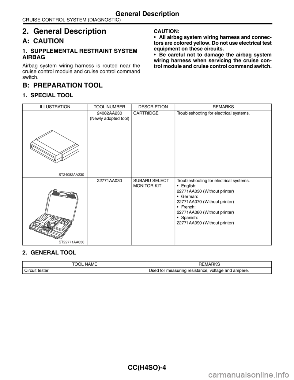
B: PREPARATION TOOL
1. SPECIAL TOOL
2. GENERAL TOOL
ILLUSTRATION TOOL NUMBER DESCRIPTION REMARKS
24082AA230
(Newly adopted tool)CARTRIDGE Troubleshooting for electrical systems.
22771AA030 SUBARU SELECT
MONITOR KITTroubleshooting for electrical systems.
English:
22771AA030 (Without printer)
German:
22771AA070 (Without printer)
French:
22771AA080 (Without printer)
Spanish:
22771AA090 (Without printer)
TOOL NAME REMARKS
Circuit tester Used for measuring resistance, voltage and ampere.
ST24082AA230
ST22771AA030