Page 2839 of 2870
CLUTCH SYSTEM
General Description
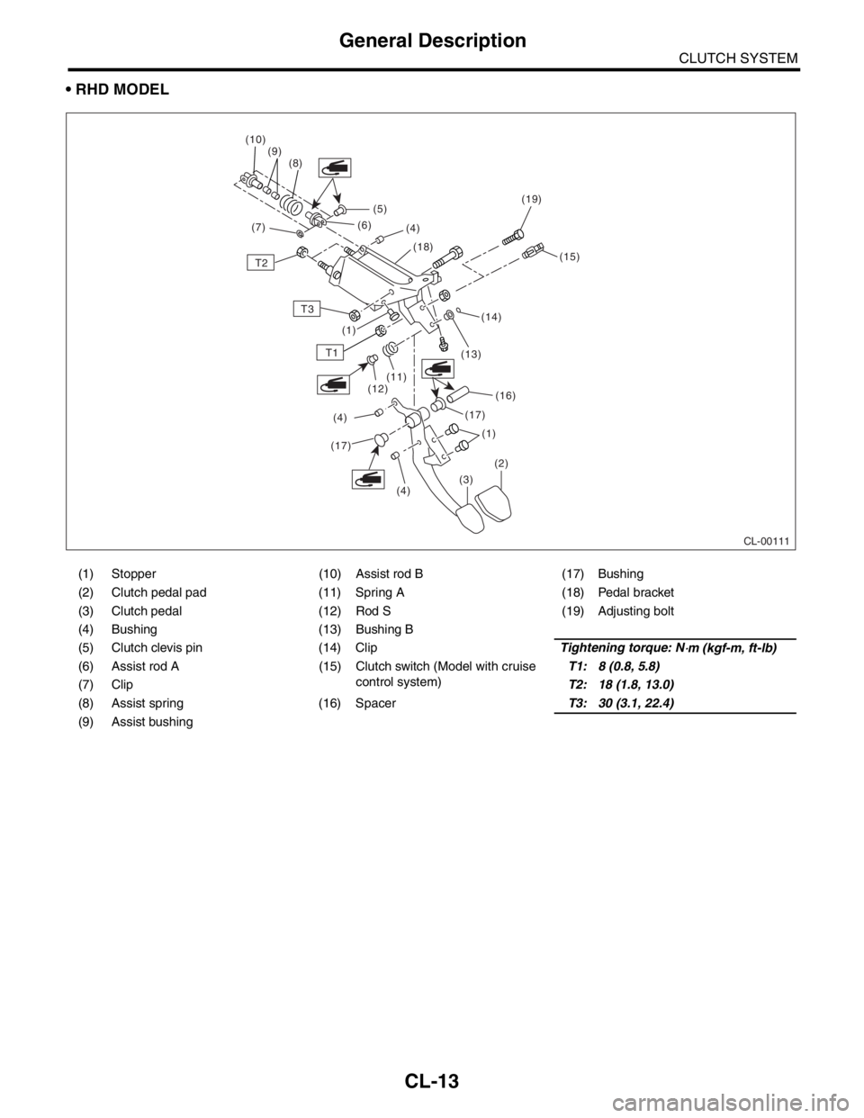
RHD MODEL
(1) Stopper (10) Assist rod B (17) Bushing
(2) Clutch pedal pad (11) Spring A (18) Pedal bracket
(3) Clutch pedal (12) Rod S (19) Adjusting bolt
(4) Bushing (13) Bushing B
(5) Clutch clevis pin (14) ClipTightening torque: N
⋅m (kgf-m, ft-lb)
(6) Assist rod A (15) Clutch switch (Model with cruise control system)T1: 8 (0.8, 5.8)
(7) Clip T2: 18 (1.8, 13.0)
(8) Assist spring (16) Spacer T3: 30 (3.1, 22.4)
(9) Assist bushing
CL-00111
(5)
T2
T3
T1
(16)
(13)
(14) (15)
(18)
(4)
(6)
(8)
(9)
(10)
(7)
(17)(1)
(1)
(2)
(3)
(4)
(17)
(4) (12)
(11)
(19)
CL-13
Page 2840 of 2870

CL-14
CLUTCH SYSTEM
General Description
C: CAUTION
Wear working clothing, including a cap, protec-
tive goggles, and protective shoes during opera-
tion.
Remove contamination including dirt and corro-
sion before removal, installation or disassembly.
Keep the disassembled parts in order and pro-
tect them from dust or dirt.
Before removal, installation or disassembly, be
sure to clarify the failure. Avoid unnecessary re-
moval, installation, disassembly, and replacement.
Be careful not to burn yourself, because each
part on the vehicle is hot after running.
Use SUBARU genuine fluid, grease etc. or the
equivalent. Do not mix fluid, grease etc. with that of
another grade or from other manufacturers.
Be sure to tighten fasteners including bolts and
nuts to the specified torque.
Place shop jacks or rigid racks at the specified
points.
Apply grease onto sliding or revolution surfaces
before installation.
Before installing O-rings or snap rings, apply suf-
ficient amount of fluid to avoid damage and defor-
mation.
Before securing a part on a vise, place cushion-
ing material such as wood blocks, aluminum plate,
or shop cloth between the part and the vise.
Keep fluid away from the vehicle body. If any flu-
id contacts the vehicle body, immediately flush the
area with water.
Page 2841 of 2870
CL-15
CLUTCH SYSTEM
General Description
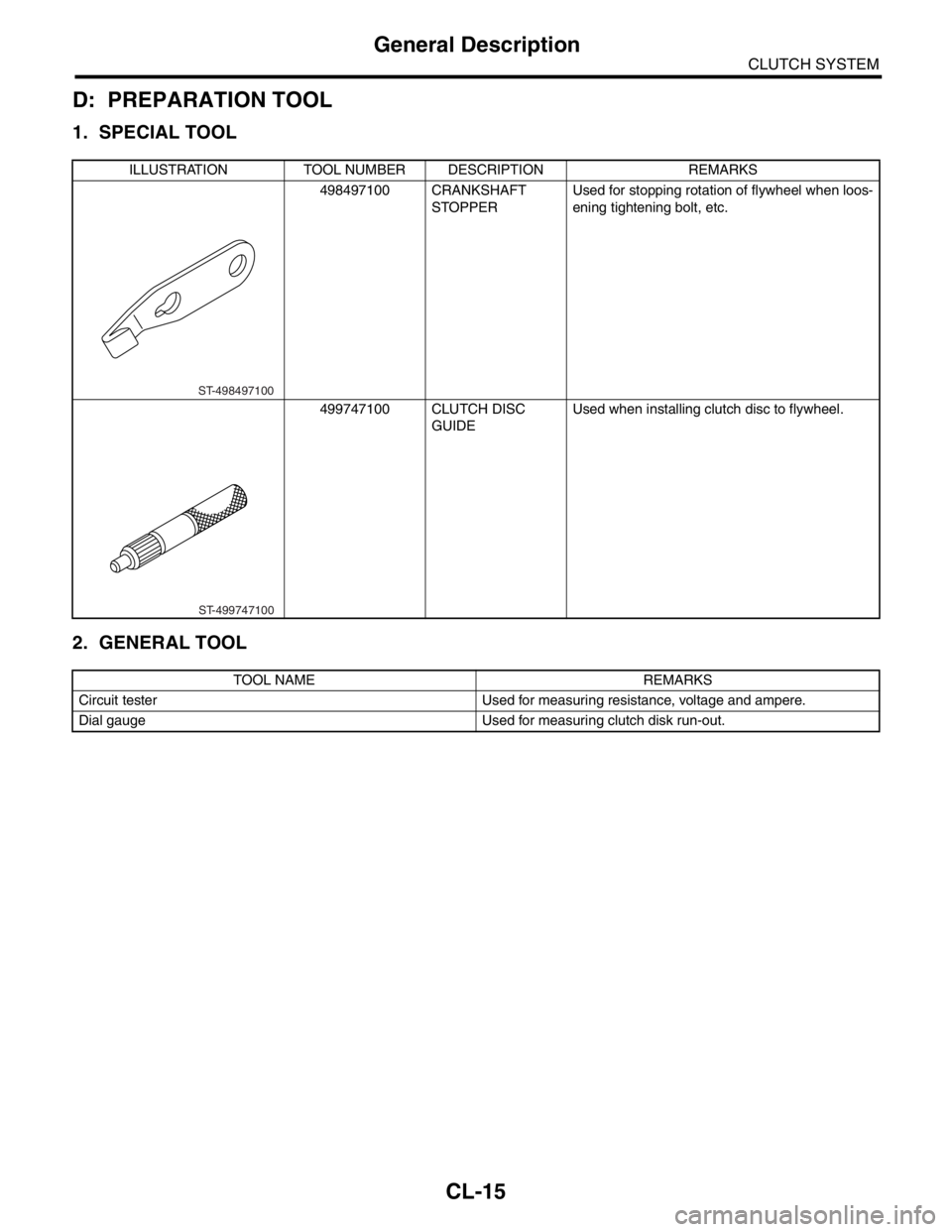
D: PREPARATION TOOL
1. SPECIAL TOOL
2. GENERAL TOOL
ILLUSTRATION TOOL NUMBER DESCRIPTION REMARKS
498497100 CRANKSHAFT
STOPPER Used for stopping rotation of flywheel when loos-
ening tightening bolt, etc.
499747100 CLUTCH DISC
GUIDEUsed when installing clutch disc to flywheel.
TOOL NAME REMARKS
Circuit tester Used for measuring resistance, voltage and ampere.
Dial gauge Used for measuring clutch disk run-out.
ST-498497100
ST-499747100
Page 2842 of 2870
CL-16
CLUTCH SYSTEM
Clutch Disc and Cover
2. Clutch Disc and Cover
A: REMOVAL
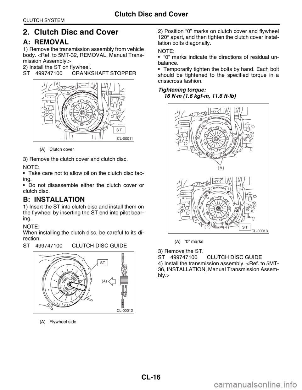
1) Remove the transmission assembly from vehicle
body.
mission Assembly.>
2) Install the ST on flywheel.
ST 499747100 CRANKSHAFT STOPPER
3) Remove the clutch cover and clutch disc.
NOTE:
Take care not to allow oil on the clutch disc fac-
ing.
Do not disassemble either the clutch cover or
clutch disc.
B: INSTALLATION
1) Insert the ST into clutch disc and install them on
the flywheel by inserting the ST end into pilot bear-
ing.
NOTE:
When installing the clutch disc, be careful to its di-
rection.
ST 499747100 CLUTCH DISC GUIDE2) Position “0” marks on clutch cover and flywheel
120° apart, and then tighten the clutch cover instal-
lation bolts diagonally.
NOTE:
“0” marks indicate the directions of residual un-
balance.
Temporarily tighten the bolts by hand. Each bolt
should be tightened to the specified torque in a
crisscross fashion.
Tightening torque:
16 N
⋅m (1.6 kgf-m, 11.6 ft-lb)
3) Remove the ST.
ST 499747100 CLUTCH DISC GUIDE
4) Install the transmission assembly.
36, INSTALLATION, Manual Transmission Assem-
bly.>
(A) Clutch cover
(A) Flywheel side
CL-00011
(A)
ST
CL-00012
(A)
ST
(A) “0” marks
CL-00013 (A)ST(2)
(5)
(3)(1)
(6)
(4)
Page 2843 of 2870
CL-17
CLUTCH SYSTEM
Clutch Disc and Cover
C: INSPECTION
1. CLUTCH DISC
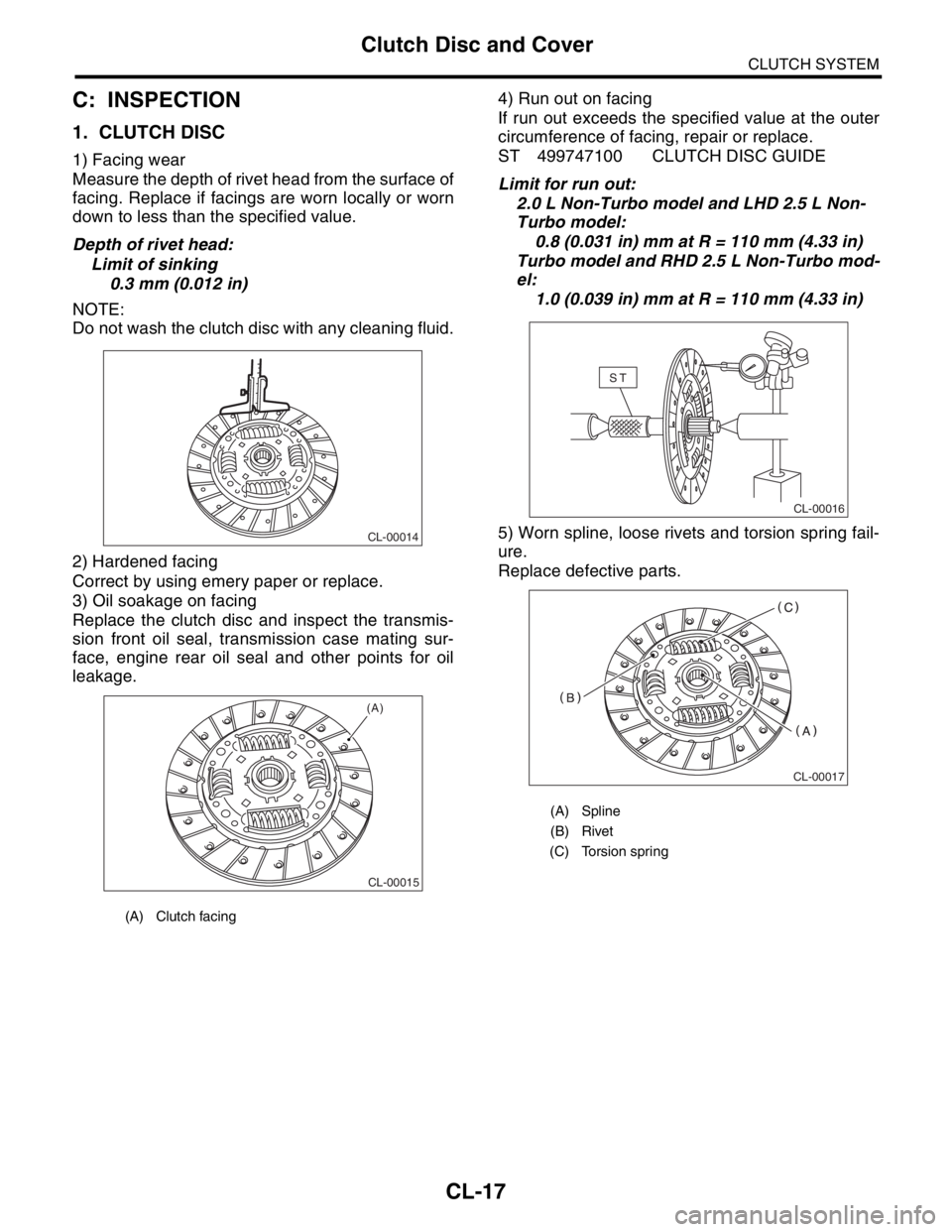
1) Facing wear
Measure the depth of rivet head from the surface of
facing. Replace if facings are worn locally or worn
down to less than the specified value.
Depth of rivet head:
Limit of sinking
0.3 mm (0.012 in)
NOTE:
Do not wash the clutch disc with any cleaning fluid.
2) Hardened facing
Correct by using emery paper or replace.
3) Oil soakage on facing
Replace the clutch disc and inspect the transmis-
sion front oil seal, transmission case mating sur-
face, engine rear oil seal and other points for oil
leakage.4) Run out on facing
If run out exceeds the specified value at the outer
circumference of facing, repair or replace.
ST 499747100 CLUTCH DISC GUIDE
Limit for run out:
2.0 L Non-Turbo model and LHD 2.5 L Non-
Turbo model:
0.8 (0.031 in) mm at R = 110 mm (4.33 in)
Turbo model and RHD 2.5 L Non-Turbo mod-
el:
1.0 (0.039 in) mm at R = 110 mm (4.33 in)
5) Worn spline, loose rivets and torsion spring fail-
ure.
Replace defective parts.
(A) Clutch facing
CL-00014
CL-00015
(A)
(A) Spline
(B) Rivet
(C) Torsion spring
CL-00016
ST
CL-00017
Page 2844 of 2870
CL-18
CLUTCH SYSTEM
Clutch Disc and Cover
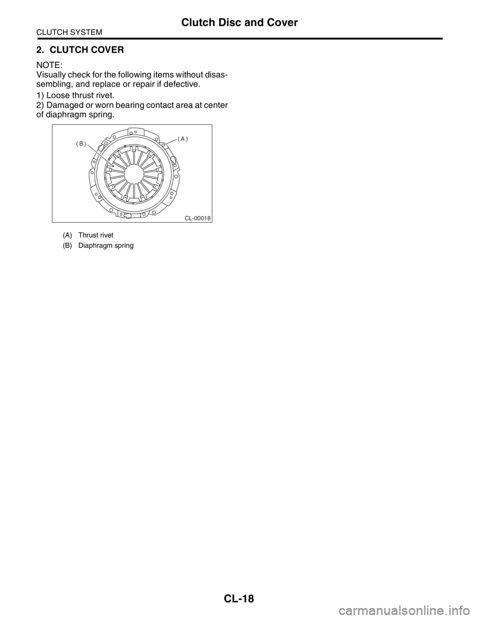
2. CLUTCH COVER
NOTE:
Visually check for the following items without disas-
sembling, and replace or repair if defective.
1) Loose thrust rivet.
2) Damaged or worn bearing contact area at center
of diaphragm spring.
(A) Thrust rivet
(B) Diaphragm spring
CL-00018
(A)
(B)
Page 2845 of 2870
CL-19
CLUTCH SYSTEM
Flywheel
3. Flywheel
A: REMOVAL
1) Remove the transmission assembly.
5MT-32, REMOVAL, Manual Transmission As-
sembly.>
2) Remove the clutch cover and clutch disc.
to CL-16, REMOVAL, Clutch Disc and Cover.>
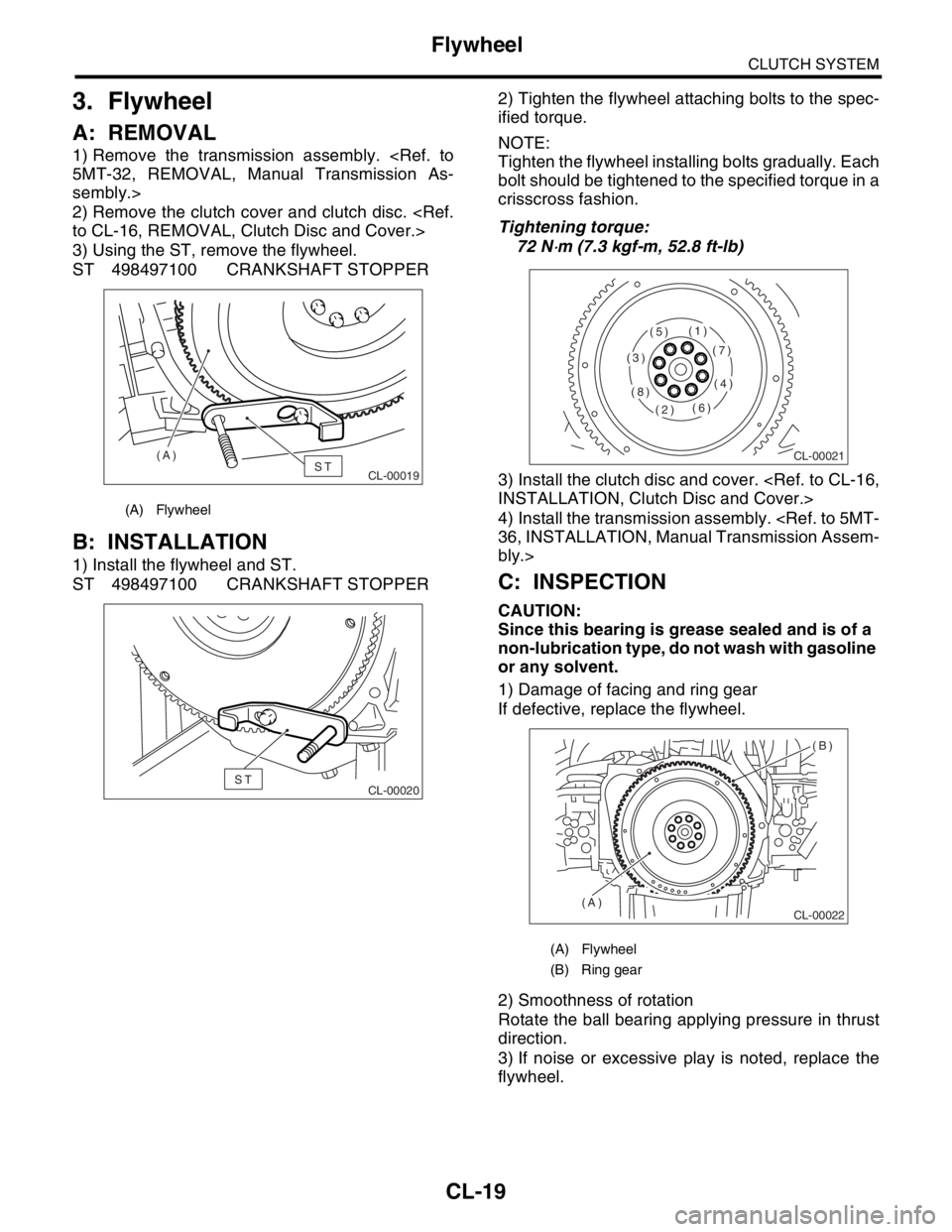
3) Using the ST, remove the flywheel.
ST 498497100 CRANKSHAFT STOPPER
B: INSTALLATION
1) Install the flywheel and ST.
ST 498497100 CRANKSHAFT STOPPER2) Tighten the flywheel attaching bolts to the spec-
ified torque.
NOTE:
Tighten the flywheel installing bolts gradually. Each
bolt should be tightened to the specified torque in a
crisscross fashion.
Tightening torque:
72 N
⋅m (7.3 kgf-m, 52.8 ft-lb)
3) Install the clutch disc and cover.
INSTALLATION, Clutch Disc and Cover.>
4) Install the transmission assembly.
36, INSTALLATION, Manual Transmission Assem-
bly.>
C: INSPECTION
CAUTION:
Since this bearing is grease sealed and is of a
non-lubrication type, do not wash with gasoline
or any solvent.
1) Damage of facing and ring gear
If defective, replace the flywheel.
2) Smoothness of rotation
Rotate the ball bearing applying pressure in thrust
direction.
3) If noise or excessive play is noted, replace the
flywheel.
(A) Flywheel
CL-00019ST (A)
CL-00020ST
(A) Flywheel
(B) Ring gear
CL-00021
(1)
(2)
(3)
(4)
(5)
(6)
(7)
(8)
CL-00022
(B)
(A)
Page 2846 of 2870
CL-20
CLUTCH SYSTEM
Release Bearing and Lever
4. Release Bearing and Lever
A: REMOVAL
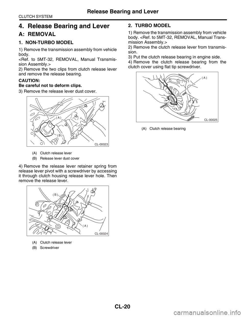
1. NON-TURBO MODEL
1) Remove the transmission assembly from vehicle
body.
sion Assembly.>
2) Remove the two clips from clutch release lever
and remove the release bearing.
CAUTION:
Be careful not to deform clips.
3) Remove the release lever dust cover.
4) Remove the release lever retainer spring from
release lever pivot with a screwdriver by accessing
it through clutch housing release lever hole. Then
remove the release lever.
2. TURBO MODEL
1) Remove the transmission assembly from vehicle
body.
mission Assembly.>
2) Remove the clutch release lever from transmis-
sion.
3) Put the clutch release bearing in engine side.
4) Remove the clutch release bearing from the
clutch cover using flat tip screwdriver.
(A) Clutch release lever
(B) Release lever dust cover
(A) Clutch release lever
(B) Screwdriver
CL-00023
(A)
(B)
CL-00024
(B)
(A)
(A) Clutch release bearing
CL-00025
(A)