Page 2822 of 2870
5MT-109
MANUAL TRANSMISSION AND DIFFERENTIAL
Counter Gear
25.Counter Gear
A: REMOVAL
1) Remove the manual transmission assembly
from vehicle.
Transmission Assembly.>
2) Remove the transfer case with extension case
assembly.
Case and Extension Case Assembly.>
3) Remove the transmission case.
62, REMOVAL, Transmission Case.>
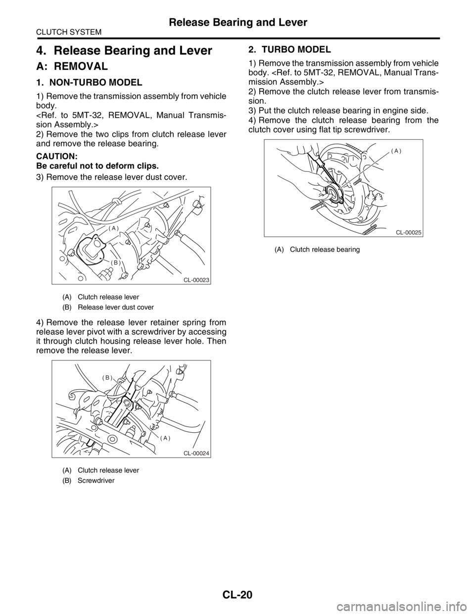
4) Move the counter gear shaft until it touches
transmission case, and remove the snap ring with a
suitable tool.
5) Slide the washer at rear of high-low counter
shaft, and remove the straight pin from counter
shaft.6) Remove the counter shaft from transmission
case, taking care not to drop the counter gear and
two washers.
NOTE:
Be careful not to damage the O-ring.
Be careful not to drop the straight pin on front
side.
Be careful not to drop the two needle bearings
and collar contained in counter gear.
B: INSTALLATION
1) Install the O-ring and straight pin onto counter
gear shaft.
2) Install the following parts in main case (Right-
side), and push the shaft perfectly into case.
Counter gear shaft
Two counter gear washers
Two needle bearings
Counter gear collar
Counter gear
Straight pin
Snap ring
3) Install the transmission case.
INSTALLATION, Transmission Case.>
4) Install the transfer case with extension case as-
sembly.
fer Case and Extension Case Assembly.>
5) Install the manual transmission assembly on ve-
hicle.
Transmission Assembly.>
NOTE:
Make sure that the cut-out end surface of counter
gear shaft does not protrude above the end surface
of the case.
Position the cut-out portion of counter gear shaft
as shown in the figure.(A) Snap ring
(A) Straight pin
(B) Counter gear
MT-00317
(A)
MT-00318(A)
(B)
(A) Counter shaft
(B) Counter gear
(C) Washers
MT-00319
(A)
(B)(C)
Page 2842 of 2870
CL-16
CLUTCH SYSTEM
Clutch Disc and Cover
2. Clutch Disc and Cover
A: REMOVAL
1) Remove the transmission assembly from vehicle
body.
mission Assembly.>
2) Install the ST on flywheel.
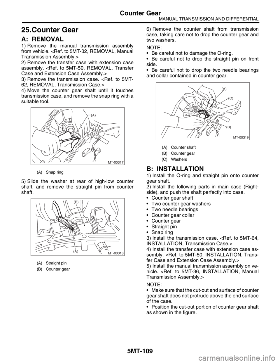
ST 499747100 CRANKSHAFT STOPPER
3) Remove the clutch cover and clutch disc.
NOTE:
Take care not to allow oil on the clutch disc fac-
ing.
Do not disassemble either the clutch cover or
clutch disc.
B: INSTALLATION
1) Insert the ST into clutch disc and install them on
the flywheel by inserting the ST end into pilot bear-
ing.
NOTE:
When installing the clutch disc, be careful to its di-
rection.
ST 499747100 CLUTCH DISC GUIDE2) Position “0” marks on clutch cover and flywheel
120° apart, and then tighten the clutch cover instal-
lation bolts diagonally.
NOTE:
“0” marks indicate the directions of residual un-
balance.
Temporarily tighten the bolts by hand. Each bolt
should be tightened to the specified torque in a
crisscross fashion.
Tightening torque:
16 N
⋅m (1.6 kgf-m, 11.6 ft-lb)
3) Remove the ST.
ST 499747100 CLUTCH DISC GUIDE
4) Install the transmission assembly.
36, INSTALLATION, Manual Transmission Assem-
bly.>
(A) Clutch cover
(A) Flywheel side
CL-00011
(A)
ST
CL-00012
(A)
ST
(A) “0” marks
CL-00013 (A)ST(2)
(5)
(3)(1)
(6)
(4)
Page 2845 of 2870
CL-19
CLUTCH SYSTEM
Flywheel
3. Flywheel
A: REMOVAL
1) Remove the transmission assembly.
5MT-32, REMOVAL, Manual Transmission As-
sembly.>
2) Remove the clutch cover and clutch disc.
to CL-16, REMOVAL, Clutch Disc and Cover.>
3) Using the ST, remove the flywheel.
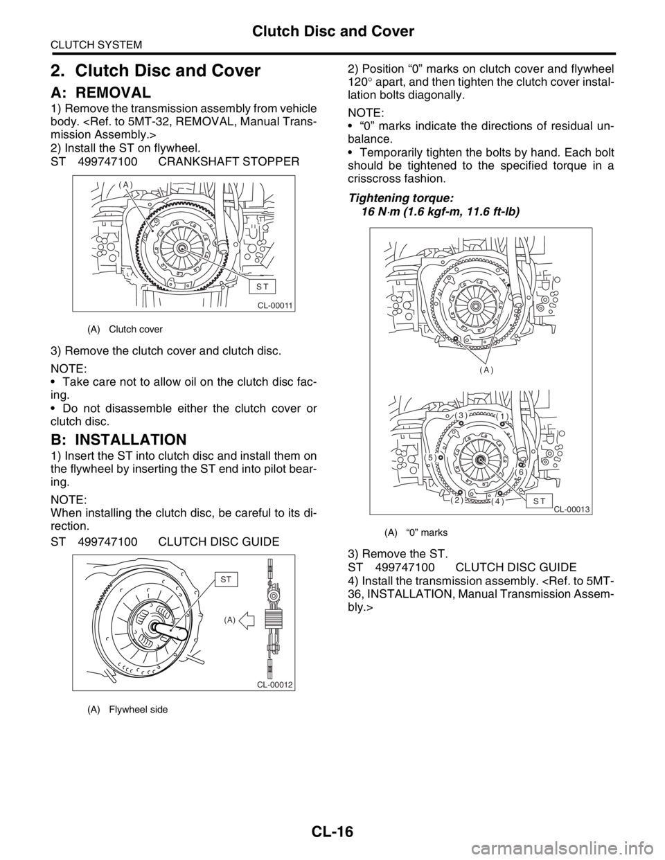
ST 498497100 CRANKSHAFT STOPPER
B: INSTALLATION
1) Install the flywheel and ST.
ST 498497100 CRANKSHAFT STOPPER2) Tighten the flywheel attaching bolts to the spec-
ified torque.
NOTE:
Tighten the flywheel installing bolts gradually. Each
bolt should be tightened to the specified torque in a
crisscross fashion.
Tightening torque:
72 N
⋅m (7.3 kgf-m, 52.8 ft-lb)
3) Install the clutch disc and cover.
INSTALLATION, Clutch Disc and Cover.>
4) Install the transmission assembly.
36, INSTALLATION, Manual Transmission Assem-
bly.>
C: INSPECTION
CAUTION:
Since this bearing is grease sealed and is of a
non-lubrication type, do not wash with gasoline
or any solvent.
1) Damage of facing and ring gear
If defective, replace the flywheel.
2) Smoothness of rotation
Rotate the ball bearing applying pressure in thrust
direction.
3) If noise or excessive play is noted, replace the
flywheel.
(A) Flywheel
CL-00019ST (A)
CL-00020ST
(A) Flywheel
(B) Ring gear
CL-00021
(1)
(2)
(3)
(4)
(5)
(6)
(7)
(8)
CL-00022
(B)
(A)
Page 2846 of 2870
CL-20
CLUTCH SYSTEM
Release Bearing and Lever
4. Release Bearing and Lever
A: REMOVAL
1. NON-TURBO MODEL
1) Remove the transmission assembly from vehicle
body.
sion Assembly.>
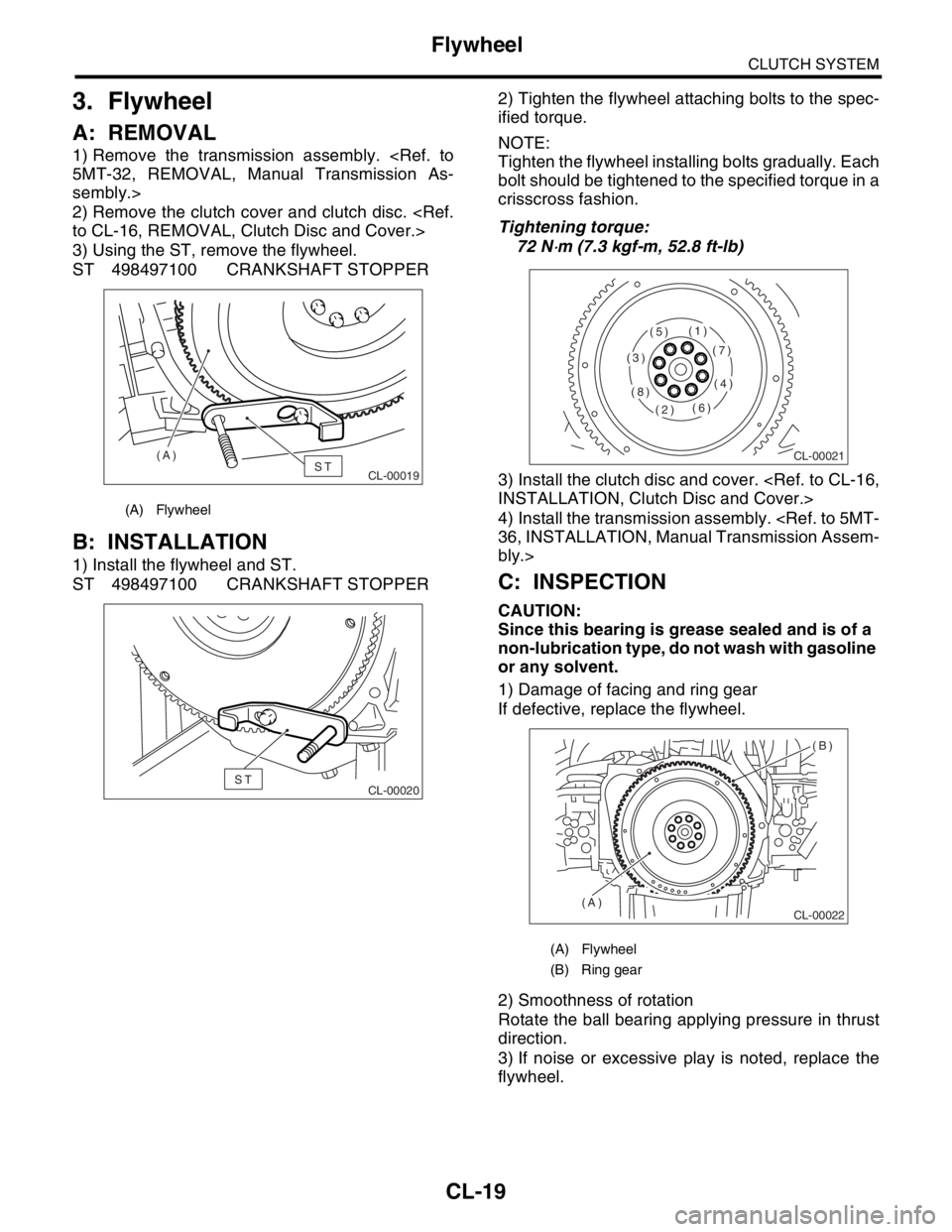
2) Remove the two clips from clutch release lever
and remove the release bearing.
CAUTION:
Be careful not to deform clips.
3) Remove the release lever dust cover.
4) Remove the release lever retainer spring from
release lever pivot with a screwdriver by accessing
it through clutch housing release lever hole. Then
remove the release lever.
2. TURBO MODEL
1) Remove the transmission assembly from vehicle
body.
mission Assembly.>
2) Remove the clutch release lever from transmis-
sion.
3) Put the clutch release bearing in engine side.
4) Remove the clutch release bearing from the
clutch cover using flat tip screwdriver.
(A) Clutch release lever
(B) Release lever dust cover
(A) Clutch release lever
(B) Screwdriver
CL-00023
(A)
(B)
CL-00024
(B)
(A)
(A) Clutch release bearing
CL-00025
(A)
Page:
< prev 1-8 9-16 17-24