Page 123 of 2870
AB-23
AIRBAG SYSTEM
Airbag Module Disposal (Deployment Processing On Vehicle)
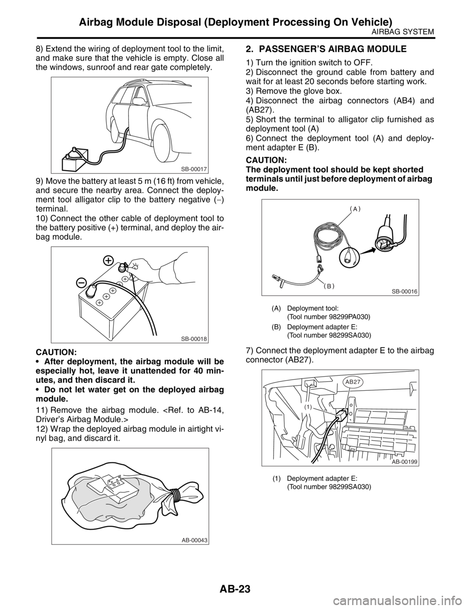
8) Extend the wiring of deployment tool to the limit,
and make sure that the vehicle is empty. Close all
the windows, sunroof and rear gate completely.
9) Move the battery at least 5 m (16 ft) from vehicle,
and secure the nearby area. Connect the deploy-
ment tool alligator clip to the battery negative (−)
terminal.
10) Connect the other cable of deployment tool to
the battery positive (+) terminal, and deploy the air-
bag module.
CAUTION:
After deployment, the airbag module will be
especially hot, leave it unattended for 40 min-
utes, and then discard it.
Do not let water get on the deployed airbag
module.
11) Remove the airbag module.
Driver’s Airbag Module.>
12) Wrap the deployed airbag module in airtight vi-
nyl bag, and discard it.2. PASSENGER’S AIRBAG MODULE
1) Turn the ignition switch to OFF.
2) Disconnect the ground cable from battery and
wait for at least 20 seconds before starting work.
3) Remove the glove box.
4) Disconnect the airbag connectors (AB4) and
(AB27).
5) Short the terminal to alligator clip furnished as
deployment tool (A)
6) Connect the deployment tool (A) and deploy-
ment adapter E (B).
CAUTION:
The deployment tool should be kept shorted
terminals until just before deployment of airbag
module.
7) Connect the deployment adapter E to the airbag
connector (AB27).
SB-00017
SB-00018
AB-00043
(A) Deployment tool:
(Tool number 98299PA030)
(B) Deployment adapter E:
(Tool number 98299SA030)
(1) Deployment adapter E:
(Tool number 98299SA030)
SB-00016
AB-00199
AB27
(1)
Page 124 of 2870
AB-24
AIRBAG SYSTEM
Airbag Module Disposal (Deployment Processing On Vehicle)
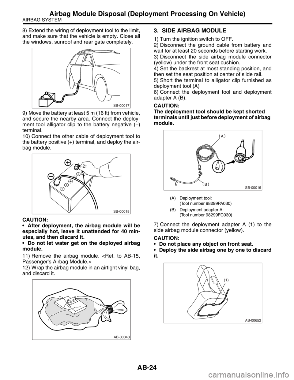
8) Extend the wiring of deployment tool to the limit,
and make sure that the vehicle is empty. Close all
the windows, sunroof and rear gate completely.
9) Move the battery at least 5 m (16 ft) from vehicle,
and secure the nearby area. Connect the deploy-
ment tool alligator clip to the battery negative (−)
terminal.
10) Connect the other cable of deployment tool to
the battery positive (+) terminal, and deploy the air-
bag module.
CAUTION:
After deployment, the airbag module will be
especially hot, leave it unattended for 40 min-
utes, and then discard it.
Do not let water get on the deployed airbag
module.
11) Remove the airbag module.
Passenger’s Airbag Module.>
12) Wrap the airbag module in an airtight vinyl bag,
and discard it.3. SIDE AIRBAG MODULE
1) Turn the ignition switch to OFF.
2) Disconnect the ground cable from battery and
wait for at least 20 seconds before starting work.
3) Disconnect the side airbag module connector
(yellow) under the front seat cushion.
4) Set the backrest at most standing position, and
then set the seat position at center of slide rail.
5) Short the terminal to alligator clip furnished as
deployment tool (A)
6) Connect the deployment tool and deployment
adapter A (B).
CAUTION:
The deployment tool should be kept shorted
terminals until just before deployment of airbag
module.
7) Connect the deployment adapter A (1) to the
side airbag module connector (yellow).
CAUTION:
Do not place any object on front seat.
Deploy the side airbag one by one to discard
it.
SB-00017
SB-00018
AB-00043
(A) Deployment tool:
(Tool number 98299PA030)
(B) Deployment adapter A:
(Tool number 98299FC030)
SB-00016
(1)
AB-00652
Page 125 of 2870
AB-25
AIRBAG SYSTEM
Airbag Module Disposal (Deployment Processing On Vehicle)
8) Extend the wiring of deployment tool to the limit,
and make sure that the vehicle is empty. Close all
the windows, sunroof and rear gate completely.
9) Move the battery at least 5 m (16 ft) from vehicle,
and secure the nearby area. Connect the deploy-
ment tool alligator clip to the battery negative (−)
terminal.
10) Connect the other cable of deployment tool to
the battery positive (+) terminal, and deploy the air-
bag module.
CAUTION:
After deployment, the airbag module will be
especially hot, leave it unattended for 40 min-
utes, and then discard it.
Do not let water get on the deployed airbag
module.
11) Remove the side airbag module.
16, REMOVAL, Side Airbag Module.>
12) Wrap the deployed airbag module in airtight vi-
nyl bag, and discard it.
SB-00017
SB-00018
AB-00043
Page 131 of 2870
FUJI HEAVY INDUSTRIES LTD. G8080GE7
2004 FORESTER SERVICE MANUAL QUICK REFERENCE INDEX
BODY SECTION
This service manual has been prepared
to provide SUBARU service personnel
with the necessary information and data
for the correct maintenance and repair
of SUBARU vehicles.
This manual includes the procedures
for maintenance, disassembling, reas-
sembling, inspection and adjustment of
components and diagnostics for guid-
ance of experienced mechanics.
Please peruse and utilize this manual
fully to ensure complete repair work for
satisfying our customers by keeping
their vehicle in optimum condition.
When replacement of parts during
repair work is needed, be sure to use
SUBARU genuine parts.
All information, illustration and specifi-
cations contained in this manual are
based on the latest product information
available at the time of publication
approval.HVAC SYSTEM
(HEATER, VENTILATOR AND A/C)AC
HVAC SYSTEM (AUTO A/C)
(DIAGNOSTIC)AC
AIRBAG SYSTEM AB
AIRBAG SYSTEM (DIAGNOSTIC) AB
SEAT BELT SYSTEM SB
LIGHTING SYSTEM LI
WIPER AND WASHER SYSTEM WW
ENTERTAINMENT ET
COMMUNICATION SYSTEM COM
GLASS/WINDOW/MIRROR GW
BODY STRUCTURE BS
INSTRUMENTATION/DRIVER INFO IDI
SEAT SE
SECURITY AND LOCK SL
SUNROOF/T-TOP/CONVERTIBLE TOP
(SUNROOF)SR
EXTERIOR/INTERIOR TRIM EI
EXTERIOR BODY PANEL EB
Page 233 of 2870
FUJI HEAVY INDUSTRIES LTD. G8080GE7
2004 FORESTER SERVICE MANUAL QUICK REFERENCE INDEX
BODY SECTION
This service manual has been prepared
to provide SUBARU service personnel
with the necessary information and data
for the correct maintenance and repair
of SUBARU vehicles.
This manual includes the procedures
for maintenance, disassembling, reas-
sembling, inspection and adjustment of
components and diagnostics for guid-
ance of experienced mechanics.
Please peruse and utilize this manual
fully to ensure complete repair work for
satisfying our customers by keeping
their vehicle in optimum condition.
When replacement of parts during
repair work is needed, be sure to use
SUBARU genuine parts.
All information, illustration and specifi-
cations contained in this manual are
based on the latest product information
available at the time of publication
approval.HVAC SYSTEM
(HEATER, VENTILATOR AND A/C)AC
HVAC SYSTEM (AUTO A/C)
(DIAGNOSTIC)AC
AIRBAG SYSTEM AB
AIRBAG SYSTEM (DIAGNOSTIC) AB
SEAT BELT SYSTEM SB
LIGHTING SYSTEM LI
WIPER AND WASHER SYSTEM WW
ENTERTAINMENT ET
COMMUNICATION SYSTEM COM
GLASS/WINDOW/MIRROR GW
BODY STRUCTURE BS
INSTRUMENTATION/DRIVER INFO IDI
SEAT SE
SECURITY AND LOCK SL
SUNROOF/T-TOP/CONVERTIBLE TOP
(SUNROOF)SR
EXTERIOR/INTERIOR TRIM EI
EXTERIOR BODY PANEL EB
Page 253 of 2870
FUJI HEAVY INDUSTRIES LTD. G8080GE7
2004 FORESTER SERVICE MANUAL QUICK REFERENCE INDEX
BODY SECTION
This service manual has been prepared
to provide SUBARU service personnel
with the necessary information and data
for the correct maintenance and repair
of SUBARU vehicles.
This manual includes the procedures
for maintenance, disassembling, reas-
sembling, inspection and adjustment of
components and diagnostics for guid-
ance of experienced mechanics.
Please peruse and utilize this manual
fully to ensure complete repair work for
satisfying our customers by keeping
their vehicle in optimum condition.
When replacement of parts during
repair work is needed, be sure to use
SUBARU genuine parts.
All information, illustration and specifi-
cations contained in this manual are
based on the latest product information
available at the time of publication
approval.HVAC SYSTEM
(HEATER, VENTILATOR AND A/C)AC
HVAC SYSTEM (AUTO A/C)
(DIAGNOSTIC)AC
AIRBAG SYSTEM AB
AIRBAG SYSTEM (DIAGNOSTIC) AB
SEAT BELT SYSTEM SB
LIGHTING SYSTEM LI
WIPER AND WASHER SYSTEM WW
ENTERTAINMENT ET
COMMUNICATION SYSTEM COM
GLASS/WINDOW/MIRROR GW
BODY STRUCTURE BS
INSTRUMENTATION/DRIVER INFO IDI
SEAT SE
SECURITY AND LOCK SL
SUNROOF/T-TOP/CONVERTIBLE TOP
(SUNROOF)SR
EXTERIOR/INTERIOR TRIM EI
EXTERIOR BODY PANEL EB
Page 287 of 2870
FUJI HEAVY INDUSTRIES LTD. G8080GE7
2004 FORESTER SERVICE MANUAL QUICK REFERENCE INDEX
BODY SECTION
This service manual has been prepared
to provide SUBARU service personnel
with the necessary information and data
for the correct maintenance and repair
of SUBARU vehicles.
This manual includes the procedures
for maintenance, disassembling, reas-
sembling, inspection and adjustment of
components and diagnostics for guid-
ance of experienced mechanics.
Please peruse and utilize this manual
fully to ensure complete repair work for
satisfying our customers by keeping
their vehicle in optimum condition.
When replacement of parts during
repair work is needed, be sure to use
SUBARU genuine parts.
All information, illustration and specifi-
cations contained in this manual are
based on the latest product information
available at the time of publication
approval.HVAC SYSTEM
(HEATER, VENTILATOR AND A/C)AC
HVAC SYSTEM (AUTO A/C)
(DIAGNOSTIC)AC
AIRBAG SYSTEM AB
AIRBAG SYSTEM (DIAGNOSTIC) AB
SEAT BELT SYSTEM SB
LIGHTING SYSTEM LI
WIPER AND WASHER SYSTEM WW
ENTERTAINMENT ET
COMMUNICATION SYSTEM COM
GLASS/WINDOW/MIRROR GW
BODY STRUCTURE BS
INSTRUMENTATION/DRIVER INFO IDI
SEAT SE
SECURITY AND LOCK SL
SUNROOF/T-TOP/CONVERTIBLE TOP
(SUNROOF)SR
EXTERIOR/INTERIOR TRIM EI
EXTERIOR BODY PANEL EB
Page 300 of 2870
WW-12
WIPER AND WASHER SYSTEM
Front Wiper Arm
6. Front Wiper Arm
A: REMOVAL
1) Open the hood.
2) Remove the cap.
3) Loosen the nut to remove arm.
B: INSTALLATION
1) Install in the reverse order of removal.
2) Operate the wiper once.
3) Align the wiper blade to ceramic print point mark
(A) of front window panel.
Tightening torque:
Refer to COMPONENT in General Descrip-
tion.
NENT, General Description.>
C: ADJUSTMENT
Operate the wiper once. Align the wiper blade to
ceramic print point mark (A) of front window panel.
WW-00047
WW-00048
(A)
WW-00048
(A)