Page 951 of 2870
ME(H4SO)-80
MECHANICAL
Cylinder Block
ST2 499057000 TORX PLUS
25) Install the housing cover.
26) Installation of oil pump
(1) Discard the front oil seal after removal. Re-
place with a new one using the ST.
ST 499587100 OIL SEAL INSTALLER
(2) Apply liquid gasket to the matching surface
of oil pump.
Liquid gasket:
THREE BOND 1215 (Part No. 004403007) or
equivalent(3) Apply a coat of engine oil to the inside of oil
seal.
(4) Install the oil pump on cylinder block. Be
careful not to damage the oil seal during instal-
lation.
Tightening torque:
6.4 N
⋅m (0.65 kgf-m, 4.7 ft-lb)
CAUTION:
Be sure to install the O-ring and seal when in-
stalling oil pump.
Align flat surface of oil pump’s inner rotor
with crankshaft before installation.
27) Install the water pump and gasket.
Tightening torque:
First; 12 N
⋅m (1.2 kgf-m, 8.7 ft-lb)
Second; 12 N
⋅m (1.2 kgf-m, 8.7 ft-lb)
CAUTION:
Be sure to use a new gasket.
When installing the water pump, tighten the
bolts in two stages in alphabetical sequence as
shown in the figure.
Model without ATF warmer
(A) Flywheel
(A) O-ring
(A)
ME-00382
ST1ST2
ME-00164
ME-00165
(A)
ME-00312
ME-00333
(B)
(F) (D)(C)
(A)
(E)
Page 967 of 2870

ME(H4SO)-96
MECHANICAL
Engine Noise
23.Engine Noise
A: INSPECTION
NOTE*:
When disconnecting fuel injector connector, the malfunction indicator light illuminates and DTC is stored in ECM memory.
Therefore, carry out the clear memory mode and inspection mode
after connecting fuel injector connector.Type of sound Condition Possible cause
Regular clicking soundSound increases as engine
speed increases. Valve mechanism is defective.
Incorrect valve clearance
Worn valve rocker
Worn camshaft
Broken valve spring
Heavy and dull clankOil pressure is low. Worn crankshaft main bearing
Worn connecting rod bearing (big end)
Oil pressure is normal. Loose flywheel mounting bolts
Damaged engine mounting
High-pitched clank (Spark
knock)Sound is noticeable when
accelerating with an overload. Ignition timing advanced
Accumulation of carbon inside combustion chamber
Wrong spark plug
Improper gasoline
Clank when engine speed is
medium (1,000 to 2,000 rpm).Sound is reduced when fuel
injector connector of noisy cyl-
inder is disconnected.
(NOTE*) Worn crankshaft main bearing
Worn bearing at crankshaft end of connecting rod
Knocking sound when engine
is operating under idling speed
and engine is warmSound is reduced when fuel
injector connector of noisy cyl-
inder is disconnected.
(NOTE*) Worn cylinder liner and piston ring
Broken or stuck piston ring
Worn piston pin and hole at piston end of connecting rod
Sound is not reduced if each
fuel injector connector is dis-
connected in turn. (NOTE*) Unusually worn valve lifter
Worn cam gear
Worn camshaft journal bore in crankcase
Squeaky sound — Insufficient generator lubrication
Rubbing sound — Defective generator brush and rotor contact
Gear scream when starting
engine— Defective ignition starter switch
Worn gear and starter pinion
Sound like polishing glass with
a dry cloth— Loose drive belt
Defective water pump shaft
Hissing sound — Loss of compression
Air leakage in air intake system, hoses, connections or mani-
folds
Timing belt noise — Loose timing belt
Belt contacting case/adjacent part
Valve tappet noise — Incorrect valve clearance
Page 984 of 2870

COOLING
CO(H4SO)
Page
1. General Description ....................................................................................2
2. Radiator Fan System ................................................................................13
3. Engine Coolant..........................................................................................19
4. Water Pump ..............................................................................................21
5. Thermostat ................................................................................................26
6. Radiator.....................................................................................................28
7. Radiator Cap .............................................................................................34
8. Radiator Main Fan and Fan Motor ............................................................35
9. Radiator Sub Fan and Fan Motor..............................................................40
10. Reservoir Tank ..........................................................................................41
11. Coolant Filler Tank ....................................................................................42
12. Engine Cooling System Trouble in General ..............................................43
Page 985 of 2870

CO(H4SO)-2
COOLING
General Description
1. General Description
A: SPECIFICATION
ModelNon-turbo Turbo
Cooling system Electric fan+Forced engine coolant circulation system
Total engine coolant capacity2(US qt, Imp qt)2.0L with ATF warmer:
Approx. 6.9 (7.29, 6.07)
2.0L AT:
Approx. 6.5 (6.87, 5.72)
2.0L MT:
Approx. 6.6 (6.98, 5.81)
2.5L AT:
Approx. 6.8 (7.19, 5.98)
2.5L MT:
Approx. 6.9 (7.29, 6.07)AT :
Approx. 7.3 (7.71, 6.42)
MT with oil cooler:
Approx. 7.3 (7.71, 6.42)
MT without oil cooler:
Approx. 7.4 (7.82, 6.51)
Water pumpType Centrifugal impeller type
Discharge perfor-
mance IDischarge 202 (5.3 US gal, 4.4 Imp gal)/min.
Pump speed — Discharge
pressure760 rpm — 2.9 kPa (0.3 mAq)
Engine coolant temperature 85°C (185°F)
Discharge perfor-
mance IIDischarge 1002 (26.4 US gal, 22.0 Imp gal)/min.
Pump speed — Discharge
pressure3,000 rpm — 49.0 kPa (5.0 mAq)
Engine coolant temperature 85°C (185°F)
Discharge perfor-
mance IIIDischarge 2002 (52.8 US gal, 44.0 Imp gal)/min.
Pump speed — Discharge
pressure6,000 rpm — 225.4 kPa (23.0 mAq)
Engine coolant temperature 85°C (185°F)
Impeller diameter 76 mm (2.99 in)
Number of impeller vanes 8
Pump pulley diameter 60 mm (2.36 in)
Clearance between
impeller and caseStandard 0.5 — 0.7 mm (0.020 — 0.028 in)
Limit 1.0 mm (0.039 in)
“Thrust” runout of impeller end 0.5 mm (0.020 in)
ThermostatType Wax pellet type
Starts to open 80 — 84°C (176 — 183°F) 76 — 80°C (169 — 176°F)
Fully opened 95°C (203°F) 91°C (196°F)
Valve lift 9.0 mm (0.354 in) or more
Valve bore 35 mm (1.38 in)
Radiator fanMotorMain fan 70 W2.0L AT (K4
★1) : 70 W
2.0L AT (EC, EK★1) :
120 W
2.0 L MT: 70 W
2.5 L: 120 W
Sub fan 70 W2.0L AT (K4
★1) : 70 W
2.0L AT (EC, EK★1) :
120 W
2.0 L MT: 70 W
2.5 L: 120 W
Fan diameter×Blade320 mm (11.81 in)×5 (main fan)
320 mm (11.81 in)×7 (sub fan)
Page 987 of 2870
CO(H4SO)-4
COOLING
General Description
B: COMPONENT
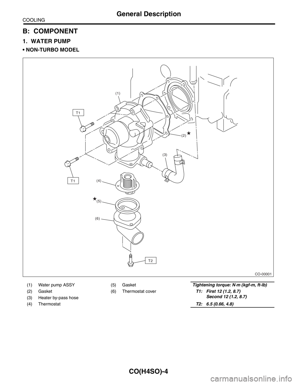
1. WATER PUMP
NON-TURBO MODEL
(1) Water pump ASSY (5) GasketTightening torque: N⋅m (kgf-m, ft-lb)
(2) Gasket (6) Thermostat coverT1: First 12 (1.2, 8.7)
Second 12 (1.2, 8.7)
(3) Heater by-pass hose
(4) ThermostatT2: 6.5 (0.66, 4.8)
CO-00001
T2(2) (1)
(4)
T1
(3)
(5)
(6)
T1
Page 988 of 2870
CO(H4SO)-5
COOLING
General Description
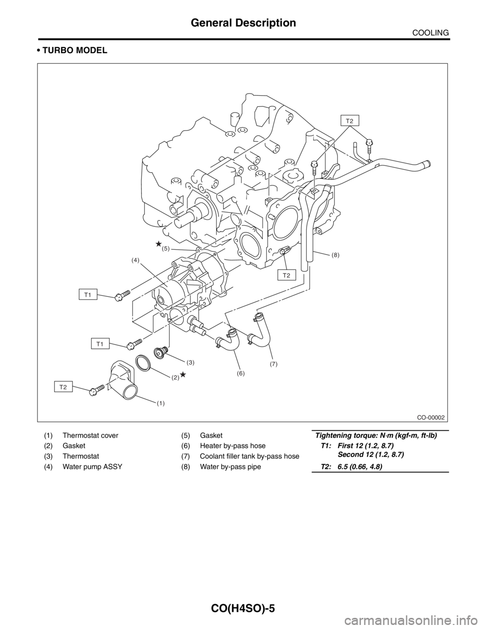
TURBO MODEL
(1) Thermostat cover (5) GasketTightening torque: N⋅m (kgf-m, ft-lb)
(2) Gasket (6) Heater by-pass hoseT1: First 12 (1.2, 8.7)
Second 12 (1.2, 8.7)
(3) Thermostat (7) Coolant filler tank by-pass hose
(4) Water pump ASSY (8) Water by-pass pipeT2: 6.5 (0.66, 4.8)
CO-00002
T2
(1)(3)
(6)(7)(8)
(4)
(2)
(5)
T2
T2
T1
T1
Page 989 of 2870
CO(H4SO)-6
COOLING
General Description
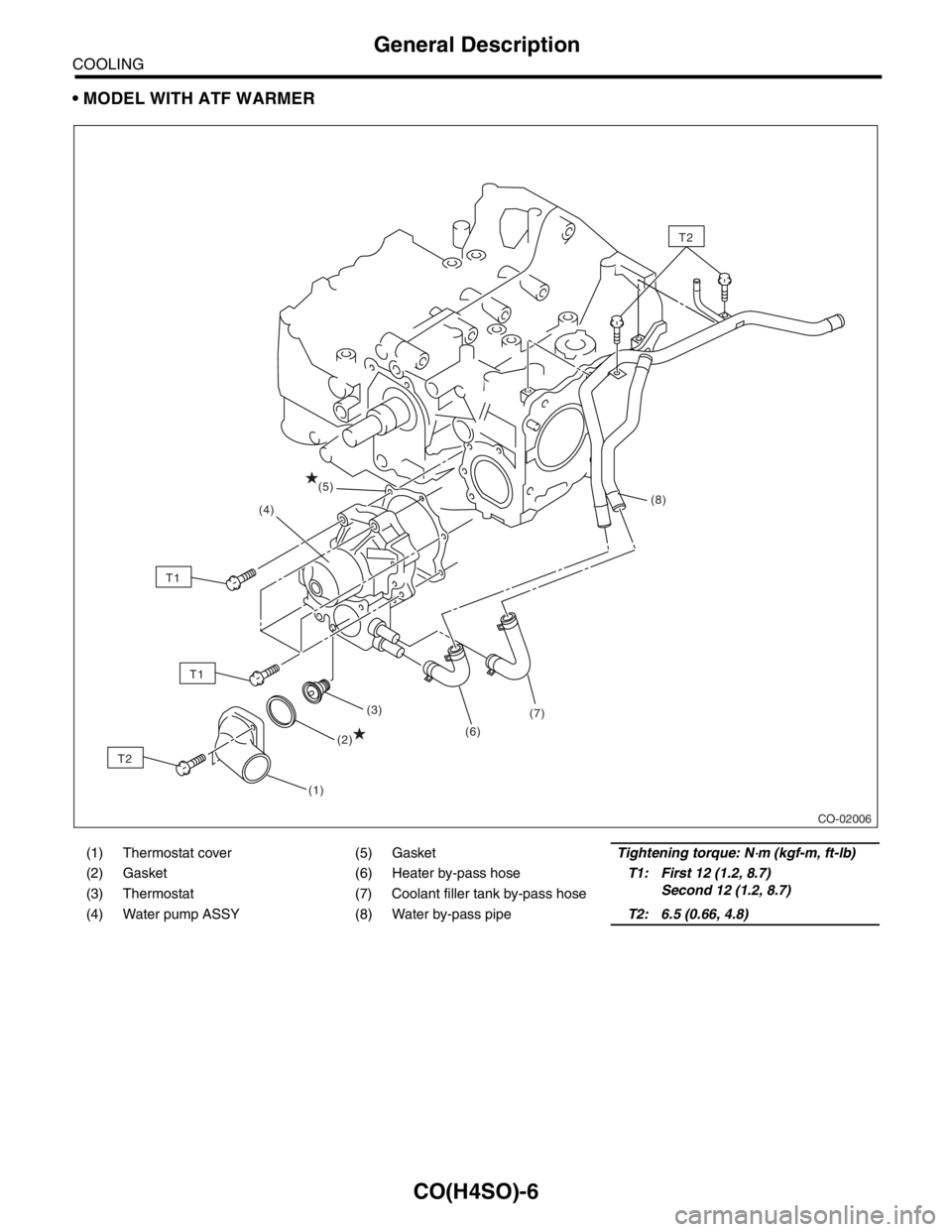
MODEL WITH ATF WARMER
(1) Thermostat cover (5) GasketTightening torque: N⋅m (kgf-m, ft-lb)
(2) Gasket (6) Heater by-pass hoseT1: First 12 (1.2, 8.7)
Second 12 (1.2, 8.7)
(3) Thermostat (7) Coolant filler tank by-pass hose
(4) Water pump ASSY (8) Water by-pass pipeT2: 6.5 (0.66, 4.8)
CO-02006
(1)(3)
(6)(7)(8)
(4)
(2)
(5)
T2
T2
T1
T1
Page 1004 of 2870
CO(H4SO)-21
COOLING
Water Pump
4. Water Pump
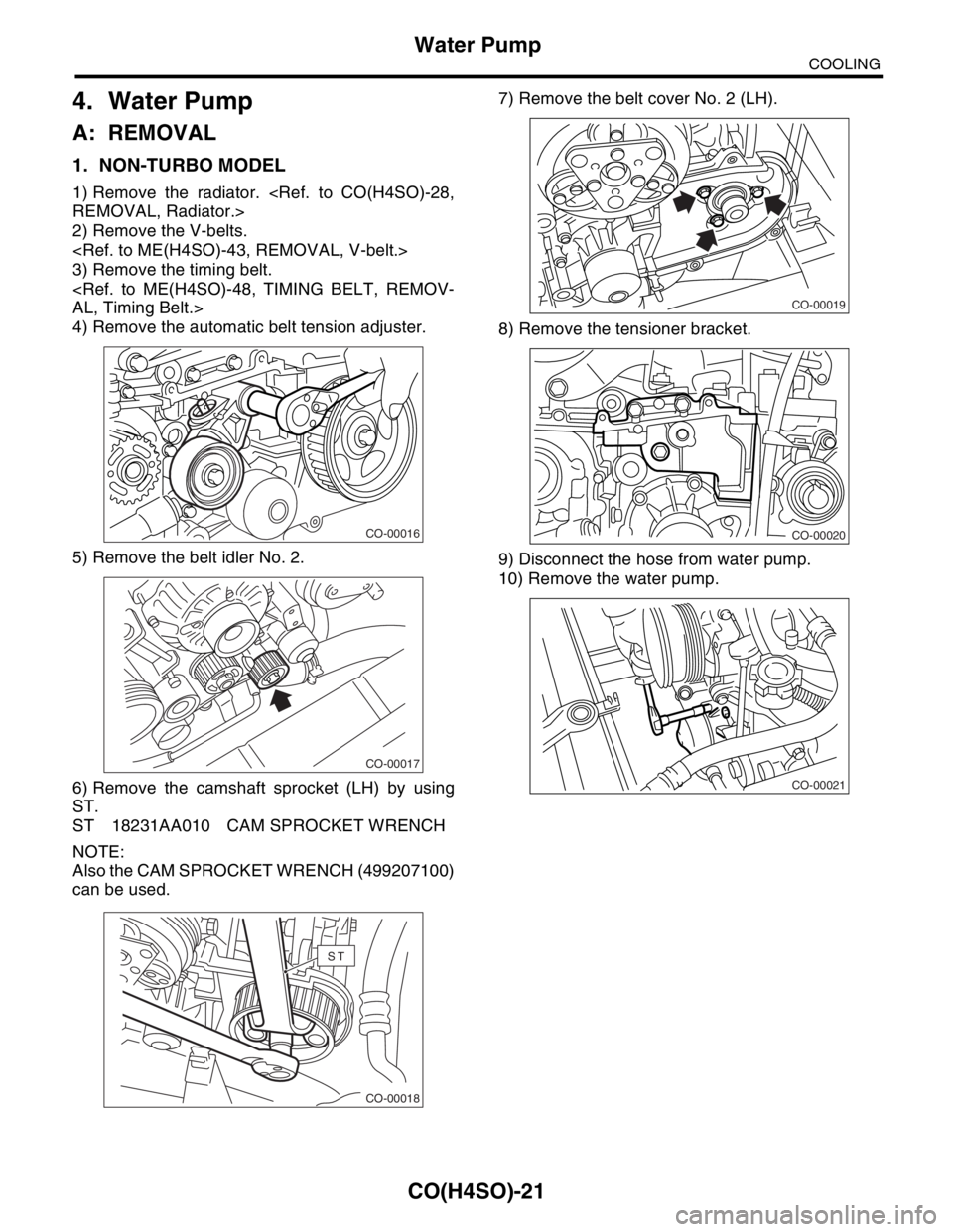
A: REMOVAL
1. NON-TURBO MODEL
1) Remove the radiator.
REMOVAL, Radiator.>
2) Remove the V-belts.
3) Remove the timing belt.
AL, Timing Belt.>
4) Remove the automatic belt tension adjuster.
5) Remove the belt idler No. 2.
6) Remove the camshaft sprocket (LH) by using
ST.
ST 18231AA010 CAM SPROCKET WRENCH
NOTE:
Also the CAM SPROCKET WRENCH (499207100)
can be used.7) Remove the belt cover No. 2 (LH).
8) Remove the tensioner bracket.
9) Disconnect the hose from water pump.
10) Remove the water pump.
CO-00016
CO-00017
CO-00018
ST
CO-00019
CO-00020
CO-00021