Page 454 of 2870
SL-34
SECURITY AND LOCK
Remote Openers
16.Remote Openers
A: REMOVAL
1. HOOD OPENER
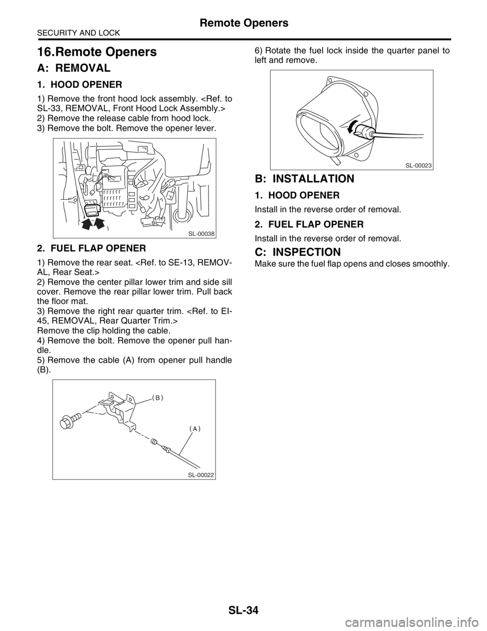
1) Remove the front hood lock assembly.
SL-33, REMOVAL, Front Hood Lock Assembly.>
2) Remove the release cable from hood lock.
3) Remove the bolt. Remove the opener lever.
2. FUEL FLAP OPENER
1) Remove the rear seat.
AL, Rear Seat.>
2) Remove the center pillar lower trim and side sill
cover. Remove the rear pillar lower trim. Pull back
the floor mat.
3) Remove the right rear quarter trim.
45, REMOVAL, Rear Quarter Trim.>
Remove the clip holding the cable.
4) Remove the bolt. Remove the opener pull han-
dle.
5) Remove the cable (A) from opener pull handle
(B).6) Rotate the fuel lock inside the quarter panel to
left and remove.
B: INSTALLATION
1. HOOD OPENER
Install in the reverse order of removal.
2. FUEL FLAP OPENER
Install in the reverse order of removal.
C: INSPECTION
Make sure the fuel flap opens and closes smoothly.
SL-00038
SL-00022
SL-00023
Page 494 of 2870
EI-18
EXTERIOR/INTERIOR TRIM
Front Grille
2. Front Grille
A: REMOVAL
1) Open the front hood.
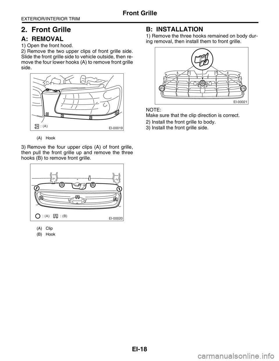
2) Remove the two upper clips of front grille side.
Slide the front grille side to vehicle outside, then re-
move the four lower hooks (A) to remove front grille
side.
3) Remove the four upper clips (A) of front grille,
then pull the front grille up and remove the three
hooks (B) to remove front grille.
B: INSTALLATION
1) Remove the three hooks remained on body dur-
ing removal, then install them to front grille.
NOTE:
Make sure that the clip direction is correct.
2) Install the front grille to body.
3) Install the front grille side.
(A) Hook
(A) Clip
(B) Hook
EI-00019: (A)
EI-00020: (A) : (B)EI-00021
Page 508 of 2870
EI-32
EXTERIOR/INTERIOR TRIM
Cowl Panel
8. Cowl Panel
A: REMOVAL
1) Open the front hood.
2) Remove the wiper arm.
MOVAL, Front Wiper Arm.>
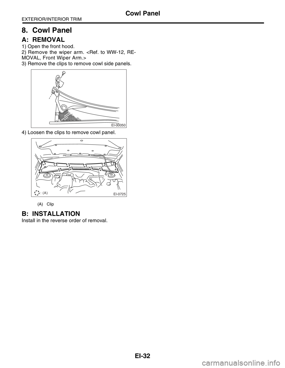
3) Remove the clips to remove cowl side panels.
4) Loosen the clips to remove cowl panel.
B: INSTALLATION
Install in the reverse order of removal.
(A) Clip
EI-00050
EI-0725: (A)
Page 539 of 2870
EB-9
EXTERIOR BODY PANEL
Front Hood Panel
2. Front Hood Panel
A: REMOVAL
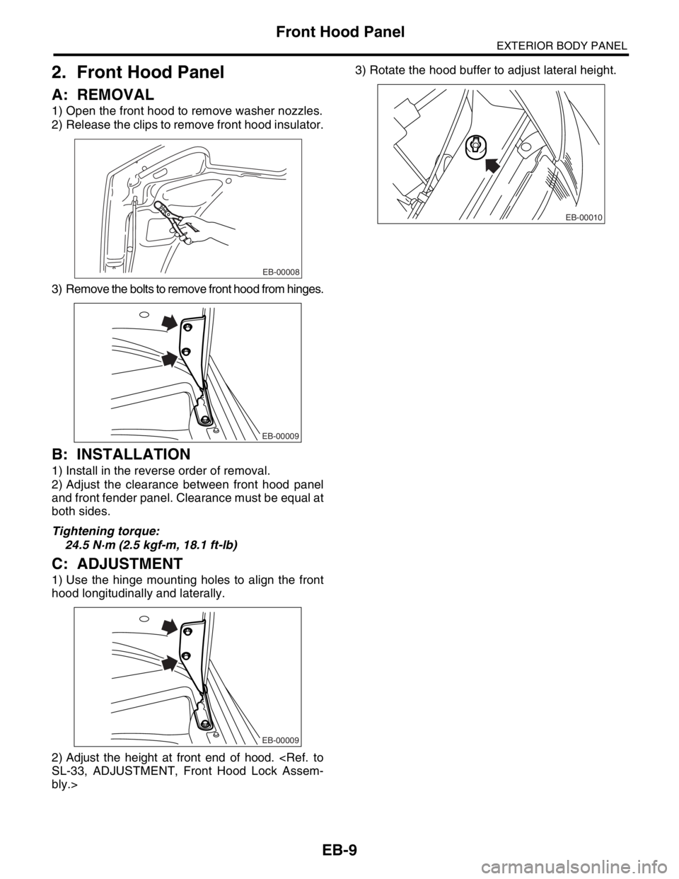
1) Open the front hood to remove washer nozzles.
2) Release the clips to remove front hood insulator.
3) Remove the bolts to remove front hood from hinges.
B: INSTALLATION
1) Install in the reverse order of removal.
2) Adjust the clearance between front hood panel
and front fender panel. Clearance must be equal at
both sides.
Tightening torque:
24.5 N·m (2.5 kgf-m, 18.1 ft-lb)
C: ADJUSTMENT
1) Use the hinge mounting holes to align the front
hood longitudinally and laterally.
2) Adjust the height at front end of hood.
SL-33, ADJUSTMENT, Front Hood Lock Assem-
bly.>3) Rotate the hood buffer to adjust lateral height.
EB-00008
EB-00009
EB-00009
EB-00010
Page 709 of 2870
NT-8
NOTE
Note
10.FRONT HOOD STAY INSTALLATION
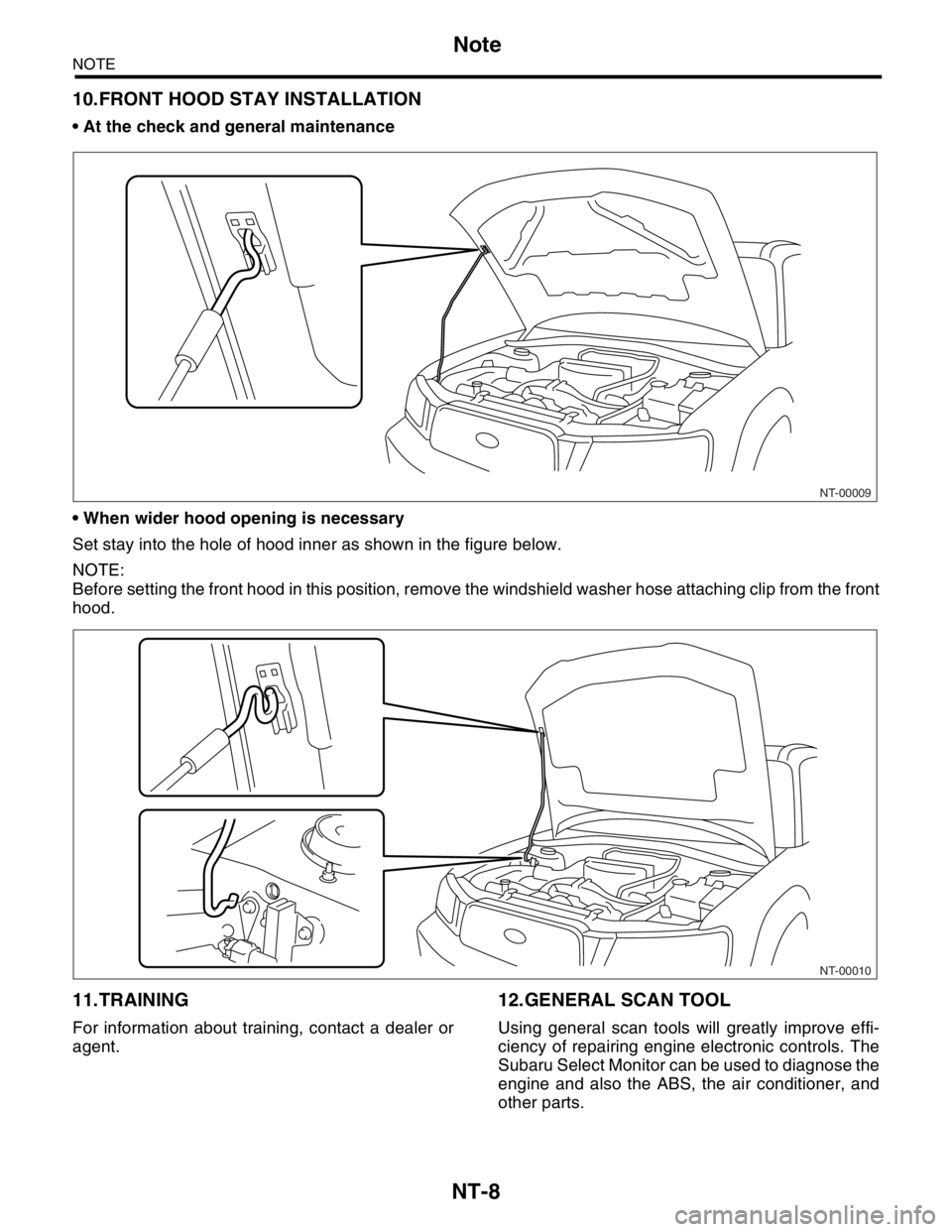
At the check and general maintenance
When wider hood opening is necessary
Set stay into the hole of hood inner as shown in the figure below.
NOTE:
Before setting the front hood in this position, remove the windshield washer hose attaching clip from the front
hood.
11.TRAINING
For information about training, contact a dealer or
agent.
12.GENERAL SCAN TOOL
Using general scan tools will greatly improve effi-
ciency of repairing engine electronic controls. The
Subaru Select Monitor can be used to diagnose the
engine and also the ABS, the air conditioner, and
other parts.
NT-00009
NT-00010
Page 726 of 2870

PI-3
PRE-DELIVERY INSPECTION
Pre-delivery Inspection
B: PDI PROCEDURE
Follow the procedures shown in the table below.
Static Checks Just After Vehicle Receipt
Step Check point
1. Appearance check (1) If the vehicle is covered with protective coating, visually check the vehicle
body for damage and dents. If the protective coating has been removed,
visually check the body paints for small areas of damage or stains.
(2) Visually check the glass and light lenses for any damage and cracks or
excessive gaps to the body sheet metal.
(3) Visually check the plated parts for any damage.
2. Tire check (1) Check the tires for damage, abnormal conditions, and dents on the
wheels.
(2) Check the tire air pressure.
3. Fuse installation If the vehicle is about to be delivered to the customer, attach a room light
fuse.
4. Connection of air conditioner harness If the vehicle is about to be delivered to the customer, connect the air condi-
tioner harness.
5. Check the doors for lock/unlock and open/close
operations.(1) Using the key, check if the door can be locked and unlocked normally.
(2) Open and close all doors to see that there are no abnormal conditions.
6. Operation check of double lock Check that the double lock operates normally.
7. Operation check of the child safety lock system. Check the child safety lock system operates normally.
8. Check the rear gate for lock/unlock and open/
close operations.(1) Check if the rear gate can be unlocked normally from the emergency
door.
(2) Open and close the rear gate to see that there are no abnormal condi-
tions.
(3) Operate the power door locking switch to check that the rear gate is
locked and unlocked normally.
9. Operation check of fuel lid opener lock release
leverOperate the fuel lid opener to check that the fuel lid is unlocked normally.
10. Accessory check Check that the following accessories are provided:
Owner’s manual
Warranty booklet
Service booklet
Spare key
Jack
Tool set
Spare tire
11. Operation check of hood lock release system Operate the hood lock release lever to check that the hood opens normally.
12. Battery Check the battery for any abnormal conditions such as rust and trace of bat-
tery fluid leaks.
13. Brake fluid Check the fluid amount.
14. Engine oil Check the oil amount.
15. Transmission fluid (1) Check the fluid amount.
(2) For AT, check the front differential oil.
16. AT front differential oil Check the AT front differential oil amount.
17. Coolant Check the coolant amount.
18. Clutch fluid Check the clutch fluid amount.
19. Window washer fluid Check the window washer fluid amount.
20. Hood latch check Check that the hood is closed and latched securely.
21. Keyless entry system Check that the keyless entry system operates normally.
22. Security system Check that the security system operates normally.
23. Seat (1) Check the seat surfaces for smears or dirt.
(2) Check the seat installation conditions and functionality.
24. Seat belt Check the seat belt installation conditions and functionality.
25. Wheel alignment Check that the wheel alignments are properly adjusted.
Page 731 of 2870
PI-8
PRE-DELIVERY INSPECTION
Pre-delivery Inspection
11.OPERATION CHECK OF HOOD LOCK
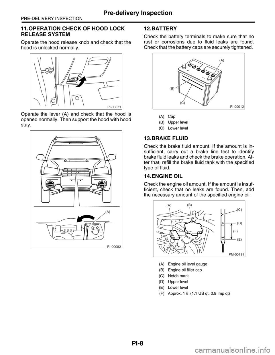
RELEASE SYSTEM
Operate the hood release knob and check that the
hood is unlocked normally.
Operate the lever (A) and check that the hood is
opened normally. Then support the hood with hood
stay.
12.BATTERY
Check the battery terminals to make sure that no
rust or corrosions due to fluid leaks are found.
Check that the battery caps are securely tightened.
13.BRAKE FLUID
Check the brake fluid amount. If the amount is in-
sufficient, carry out a brake line test to identify
brake fluid leaks and check the brake operation. Af-
ter that, refill the brake fluid tank with the specified
type of fluid.
14.ENGINE OIL
Check the engine oil amount. If the amount is insuf-
ficient, check that no leaks are found. Then, add
the necessary amount of the specified engine oil.
PI-00071
PI-00082
(A)
(A) Cap
(B) Upper level
(C) Lower level
(A) Engine oil level gauge
(B) Engine oil filler cap
(C) Notch mark
(D) Upper level
(E) Lower level
(F) Approx. 12 (1.1 US qt, 0.9 Imp qt)
PI-00012
(A)
(B)
(C)
PM-00181
(A)(B)
(D)
(E) (F)(C)
Page 903 of 2870
ME(H4SO)-34
MECHANICAL
Engine Assembly
9. Engine Assembly
A: REMOVAL
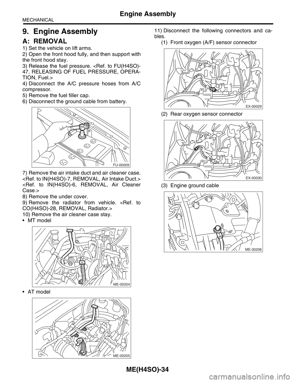
1) Set the vehicle on lift arms.
2) Open the front hood fully, and then support with
the front hood stay.
3) Release the fuel pressure.
47, RELEASING OF FUEL PRESSURE, OPERA-
TION, Fuel.>
4) Disconnect the A/C pressure hoses from A/C
compressor.
5) Remove the fuel filler cap.
6) Disconnect the ground cable from battery.
7) Remove the air intake duct and air cleaner case.
Case.>
8) Remove the under cover.
9) Remove the radiator from vehicle.
CO(H4SO)-28, REMOVAL, Radiator.>
10) Remove the air cleaner case stay.
MT model
AT model11) Disconnect the following connectors and ca-
bles.
(1) Front oxygen (A/F) sensor connector
(2) Rear oxygen sensor connector
(3) Engine ground cable
FU-00009
ME-00204
ME-00205
EX-00029
EX-00030
ME-00206