2004 SUBARU FORESTER Fuel injector
[x] Cancel search: Fuel injectorPage 819 of 2870
FU(H4SO)-37
FUEL INJECTION (FUEL SYSTEM)
Fuel Injector
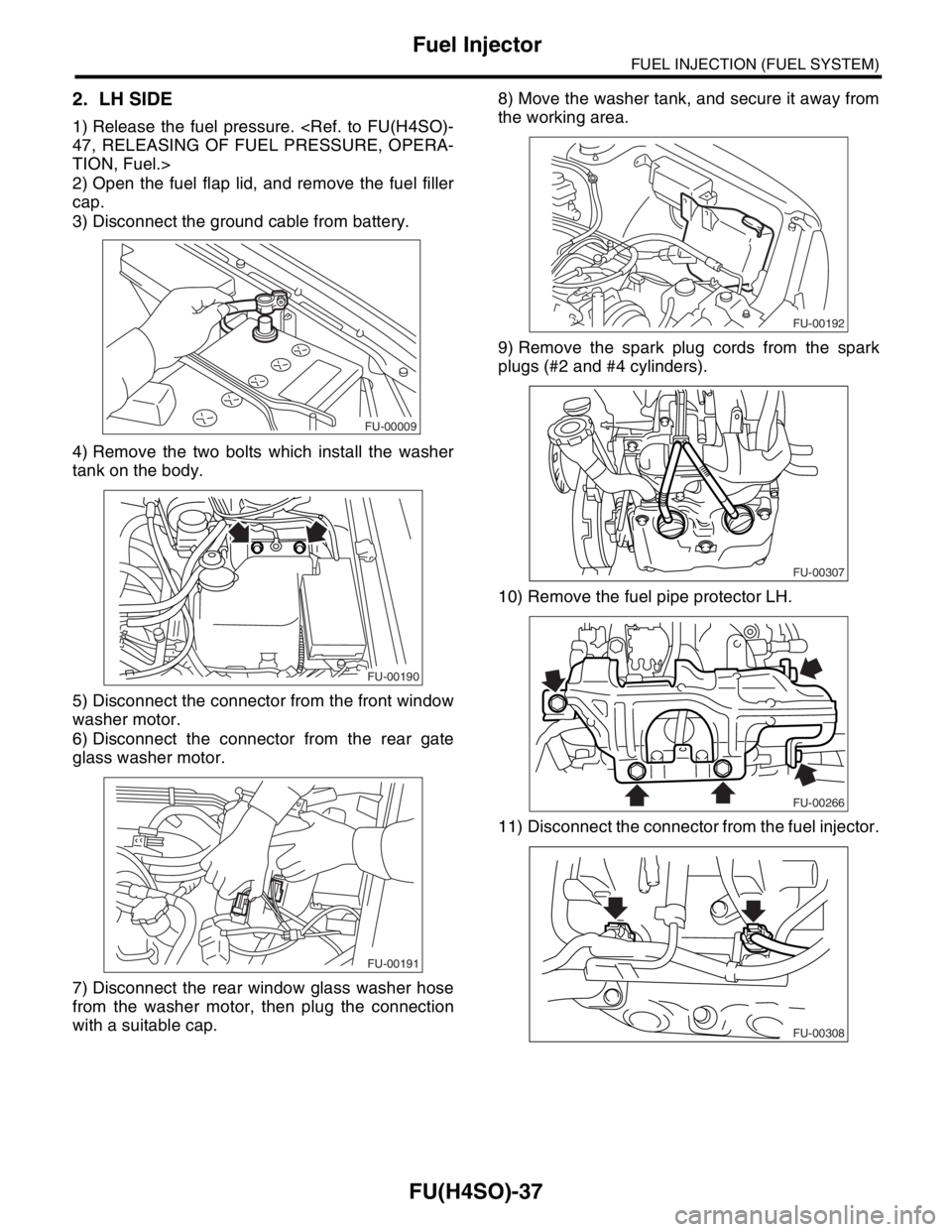
2. LH SIDE
1) Release the fuel pressure.
TION, Fuel.>
2) Open the fuel flap lid, and remove the fuel filler
cap.
3) Disconnect the ground cable from battery.
4) Remove the two bolts which install the washer
tank on the body.
5) Disconnect the connector from the front window
washer motor.
6) Disconnect the connector from the rear gate
glass washer motor.
7) Disconnect the rear window glass washer hose
from the washer motor, then plug the connection
with a suitable cap.8) Move the washer tank, and secure it away from
the working area.
9) Remove the spark plug cords from the spark
plugs (#2 and #4 cylinders).
10) Remove the fuel pipe protector LH.
11) Disconnect the connector from the fuel injector.
FU-00009
FU-00190
FU-00191
FU-00192
FU-00307
FU-00266
FU-00308
Page 820 of 2870
FU(H4SO)-38
FUEL INJECTION (FUEL SYSTEM)
Fuel Injector
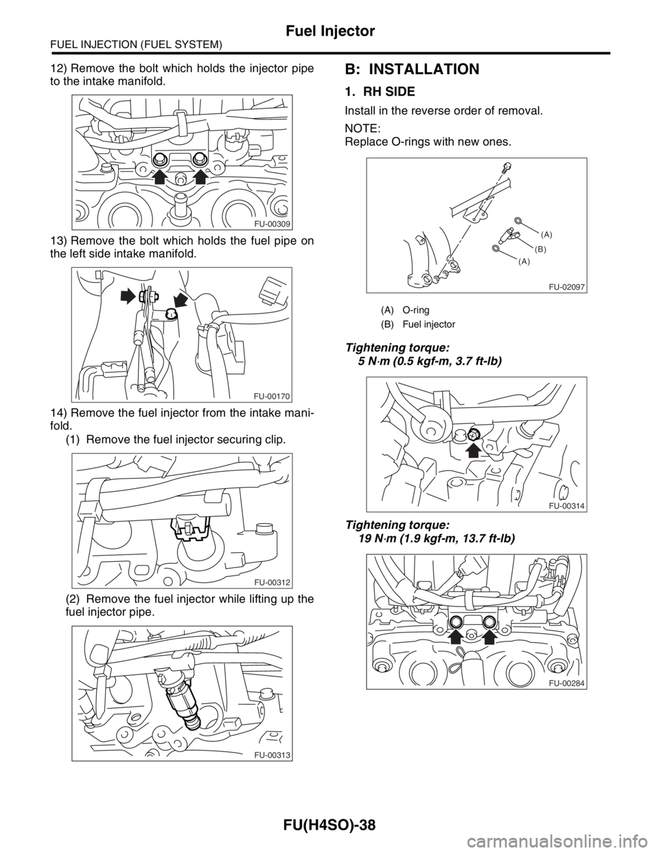
12) Remove the bolt which holds the injector pipe
to the intake manifold.
13) Remove the bolt which holds the fuel pipe on
the left side intake manifold.
14) Remove the fuel injector from the intake mani-
fold.
(1) Remove the fuel injector securing clip.
(2) Remove the fuel injector while lifting up the
fuel injector pipe.B: INSTALLATION
1. RH SIDE
Install in the reverse order of removal.
NOTE:
Replace O-rings with new ones.
Tightening torque:
5 N
⋅m (0.5 kgf-m, 3.7 ft-lb)
Tightening torque:
19 N
⋅m (1.9 kgf-m, 13.7 ft-lb)
FU-00309
FU-00170
FU-00312
FU-00313
(A) O-ring
(B) Fuel injector
FU-02097
(A)
(A)(B)
FU-00314
FU-00284
Page 821 of 2870
FU(H4SO)-39
FUEL INJECTION (FUEL SYSTEM)
Fuel Injector
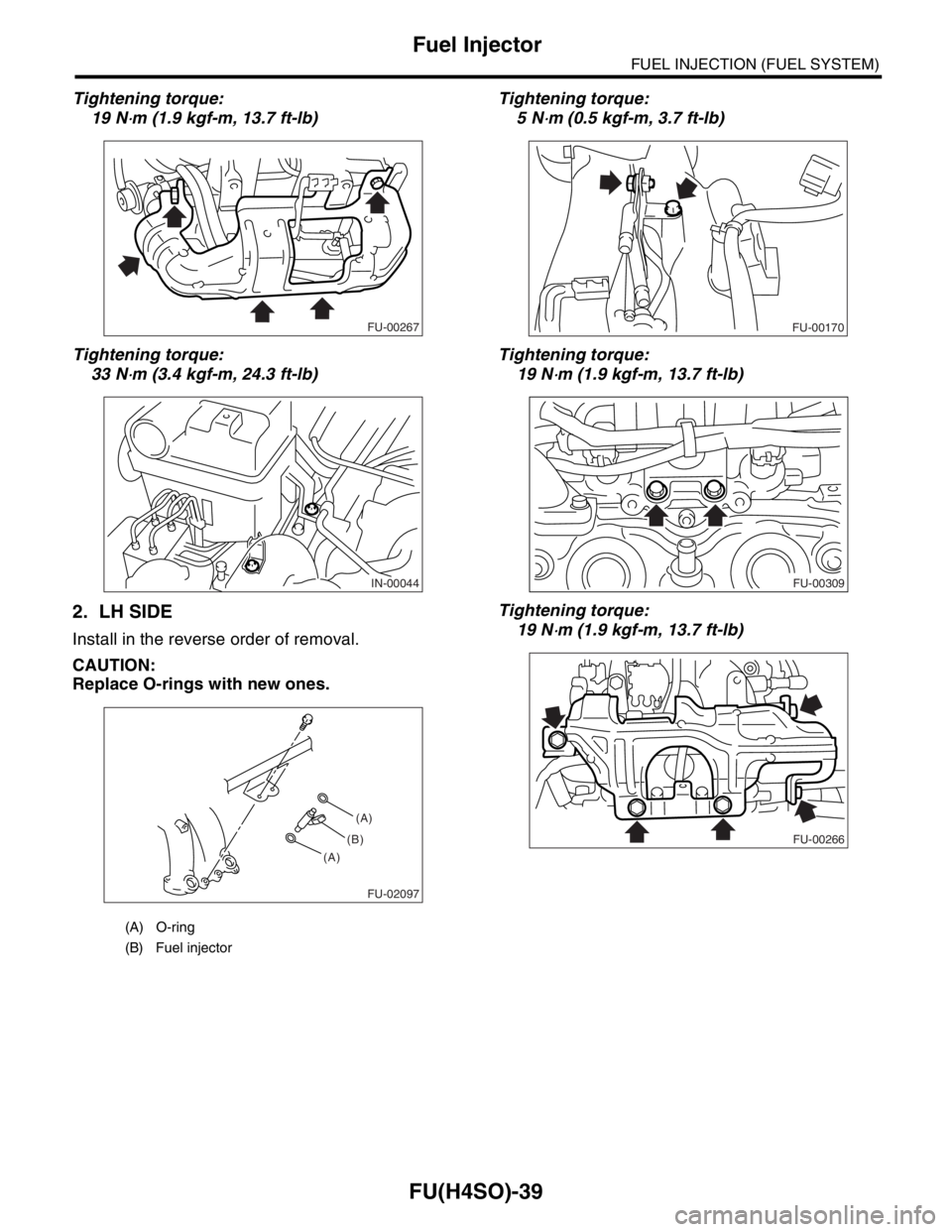
Tightening torque:
19 N
⋅m (1.9 kgf-m, 13.7 ft-lb)
Tightening torque:
33 N
⋅m (3.4 kgf-m, 24.3 ft-lb)
2. LH SIDE
Install in the reverse order of removal.
CAUTION:
Replace O-rings with new ones.Tightening torque:
5 N
⋅m (0.5 kgf-m, 3.7 ft-lb)
Tightening torque:
19 N
⋅m (1.9 kgf-m, 13.7 ft-lb)
Tightening torque:
19 N
⋅m (1.9 kgf-m, 13.7 ft-lb)
(A) O-ring
(B) Fuel injector
FU-00267
IN-00044
FU-02097
(A)
(A)(B)
FU-00170
FU-00309
FU-00266
Page 848 of 2870

FU(H4SO)-66
FUEL INJECTION (FUEL SYSTEM)
Fuel System Trouble in General
29.Fuel System Trouble in General
A: INSPECTION
NOTE:
When the vehicle is left unattended for an ex-
tended period of time, water may accumulate in the
fuel tank.
To prevent water condensation.
(1) Top off the fuel tank or drain the fuel com-
pletely.
(2) Drain the water condensation from the fuel
filter.
Refilling the fuel tank.
Refill the fuel tank while there is still some fuel left in
the tank.
Protecting the fuel system against freezing and
water condensation.
(3) Cold areas :
In snow-covered areas, mountainous areas, ski-
ing areas, etc. where ambient temperatures
drop below 0°C (32°F) throughout the winter
season, use an anti-freeze solution in the fuel
tank. Refueling will also complement the effect
of anti-freeze solution each time the fuel leveldrops to about one-half. After the winter season,
drain the water which may have accumulated in
the fuel filter and fuel tank in the manner same
as that described under “Affected areas” below.
(4) Affected areas :
When the water condensation is notched in the
fuel filter, drain the water from both the fuel filter
and fuel tank or use a water removing agent (or
anti-freeze solution) in the fuel tank.
Observe the instructions, notes, etc., indicated
on the label affixed to the anti-freeze solution (wa-
ter removing agent) container before use.
Trouble and possible cause Corrective action
1. Insufficient fuel supply to the injector
1) Fuel pump will not operate.
❍Defective terminal contact.Inspect connections, especially ground, and tighten
securely.
❍Trouble in electromagnetic or electronic circuit parts. Replace fuel pump.
2) Lowering of fuel pump function. Replace fuel pump.
3) Clogged dust or water in the fuel filter. Replace fuel filter, clean or replace fuel tank.
4) Clogged or bent fuel pipe or hose. Clean, correct or replace fuel pipe or hose.
5) Air is mixed in the fuel system. Inspect or retighten each connection part.
6) Clogged or bent breather tube or pipe. Clean, correct or replace air breather tube or pipe.
7) Damaged diaphragm of pressure regulator. Replace.
2. Leakage or blow out fuel
1) Loosened joints of the fuel pipe. Retightening.
2) Cracked fuel pipe, hose and fuel tank. Replace.
3) Defective welding part on the fuel tank. Replace.
4) Defective drain packing of the fuel tank. Replace.
5) Clogged or bent air breather tube or air vent tube.Clean, correct or replace air breather tube or air vent
tube.
3. Gasoline smell inside of compartment
1)Loose joints at air breather tube, air vent tube and fuel filler
pipe.Retightening.
2) Defective packing air tightness on the fuel saucer. Correct or replace packing.
3) Cracked fuel separator. Replace separator.
4) Inoperative fuel pump modulator or circuit. Replace.
4. Defective fuel meter indicator
1) Defective operation of fuel level sensor. Replace.
2) Defective operation of fuel meter. Replace.
5. Noise
1) Large operation noise or vibration of fuel pump. Replace.
Page 967 of 2870

ME(H4SO)-96
MECHANICAL
Engine Noise
23.Engine Noise
A: INSPECTION
NOTE*:
When disconnecting fuel injector connector, the malfunction indicator light illuminates and DTC is stored in ECM memory.
Therefore, carry out the clear memory mode
Regular clicking soundSound increases as engine
speed increases. Valve mechanism is defective.
Incorrect valve clearance
Worn valve rocker
Worn camshaft
Broken valve spring
Heavy and dull clankOil pressure is low. Worn crankshaft main bearing
Worn connecting rod bearing (big end)
Oil pressure is normal. Loose flywheel mounting bolts
Damaged engine mounting
High-pitched clank (Spark
knock)Sound is noticeable when
accelerating with an overload. Ignition timing advanced
Accumulation of carbon inside combustion chamber
Wrong spark plug
Improper gasoline
Clank when engine speed is
medium (1,000 to 2,000 rpm).Sound is reduced when fuel
injector connector of noisy cyl-
inder is disconnected.
(NOTE*) Worn crankshaft main bearing
Worn bearing at crankshaft end of connecting rod
Knocking sound when engine
is operating under idling speed
and engine is warmSound is reduced when fuel
injector connector of noisy cyl-
inder is disconnected.
(NOTE*) Worn cylinder liner and piston ring
Broken or stuck piston ring
Worn piston pin and hole at piston end of connecting rod
Sound is not reduced if each
fuel injector connector is dis-
connected in turn. (NOTE*) Unusually worn valve lifter
Worn cam gear
Worn camshaft journal bore in crankcase
Squeaky sound — Insufficient generator lubrication
Rubbing sound — Defective generator brush and rotor contact
Gear scream when starting
engine— Defective ignition starter switch
Worn gear and starter pinion
Sound like polishing glass with
a dry cloth— Loose drive belt
Defective water pump shaft
Hissing sound — Loss of compression
Air leakage in air intake system, hoses, connections or mani-
folds
Timing belt noise — Loose timing belt
Belt contacting case/adjacent part
Valve tappet noise — Incorrect valve clearance
Page 1104 of 2870
EN(H4SO)-6
ENGINE (DIAGNOSTIC)
General Description
3. General Description
A: CAUTION
1) Airbag system wiring harness is routed near the
ECM, main relay and fuel pump relay.
CAUTION:
All air bag system wiring harnesses and con-
nectors are yellow. Do not use the electrical
test equipment on these circuits.
Be careful not to damage the Airbag system
wiring harness when servicing the ECM, TCM,
main relay and fuel pump relay.
2) Never connect the battery in reverse polarity.
The ECM will be destroyed immediately.
The fuel injector and other part will be damaged.
3) Do not disconnect the battery terminals while the
engine is running.
A large counter electromotive force will be generat-
ed in the generator, and this voltage may damage
electronic parts such as ECM, etc.
4) Before disconnecting the connectors of each
sensor and the ECM, be sure to turn the ignition
switch to OFF.
5) Poor contact has been identified as a primary
cause of this problem. Measure the voltage or re-
sistance of individual sensor or all electrical control
modules using a tapered pin with a diameter of less
than 0.64 mm (0.025 in). Do not insert the pin more
than 5 mm (0.20 in) into the part.
6) Remove the ECM from the located position after
disconnecting two cables on battery.
Otherwise, the ECM may be damaged.
CAUTION:
When replacing the ECM, be careful not to use
the wrong spec. ECM to avoid any damage on
the fuel injection system.
7) Connectors to each sensor in the engine com-
partment and the harness connectors on the en-
gine side and body side are all designed to be
waterproof. However, it is still necessary to take
care not to allow water to get into the connectors
when washing the vehicle, or when servicing the
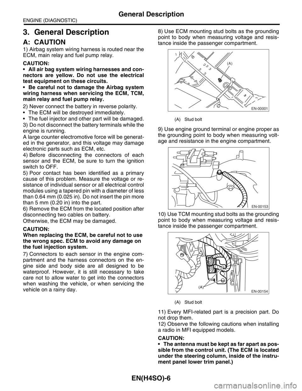
vehicle on a rainy day.8) Use ECM mounting stud bolts as the grounding
point to body when measuring voltage and resis-
tance inside the passenger compartment.
9) Use engine ground terminal or engine proper as
the grounding point to body when measuring volt-
age and resistance in the engine compartment.
10) Use TCM mounting stud bolts as the grounding
point to body when measuring voltage and resis-
tance inside the passenger compartment.
11) Every MFI-related part is a precision part. Do
not drop them.
12) Observe the following cautions when installing
a radio in MFI equipped models.
CAUTION:
The antenna must be kept as far apart as pos-
sible from the control unit. (The ECM is located
under the steering column, inside of the instru-
ment panel lower trim panel.)
(A) Stud bolt
(A) Stud bolt
EN-00001
(A)
EN-00153
EN-00154(A)
Page 1106 of 2870
EN(H4SO)-8
ENGINE (DIAGNOSTIC)
General Description
The OBD-II diagnostics procedure is different
from the usual diagnosis procedure. When trouble-
shooting the OBD-II models, connect Subaru Se-
lect Monitor or the OBD-II general scan tool to the
vehicle.
2. ENGINE AND EMISSION CONTROL SYS-
TEM
MFI system is a system that supplies the opti-
mum air-fuel mixture to the engine for all the vari-
ous operating conditions through the use of the
latest electronic technology.
With this system fuel, which is pressurized at a con-
stant pressure, is injected into the intake air pas-
sage of the cylinder head. The injection quantity of
fuel is controlled by an intermittent injection system
where the electro-magnetic injection valve (fuel in-
jector) opens only for a short period of time, de-
pending on the quantity of air required for one cycle
of operation. In actual operation, the injection quan-
tity is determined by the duration of an electric sig-
nal applied to the fuel injector and this permits
simple, yet highly precise metering of the fuel.
Further, all the operating conditions of the engine
are converted into electric signals, and this results
in additional features of the system, such as large
improved adaptability, easier addition of compen-
sating element, etc.The MFI system also has the following features:
Reduced emission of harmful exhaust gases.
Reduced in fuel consumption.
Increased engine output.
Superior acceleration and deceleration.
Excellent engine start and warm-up perfor-
mance by the correction of engine coolant tem-
perature and intake air temperature.3. AUTOMATIC TRANSMISSION AND
ELECTRONIC-HYDRAULIC CONTROL SYS-
TEM
The electronic-hydraulic control system consists of
various sensors and switches, TCM and the hy-
draulic controller including solenoid valves. The
system controls the transmission body including
shift control, lock-up control, overrunning clutch
control, line pressure control and shift timing con-
trol. It also controls the AWD transfer clutch. In oth-
er words, the system detects various operating
conditions from various input signals and sends
output signals to shift solenoids 1, 2 and low clutch
timing solenoid and 2-4 brake timing solenoid, line
pressure duty solenoid, lock-up duty solenoid,
transfer duty solenoid and 2-4 brake duty solenoid
(a total of eight solenoids).
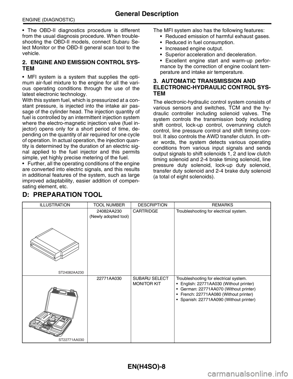
D: PREPARATION TOOL
ILLUSTRATION TOOL NUMBER DESCRIPTION REMARKS
24082AA230
(Newly adopted tool)CARTRIDGE Troubleshooting for electrical system.
22771AA030 SUBARU SELECT
MONITOR KITTroubleshooting for electrical system.
English: 22771AA030 (Without printer)
German: 22771AA070 (Without printer)
French: 22771AA080 (Without printer)
Spanish: 22771AA090 (Without printer)
ST24082AA230
ST22771AA030
Page 1155 of 2870

EN(H4SO)-57
ENGINE (DIAGNOSTIC)
Diagnostics for Engine Starting Failure
17.Diagnostics for Engine Starting Failure
A: PROCEDURE
1. Check for fuel amount.
↓
2. Inspection of starter motor circuit.
↓
3. Inspection of ECM power supply and ground line.
↓
4. Inspection of ignition control system.
↓
5. Inspection of fuel pump circuit.
↓
6. Inspection of fuel injector circuit.