Page 693 of 2870

SPC-4
SPECIFICATION
Forester
F: SUSPENSION
G: BRAKE
★: RHD model
H: TIRE
I: CAPACITY
★1: With oil pump★2: MT model with oil cooler Included★3: Model with ATF warmer Front Macpherson strut type, Independent, Coil spring
Rear Dual-link type, Independent, Coil spring
Model 2.0 L Non-turbo, 2.5 L Non-turbo
2.0 L Turbo, 2.5 L Non-turbo
★, 2.5 L Non-turbo
Service brake system Dual circuit hydraulic with vacuum suspended power unit
Front Ventilated disc brake
Rear Drum brake Disc brake
Parking brake Mechanical on rear brakes
Rim size 15×6J 16×6 1/2J
Tire size 205/70 R15 95H 215/60 R16 95V, P215/60 R16 94H
Type Steel belted radial, Tubeless
Model 2.0 L Non-turbo 2.0 L Turbo 2.5 L Non-turbo 2.5 L Turbo
Tr a n s m i s s i o n 5 M T 4 AT 5 M T 4 AT 5 M T 4 AT 5 M T 4 AT
Fuel tank2 (US gal, Imp gal) 60 (15.9, 13.2)
Engine oil
(When
replacing)2 (US qt, Imp qt) Approx. 4.0 (4.2, 3.5)
Tr a n s m i s -
sion gear oil2 (US qt, Imp qt)4.0
(4.2, 3.5)—3.5
(3.7, 3.1),
3.9
(4.1, 3.4)
★1
—4.0
(4.2, 3.5)—3.5
(3.7, 3.1)—
AT F2 (US qt, Imp qt) —8.4
(8.9, 7.4)—9.3
(9.8, 8.2)—9.3
(9.8, 8.2)—9.3
(9.8, 8.2)
Front differ-
ential gear
oil2 (US qt, Imp qt) —1.2
(1.3, 1.1)—1.2
(1.3, 1.1)—1.2
(1.3, 1.1)—1.2
(1.3, 1.1)
Rear differ-
ential gear
oil2 (US qt, Imp qt) 0.8 (0.8, 0.6)
Pow er
steering
fluid2 (US qt, Imp qt) 0.7 (0.7, 0.6)
Engine
coolant2 (US qt, Imp qt)6.6
(7.0, 5.8)6.5
(6.9, 5.7),
6.9
(7.3, 6.1)
★3
7.4
(7.8, 6.5)7.3
(7.7, 6.4)
★2
6.9
(7.3, 6.1)6.8
(7.2, 6.0)7.4
(7.8, 6.5)7.3
(7.7, 6.4)
Page 748 of 2870

PM-11
PERIODIC MAINTENANCE SERVICE
V-belt
6. V-belt
A: INSPECTION
1) Replace the belts, if cracks, fraying or wear is
found.
2) Check the V-belt tension and adjust it if neces-
sary by changing the generator installing position
or idler pulley installing position.
REPLACEMENT, V-belt.>
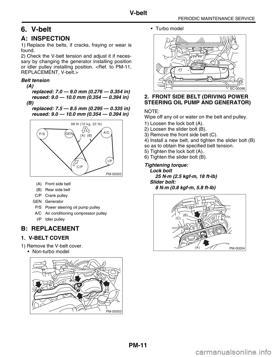
Belt tension
(A)
replaced: 7.0 — 9.0 mm (0.276 — 0.354 in)
reused: 9.0 — 10.0 mm (0.354 — 0.394 in)
(B)
replaced: 7.5 — 8.5 mm (0.295 — 0.335 in)
reused: 9.0 — 10.0 mm (0.354 — 0.394 in)
B: REPLACEMENT
1. V-BELT COVER
1) Remove the V-belt cover.
Non-turbo model Turbo model
2. FRONT SIDE BELT (DRIVING POWER
STEERING OIL PUMP AND GENERATOR)
NOTE:
Wipe off any oil or water on the belt and pulley.
1) Loosen the lock bolt (A).
2) Loosen the slider bolt (B).
3) Remove the front side belt (C).
4) Install a new belt, and tighten the slider bolt (B)
so as to obtain the specified belt tension.
5) Tighten the lock bolt (A).
6) Tighten the slider bolt (B).
Tightening torque:
Lock bolt
25 N·m (2.5 kgf-m, 18 ft-lb)
Slider bolt:
8 N·m (0.8 kgf-m, 5.8 ft-lb)
(A) Front side belt
(B) Rear side belt
C/P Crank pulley
GEN Generator
P/S Power steering oil pump pulley
A/C Air conditioning compressor pulley
I/P Idler pulley
C/P P/SA/C
GEN
(A)(B) 98 N (10 kg, 22 lb)
I/P
PM-00002
PM-00003
SC-00096
PM-00004
(B)
(C)
(A)
Page 779 of 2870

PM-42
PERIODIC MAINTENANCE SERVICE
Steering System (Power Steering)
(2) Retighten the adjusting screw to 7.4 N·m
(0.75 kgf-m, 5.4 ft-lb) and back off 25°.
(3) Apply Liquid gasket to at least 1/3 of entire
perimeter of adjusting screw thread.
(4) Install the lock nut. While holding the adjust-
ing screw with a wrench, tighten the lock nut us-
ing ST.
ST 926230000 SPANNER
Tightening torque (Lock nut):
39 N·m (4.0 kgf-m, 29 ft-lb)
Hold the adjusting screw with a wrench to pre-
vent it from turning it, while tightening the lock
nut.
4. TIE-ROD
1) Check the tie-rod and tie-rod ends for bends,
scratches or other damage.
2) Check the connections of knuckle ball joints for
play, inspect for damage on dust seals, and check
free play of ball studs. If the castle nut is loose, re-
tighten it to the specified torque, then tighten further
up to 60° until the cotter pin hole is aligned.
Tightening torque:
27 N·m (2.75 kgf-m, 19.9 ft-lb)3) Check the lock nut on tie-rod end for tightness. If
it is loose, retighten it to the specified torque.
Tightening torque:
83 N·m (8.5 kgf-m, 61.5 ft-lb)
5. POWER STEERING FLUID LEVEL
NOTE:
Check at power steering fluid temperature 20°C
(68°F); read the fluid level on the “COLD” side.
Check at power steering fluid temperature 80°C
(176°F); read the fluid level on the “HOT” side.
1) Place the vehicle with engine stopped on a flat
and level surface.
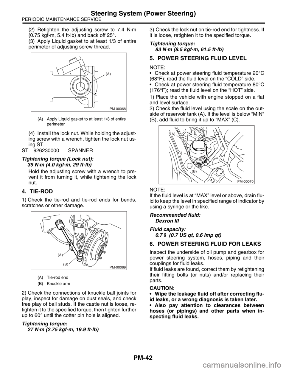
2) Check the fluid level using the scale on the out-
side of reservoir tank (A). If the level is below “MIN”
(B), add fluid to bring it up to “MAX” (C).
NOTE:
If the fluid level is at “MAX” level or above, drain flu-
id to keep the level in specified range of indicator by
using a syringe or the like.
Recommended fluid:
Dexron III
Fluid capacity:
0.72 (0.7 US qt, 0.6 Imp qt)
6. POWER STEERING FLUID FOR LEAKS
Inspect the underside of oil pump and gearbox for
power steering system, hoses, piping and their
couplings for fluid leaks.
If fluid leaks are found, correct them by retightening
their fitting bolts (or nuts) and/or replacing their
parts.
CAUTION:
Wipe the leakage fluid off after correcting flu-
id leaks, or a wrong diagnosis is taken later.
Also pay attention to clearances between
hoses (or pipings) and other parts when in-
specting fluid leaks.
(A) Apply Liquid gasket to at least 1/3 of entire
perimeter
(A) Tie-rod end
(B) Knuckle arm
PM-00068
(A)
PM-00069
(A)
(B)
PM-00070
(A)
(C)
(B)
Page 780 of 2870

PM-43
PERIODIC MAINTENANCE SERVICE
Steering System (Power Steering)
7. HOSES OF OIL PUMP FOR DAMAGES
Check the pressure hose and return hose of oil
pump for crack, swell or damage. Replace the hose
with a new one if necessary.
CAUTION:
Prevent the hoses from revolving and/or turn-
ing when installing hoses.
8. POWER STEERING PIPES FOR DAM-
AGE
Check the power steering pipes for corrosion and
damage.
Replace the pipes with a new one if necessary.
9. GEARBOX BOOTS
Inspect both sides of gearbox boots as follows, and
correct the defects if necessary.
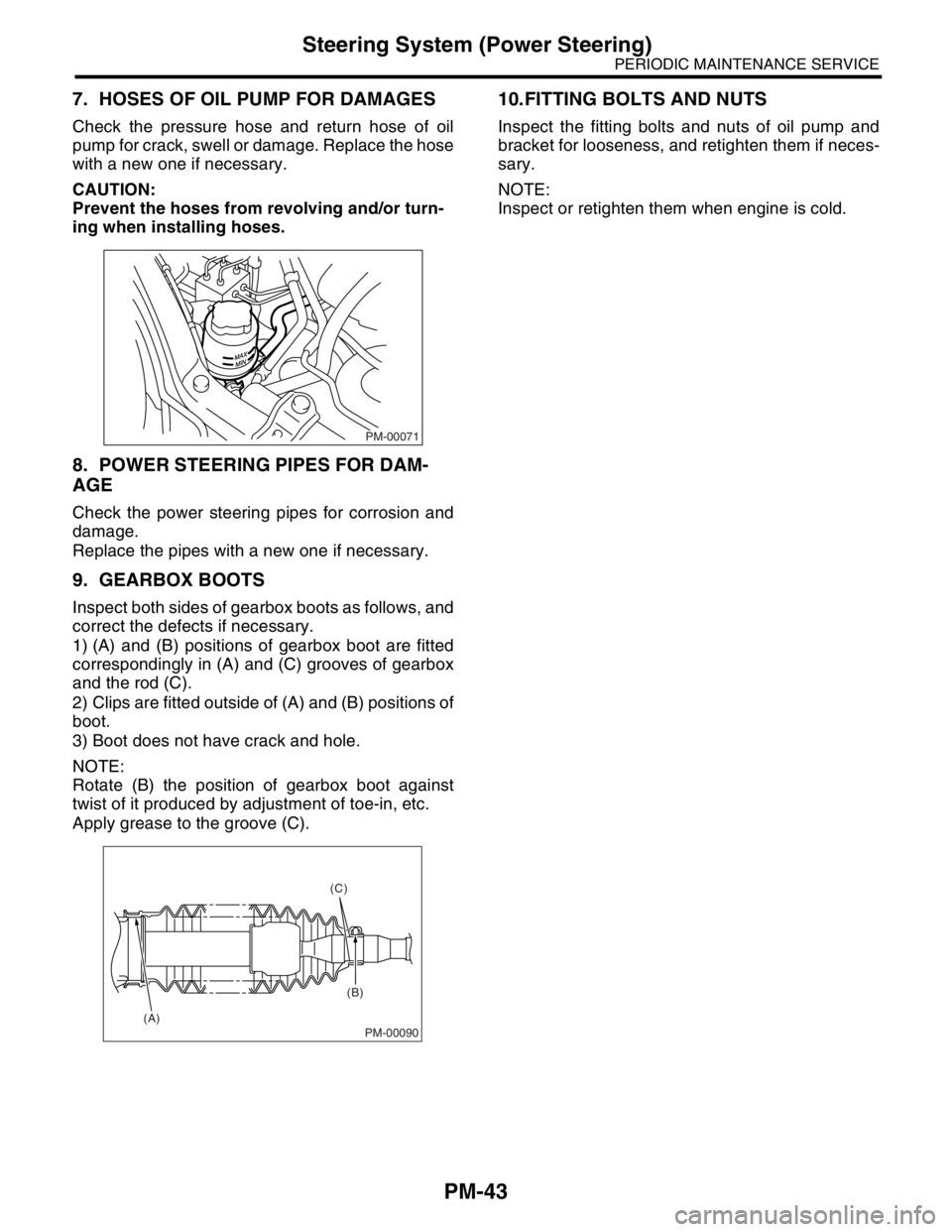
1) (A) and (B) positions of gearbox boot are fitted
correspondingly in (A) and (C) grooves of gearbox
and the rod (C).
2) Clips are fitted outside of (A) and (B) positions of
boot.
3) Boot does not have crack and hole.
NOTE:
Rotate (B) the position of gearbox boot against
twist of it produced by adjustment of toe-in, etc.
Apply grease to the groove (C).
10.FITTING BOLTS AND NUTS
Inspect the fitting bolts and nuts of oil pump and
bracket for looseness, and retighten them if neces-
sary.
NOTE:
Inspect or retighten them when engine is cold.
PM-00071
PM-00090
(C)
(B)
(A)
Page 796 of 2870

FU(H4SO)-14
FUEL INJECTION (FUEL SYSTEM)
Intake Manifold
3. Intake Manifold
A: REMOVAL
1) Release the fuel pressure.
47, RELEASING OF FUEL PRESSURE, OPERA-
TION, Fuel.>
2) Open the fuel flap lid, and remove the fuel filler
cap.
3) Disconnect the ground cable from battery.
4) Remove the air intake duct and air cleaner case.
Case.>
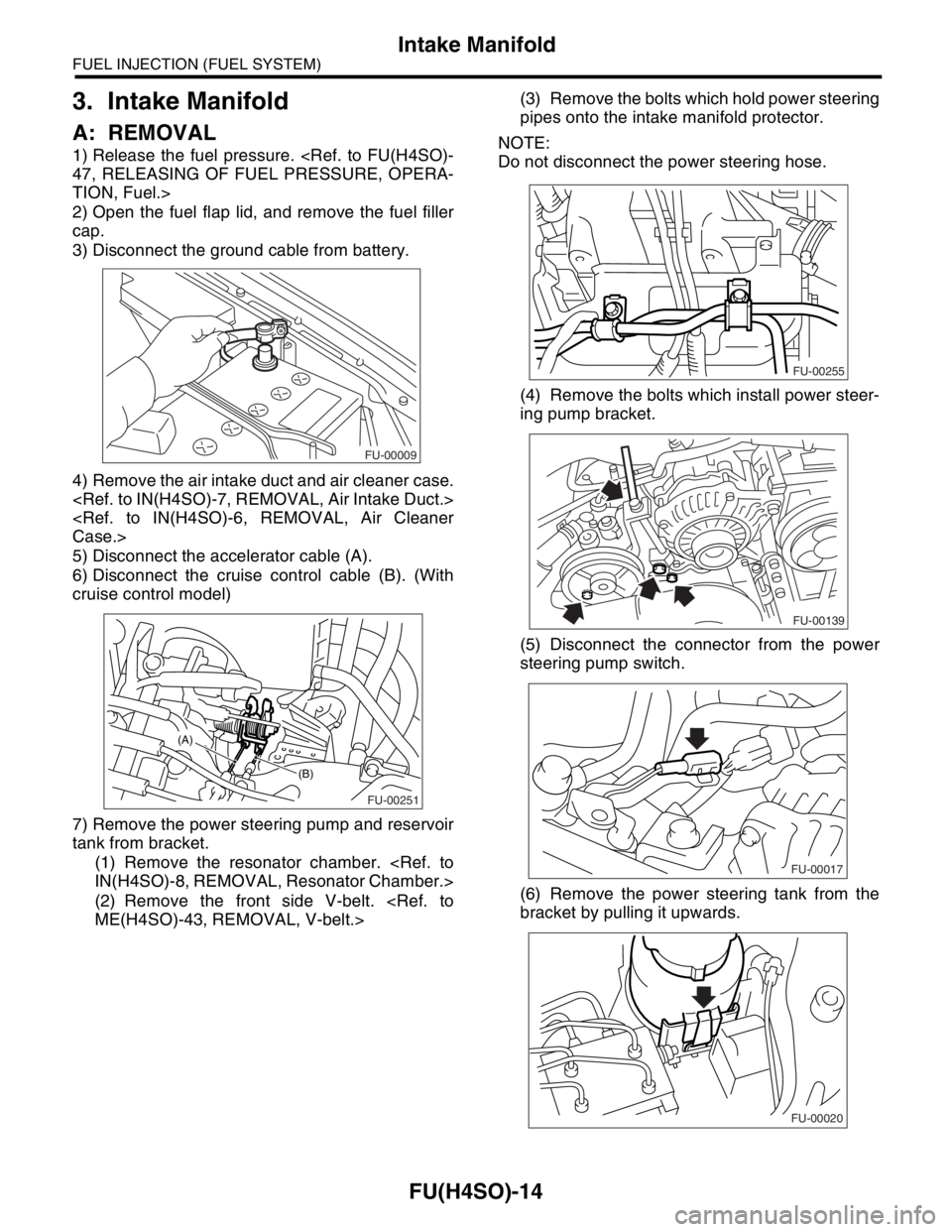
5) Disconnect the accelerator cable (A).
6) Disconnect the cruise control cable (B). (With
cruise control model)
7) Remove the power steering pump and reservoir
tank from bracket.
(1) Remove the resonator chamber.
IN(H4SO)-8, REMOVAL, Resonator Chamber.>
(2) Remove the front side V-belt.
ME(H4SO)-43, REMOVAL, V-belt.>(3) Remove the bolts which hold power steering
pipes onto the intake manifold protector.
NOTE:
Do not disconnect the power steering hose.
(4) Remove the bolts which install power steer-
ing pump bracket.
(5) Disconnect the connector from the power
steering pump switch.
(6) Remove the power steering tank from the
bracket by pulling it upwards.
FU-00009
FU-00251
(B)
(A)
FU-00255
FU-00139
FU-00017
FU-00020
Page 797 of 2870
FU(H4SO)-15
FUEL INJECTION (FUEL SYSTEM)
Intake Manifold
(7) Place the power steering pump on the right
side wheel apron.
8) Disconnect the spark plug cords from the spark
plugs.
9) Disconnect the PCV hose from the intake mani-
fold.
10) Disconnect the engine coolant hose (A) from
the throttle body.
11) Disconnect the brake booster hose.12) Remove the air cleaner case stay RH and en-
gine harness bracket, and disconnect the engine
harness connectors from the bulkhead harness
connectors.
13) Disconnect the connectors from the engine
coolant temperature sensor.
14) Disconnect the knock sensor connector.
15) Disconnect the connector from the crankshaft
position sensor.
FU-00021
FU-00141
FU-00361
(A)(A)
FU-00143
FU-00258
FU-00145
FU-00062
FU-00056
Page 800 of 2870
FU(H4SO)-18
FUEL INJECTION (FUEL SYSTEM)
Intake Manifold
10) Connect the brake booster hose.
11) Connect the engine coolant hose (A) to the
throttle body.
12) Connect the PCV hose to the intake manifold.
13) Connect the spark plug cords to the spark
plugs.
14) Install the power steering pump and reservoir
tank to bracket.
(1) Install the reservoir tank to bracket.(2) Connect the connector to the power steering
pump switch.
(3) Tighten the bolts which install power steer-
ing pump bracket.
Tightening torque:
22 N
⋅m (2.2 kgf-m, 15.9 ft-lb)
(4) Install the power steering pipes onto the
right side intake manifold protector.
(5) Install the front side V-belt.
ME(H4SO)-43, INSTALLATION, V-belt.>
FU-00143
FU-00361
(A)(A)
FU-00141
FU-00020
FU-00017
FU-00139
FU-00255
Page 817 of 2870
FU(H4SO)-35
FUEL INJECTION (FUEL SYSTEM)
Fuel Injector
13.Fuel Injector
A: REMOVAL
1. RH SIDE
1) Release the fuel pressure.
PRESSURE, OPERATION, Fuel.>
2) Open the fuel flap lid, and remove the fuel filler
cap.
3) Disconnect the ground cable from battery.
4) Remove the resonator chamber.
IN(H4SO)-8, REMOVAL, Resonator Chamber.>
5) Remove the spark plug cords from the spark
plugs (#1 and #3 cylinders).6) Remove the power steering pump and reservoir
tank from the brackets.
(1) Remove the front side V-belt.
ME(H4SO)-43, REMOVAL, V-belt.>
(2) Remove the bolts which hold the power
steering pipes onto the intake manifold protec-
tor.
(3) Remove the bolts which install the power
steering pump to the bracket.
(4) Disconnect the connector from the power
steering pump switch.
FU-00009
FU-00302
FU-00255
FU-00139
FU-00017