2004 NISSAN TERRANO maintenance
[x] Cancel search: maintenancePage 1283 of 1833
Precautions
SUPPLEMENTAL RESTRAINT SYSTEM (SRS) ªAIR BAGº AND ªSEAT BELT
PRE-TENSIONERº
The Supplemental Restraint System such as ªAIR BAGº and ªSEAT BELT PRE-TENSIONERº used along with
a seat belt, helps to reduce the risk or severity of injury to the driver and front passenger for certain types of
collision. The SRS composition which is available to NISSAN MODEL R20 is as follows (The composition
varies according to the destination and optional equipment.):
IFor a frontal collision
The Supplemental Restraint System consists of driver air bag module (located in the center of the steer-
ing wheel), front passenger air bag module (located on the instrument panel on passenger side), front seat
belt pre-tensioners, a diagnosis sensor unit, warning lamp, wiring harness and spiral cable.
I For a side collision
The Supplemental Restraint System consists of front side air bag module (located in the outer side of front
seat), side air bag (satellite) sensor, diagnosis sensor unit (one of components of air bags for a frontal
collision), wiring harness, warning lamp (one of components of air bags for a frontal collision).
WARNING:
I To avoid rendering the SRS inoperative, which could increase the risk of personal injury or death
in the event of a collision which would result in air bag inflation, all maintenance should be per-
formed by an authorized NISSAN dealer.
I Improper maintenance, including incorrect removal and installation of the SRS, can lead to per-
sonal injury caused by unintentional activation of the system.
I Do not use electrical test equipment on any circuit related to the SRS unless instructed to in this
Service Manual. Spiral cable and wiring harnesses covered with yellow insulation tape either just
before the harness connectors or for the complete harness are related to the SRS.
PRECAUTIONS FOR SRS ªAIR BAGº AND ªSEAT BELT PRE-TENSIONERº SERVICE
IDo not use electrical test equipment to check SRS circuits unless instructed to in this Service Manual.
I Before servicing the SRS, turn ignition switch ªOFFº, disconnect both battery cables and wait at least 3
minutes.
For approximately 3 minutes after the cables are removed, it is still possible for the air bag and seat belt
pre-tensioner to deploy. Therefore, do not work on any SRS connectors or wires until at least 3 minutes
have passed.
I Diagnosis sensor unit must always be installed with their arrow marks ª +º pointing towards the front of
the vehicle for proper operation. Also check diagnosis sensor unit for cracks, deformities or rust before
installation and replace as required.
I The spiral cable must be aligned with the neutral position since its rotations are limited. Do not attempt to
turn steering wheel or column after removal of steering gear.
I Handle air bag module carefully. Always place driver and front passenger air bag modules with the pad
side facing upward and place front side air bag module (built-in type) standing with stud bolt side setting
bottom.
I Conduct self-diagnosis to check entire SRS for proper function after replacing any components.
I After air bag inflates, the front instrument panel assembly should be replaced if damaged.
WIRING DIAGRAMS AND TROUBLE DIAGNOSIS
When you read wiring diagrams, refer to the following:
IGI-10, ªHOW TO READ WIRING DIAGRAMSº
I EL-8, ªPOWER SUPPLY ROUTINGº for power distribution circuit
When you perform trouble diagnosis, refer to the following:
I GI-25, ªHOW TO FOLLOW TEST GROUPS IN TROUBLE DIAGNOSISº
I GI-22, ªHOW TO PERFORM EFFICIENT DIAGNOSES FOR AN ELECTRICAL INCIDENTº
SUPPLEMENTAL RESTRAINT SYSTEM (SRS)
RS-8
http://vnx.su/
Page 1287 of 1833
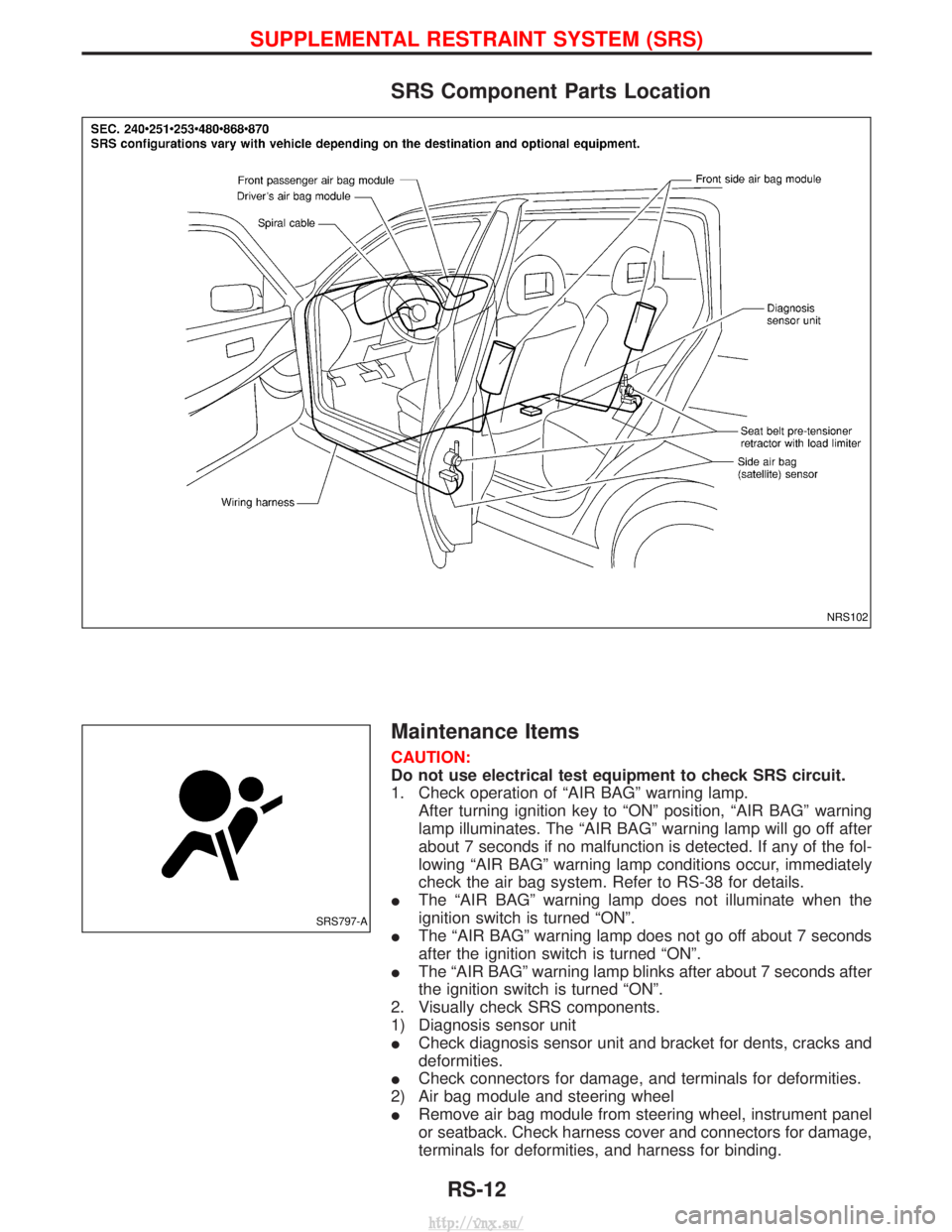
SRS Component Parts Location
Maintenance Items
CAUTION:
Do not use electrical test equipment to check SRS circuit.
1. Check operation of ªAIR BAGº warning lamp.After turning ignition key to ªONº position, ªAIR BAGº warning
lamp illuminates. The ªAIR BAGº warning lamp will go off after
about 7 seconds if no malfunction is detected. If any of the fol-
lowing ªAIR BAGº warning lamp conditions occur, immediately
check the air bag system. Refer to RS-38 for details.
I The ªAIR BAGº warning lamp does not illuminate when the
ignition switch is turned ªONº.
I The ªAIR BAGº warning lamp does not go off about 7 seconds
after the ignition switch is turned ªONº.
I The ªAIR BAGº warning lamp blinks after about 7 seconds after
the ignition switch is turned ªONº.
2. Visually check SRS components.
1) Diagnosis sensor unit
I Check diagnosis sensor unit and bracket for dents, cracks and
deformities.
I Check connectors for damage, and terminals for deformities.
2) Air bag module and steering wheel
I Remove air bag module from steering wheel, instrument panel
or seatback. Check harness cover and connectors for damage,
terminals for deformities, and harness for binding.
NRS102
SRS797-A
SUPPLEMENTAL RESTRAINT SYSTEM (SRS)
RS-12
http://vnx.su/
Page 1288 of 1833
IInstall driver air bag module to steering wheel to check fit or
alignment with the wheel.
I Check steering wheel for excessive free play.
I Install front passenger air bag module to instrument panel to
check fit or alignment with the instrument panel.
I Install front side air bag module to seatback to check fit and
alignment with the seat.
3) Spiral cable
I Check spiral cable for dents, cracks, or deformities.
I Check connectors and protective tape for damage.
I Check steering wheel for noise, binding or heavy operation.
4) Main harness, body harness, side air bag module sub-harness
I Check connectors for poor connections, damage, and terminals
for deformities.
I Check harnesses for binding, chafing or cut.
5) Front seat belt pre-tensioner
I Check harness cover and connectors for damage, terminals for
deformities, and harness for binding.
I Check belts for damage and anchors for loose mounting.
I Check retractor for smooth operation.
I Perform self-diagnosis for seat belt pre-tensioner using ªAIR
BAGº warning lamp or CONSULT-II.
Refer to ªSRS Operation Checkº for details. (RS-38)
6) Side air bag (satellite) sensor
I Check side air bag (satellite) sensor (including bracket portion)
for dents, cracks or deformities.
I Check connectors for damage, and terminals for deformities.
CAUTION:
Replace previously used special bolts and ground bolt with
new ones.
Diagnosis Sensor Unit
REMOVAL AND INSTALLATION
CAUTION:
I Before servicing SRS, turn the ignition switch off, discon-
nect both battery cables and wait at least 3 minutes.
I The special bolts are coated with bonding agent while the
other bolt is for ground. Do not use old bolts after removal;
replace with new ones.
I Check diagnosis sensor unit for proper installation.
I Check diagnosis sensor unit to ensure it is free of
deformities, dents, cracks or rust. If they show any visible
signs of damage, replace them with new ones.
I Check diagnosis sensor unit brackets to ensure they are
free of deformities or rust.
I Replace diagnosis sensor unit if it has been dropped or
sustained an impact.
I After replacement of diagnosis sensor unit, perform self-
diagnosis for SRS. Refer to ªSRS Operation Checkº for
details. (RS-38)
1. Disconnect driver, front passenger and front side air bag mod- ule connectors. Also, disconnect front seat belt pre-tensioner
connector.
2. Remove console box. Refer to BT-22, ªINSTRUMENT PANEL ASSEMBLYº.
3. Disconnect diagnosis sensor unit connector.
4. Remove ground bolt and also remove special bolts using the TAMPER RESISTANT TORX (Size T50), from diagnosis sen-
sor unit.
Then remove the diagnosis sensor unit.
SUPPLEMENTAL RESTRAINT SYSTEM (SRS)
Maintenance Items (Cont'd)
RS-13
http://vnx.su/
Page 1319 of 1833
![NISSAN TERRANO 2004 Service Repair Manual 9. Touch ªBACKº key of CONSULT-II to ªSELECT SYSTEMºscreen. Touch ªSELF-DIAG [PAST]º.
10. Check that no malfunction is detected on ªSELF-DIAG [PAST]º.
11. Touch ªBACKº key of CONSULT-II unti](/manual-img/5/57394/w960_57394-1318.png "NISSAN TERRANO 2004 Service Repair Manual 9. Touch ªBACKº key of CONSULT-II to ªSELECT SYSTEMºscreen. Touch ªSELF-DIAG [PAST]º.
10. Check that no malfunction is detected on ªSELF-DIAG [PAST]º.
11. Touch ªBACKº key of CONSULT-II unti")
9. Touch ªBACKº key of CONSULT-II to ªSELECT SYSTEMºscreen. Touch ªSELF-DIAG [PAST]º.
10. Check that no malfunction is detected on ªSELF-DIAG [PAST]º.
11. Touch ªBACKº key of CONSULT-II until ªSELECT SYSTEMº appears in order to return to User mode from Diagnosis mode.
12. Turn ignition switch ªOFFº, then turn off and disconnect CON- SULT-II.
13. Go to ªSRS Operation Checkº, page RS-38 to check SRS operation by using ªAIR BAGº warning lamp with User mode.
DIAGNOSTIC PROCEDURE 4 (CONTINUED FROM
DIAGNOSTIC PROCEDURE 2)
Inspecting SRS malfunctioning record
1 CONSIDER POSSIBILITY OF NOT ERASING SELF-DIAGNOSTIC RESULT AFTER REPAIRING
Is it the first time for maintenance of SRS?
YesorNo
Ye s EGo to DIAGNOSTIC PROCEDURE 5 (RS-44).
No ESelf-diagnostic result ªSELF-DIAG [PAST]º (previously stored in the memory) might not be erased after repair. Go
to DIAGNOSTIC PROCEDURE 3, step 8 (RS-42).
DIAGNOSTIC PROCEDURE 5
Inspecting SRS intermittent malfunction by using CONSULT-II
Ð Diagnosis mode
1. Turn ignition switch ªOFFº.
2. Connect CONSULT-II to data link connector.
SRS697
SRS702
NRS122
SUPPLEMENTAL RESTRAINT SYSTEM (SRS)
Trouble Diagnoses with CONSULT-II (Cont'd)
RS-44
http://vnx.su/
Page 1331 of 1833
DIAGNOSTIC PROCEDURE 8 (CONTINUED FROM
DIAGNOSTIC PROCEDURE 6)
Inspecting SRS malfunctioning record
1 CONSIDER POSSIBILITY OF NOT ERASING SELF-DIAGNOSTIC RESULT AFTER REPAIRING
Is it the first time for maintenance of SRS?YesorNo
Ye s EGo to DIAGNOSTIC PROCEDURE 5 (RS-44). (Further inspection cannot be performed without CONSULT-II.)
No EDiagnosis results (previously stored in the memory) might not be erased after repair. Go to DIAGNOSTIC PRO-
CEDURE 7, step 5 (RS-53).
Trouble Diagnoses: ªAIR BAGº Warning Lamp
Does Not Turn Off
DIAGNOSTIC PROCEDURE 9
1 SEE THE DEPLOYMENT OF AIR BAG MODULE
Is air bag module deployed?
YesorNo
Ye s ERefer to COLLISION DIAGNOSIS (RS-59).
No EGO TO 2.
2 CHECK AIR BAG FUSE
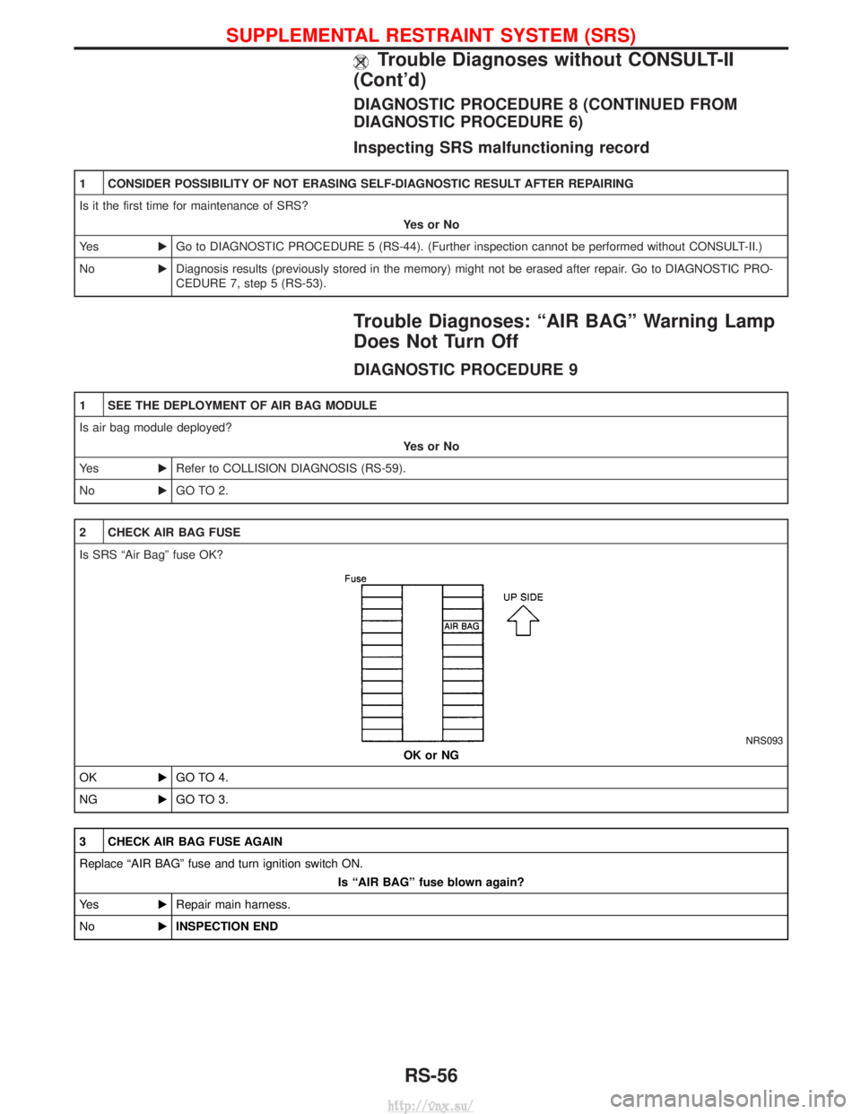
Is SRS ªAir Bagº fuse OK?
NRS093
OK or NG
OK EGO TO 4.
NG EGO TO 3.
3 CHECK AIR BAG FUSE AGAIN
Replace ªAIR BAGº fuse and turn ignition switch ON.
Is ªAIR BAGº fuse blown again?
Ye s ERepair main harness.
No EINSPECTION END
SUPPLEMENTAL RESTRAINT SYSTEM (SRS)
Trouble Diagnoses without CONSULT-II
(Cont'd)
RS-56
http://vnx.su/
Page 1338 of 1833
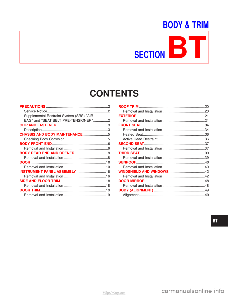
BODY & TRIM
SECTION
BT
CONTENTS
PRECAUTIONS ...............................................................2
Service Notice..............................................................2
Supplemental Restraint System (SRS) ²AIR
BAG² and²SEAT BELT PRE-TENSIONER² ...............2
CLIP AND FASTENER ....................................................3
Description ...................................................................3
CHASSIS AND BODY MAINTENANCE .........................5
Checking Body Corrosion ............................................5
BODY FRONT END .........................................................6
Removal and Installation .............................................6
BODY REAR END AND OPENER ..................................8
Removal and Installation .............................................8
DOOR ........................................................................\
.....10
Removal and Installation ...........................................10
INSTRUMENT PANEL ASSEMBLY ..............................16
Removal and Installation ...........................................16
SIDE AND FLOOR TRIM ..............................................18
Removal and Installation ...........................................18
DOOR TRIM ...................................................................19
Removal and Installation ...........................................19 ROOF TRIM
...................................................................20
Removal and Installation ...........................................20
EXTERIOR .....................................................................21
Removal and Installation ...........................................21
FRONT SEAT .................................................................34
Removal and Installation ...........................................34
Heated Seat ...............................................................36
Active Head Restraint ................................................36
SECOND SEAT ..............................................................37
Removal and Installation ...........................................37
THIRD SEAT ..................................................................39
Removal and Installation ...........................................39
SUNROOF ......................................................................40
Removal and Installation ...........................................40
WINDSHIELD AND WINDOWS ....................................42
Removal and Installation ...........................................42
DOOR MIRROR .............................................................48
Removal and Installation ...........................................48
BODY (ALIGNMENT) ....................................................49
Alignment ...................................................................49
http://vnx.su/
Page 1339 of 1833
Service Notice
IWhen removing or installing various parts, place a cloth or padding onto the vehicle body to prevent
scratches.
I Handle trim, molding, instruments, grille, etc. carefully during removing or installing. Be careful not to oil
or damage them.
I Apply sealing compound where necessary when installing parts.
I When applying sealing compound, be careful that the sealing compound does not protrude from parts.
I When replacing any metal parts (for example body outer panel, members, etc.), be sure to take rust pre-
vention measures.
Supplemental Restraint System (SRS) ªAIR
BAGº and ªSEAT BELT PRE-TENSIONERº
The Supplemental Restraint System such as ªAIR BAGº and ªSEAT BELT PRE-TENSIONERº used along with
a seat belt, helps to reduce the risk or severity of injury to the driver and front passenger for certain types of
collision. The SRS system composition which is available to NISSAN MODEL R20 is as follows (The compo-
sition varies according to the destination and optional equipment.):
IFor a frontal collision
The Supplemental Restraint System consists of driver air bag module (located in the center of the steer-
ing wheel), front passenger air bag module (located on the instrument panel on passenger side), front seat
belt pre-tensioners, a diagnosis sensor unit, warning lamp, wiring harness and spiral cable.
I For a side collision
The Supplemental Restraint System consists of front side air bag module (located in the outer side of front
seat), side air bag (satellite) sensor, diagnosis sensor unit (one of components of air bags for a frontal
collision), wiring harness, warning lamp (one of components of air bags for a frontal collision).
Information necessary to service the system safely is included in the RSsection of this Service Manual.
WARNING:
I To avoid rendering the SRS inoperative, which could increase the risk of personal injury or death
in the event of a collision which would result in air bag inflation, all maintenance should be per-
formed by an authorized NISSAN dealer.
I Improper maintenance, including incorrect removal and installation of the SRS, can lead to per-
sonal injury caused by unintentional activation of the system. For removal of Spiral Cable and Air
Bag Module, see the RS section.
I Do not use electrical test equipment on any circuit related to the SRS unless instructed to in this
Service Manual. Spiral cable and wiring harnesses covered with yellow insulation tape either just
before the harness connectors or for the complete harness are related to the SRS.
PRECAUTIONS
BT-2
http://vnx.su/
Page 1342 of 1833
Checking Body Corrosion
Visually check the body sheet metal panel for corrosion, paint damage (scratches, chipping, rubbing, etc.) or
damage to the anti-corrosion materials. In particular, check the following locations.
Hemmed portion
Hood front end, door lower end, back door rear end, etc.
Panel joint
Side sill of rear fender and center pillar, rear wheel housing of rear fender, around strut tower in engine
compartment, etc.
Panel edge
Back door opening, sunroof opening, fender wheelarch flange, fuel filler lid flange, around holes in panel, etc.
Parts contact
Waist molding, windshield molding, bumper, etc.
Protectors
Damage or condition of mudguard, fender protector, chipping protector, etc.
Anti-corrosion materials
Damage or separation of anti-corrosion materials under the body.
Drain holes
Condition of drain holes at door and side sill.
When repairing corroded areas, refer to the Corrosion Repair Manual.
CHASSIS AND BODY MAINTENANCE
BT-5
http://vnx.su/