2004 NISSAN TERRANO maintenance
[x] Cancel search: maintenancePage 637 of 1833
qA
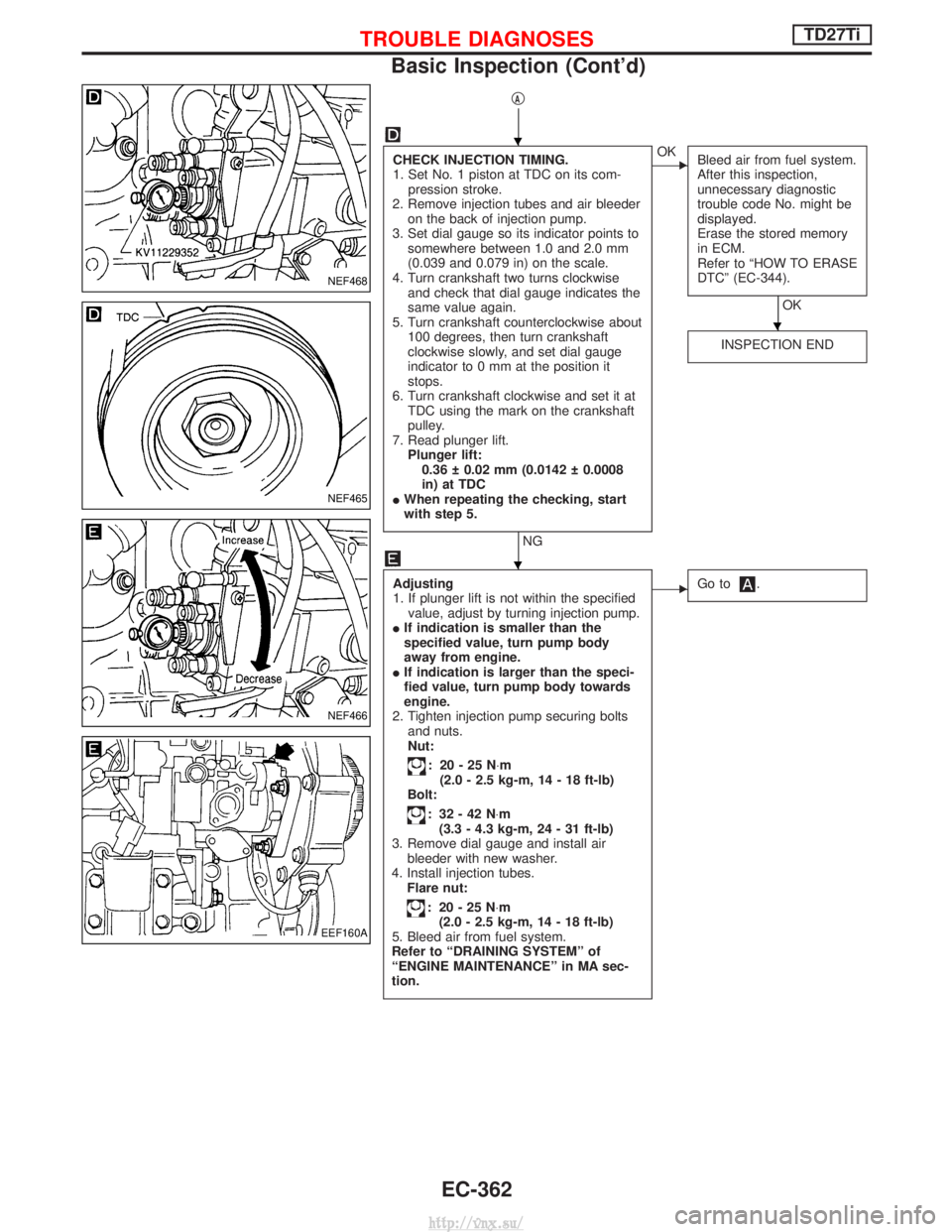
CHECK INJECTION TIMING.
1. Set No. 1 piston at TDC on its com-pression stroke.
2. Remove injection tubes and air bleeder on the back of injection pump.
3. Set dial gauge so its indicator points to somewhere between 1.0 and 2.0 mm
(0.039 and 0.079 in) on the scale.
4. Turn crankshaft two turns clockwise and check that dial gauge indicates the
same value again.
5. Turn crankshaft counterclockwise about 100 degrees, then turn crankshaft
clockwise slowly, and set dial gauge
indicator to 0 mm at the position it
stops.
6. Turn crankshaft clockwise and set it at TDC using the mark on the crankshaft
pulley.
7. Read plunger lift. Plunger lift:0.36 0.02 mm (0.0142 0.0008
in) at TDC
I When repeating the checking, start
with step 5.
NG
EOK
Bleed air from fuel system.
After this inspection,
unnecessary diagnostic
trouble code No. might be
displayed.
Erase the stored memory
in ECM.
Refer to ªHOW TO ERASE
DTCº (EC-344).
OK
INSPECTION END
Adjusting
1. If plunger lift is not within the specified value, adjust by turning injection pump.
I If indication is smaller than the
specified value, turn pump body
away from engine.
I If indication is larger than the speci-
fied value, turn pump body towards
engine.
2. Tighten injection pump securing bolts and nuts.
Nut:
: 20-25N ×m
(2.0 - 2.5 kg-m, 14 - 18 ft-lb)
Bolt:
: 32-42N ×m
(3.3 - 4.3 kg-m, 24 - 31 ft-lb)
3. Remove dial gauge and install air bleeder with new washer.
4. Install injection tubes. Flare nut:
: 20-25N ×m
(2.0 - 2.5 kg-m, 14 - 18 ft-lb)
5. Bleed air from fuel system.
Refer to ªDRAINING SYSTEMº of
ªENGINE MAINTENANCEº in MA sec-
tion.
EGo to.
NEF468
NEF465
NEF466
EEF160A
H
H
H
TROUBLE DIAGNOSESTD27Ti
Basic Inspection (Cont'd)
EC-362
http://vnx.su/
Page 817 of 1833
Supplemental Restraint System (SRS) ªAIR
BAGº and ªSEAT BELT PRE-TENSIONERº
The Supplemental Restraint System such as ªAIR BAGº and ªSEAT BELT PRE-TENSIONERº used along with
a seat belt, helps to reduce the risk or severity of injury to the driver and front passenger for certain types of
collision. The SRS composition which is available to NISSAN MODEL R20 is as follows (The composition
varies according to the destination and optional equipment.):
IFor a frontal collision
The Supplemental Restraint System consists of driver air bag module (located in the center of the steer-
ing wheel), front passenger air bag module (located on the instrument panel on passenger side), front seat
belt pre-tensioners, a diagnosis sensor unit, warning lamp, wiring harness and spiral cable.
I For a side collision
The Supplemental Restraint System consists of front side air bag module (located in the outer side of front
seat), side air bag (satellite) sensor, diagnosis sensor unit (one of components of air bags for a frontal
collision), wiring harness, warning lamp (one of components of air bags for a frontal collision).
WARNING:
I To avoid rendering the SRS inoperative, which could increase the risk of personal injury or death
in the event of a collision which would result in air bag inflation, all maintenance should be per-
formed by an authorized NISSAN dealer.
I Improper maintenance, including incorrect removal and installation of the SRS, can lead to per-
sonal injury caused by unintentional activation of the system.
I Do not use electrical test equipment on any circuit related to the SRS unless instructed to in this
Service Manual. Spiral cable and wiring harnesses covered with yellow insulation tape either just
before the harness connectors or for the complete harness are related to the SRS.
Precautions for SRS ªAIR BAGº and ªSEAT
BELT PRE-TENSIONERº Service
IDo not use electrical test equipment to check SRS circuits unless instructed to in this Service Manual.
I Before servicing the SRS, turn ignition switch ªOFFº, disconnect both battery cables and wait at least 3
minutes.
For approximately 3 minutes after the cables are removed, it is still possible for the air bag and seat belt
pre-tensioner to deploy. Therefore, do not work on any SRS connectors or wires until at least 3 minutes
have passed.
I Diagnosis sensor unit must always be installed with their arrow marks ª +º pointing towards the front of
the vehicle for proper operation. Also check diagnosis sensor unit for cracks, deformities or rust before
installation and replace as required.
I The spiral cable must be aligned with the neutral position since its rotations are limited. Do not attempt to
turn steering wheel or column after removal of steering gear.
I Handle air bag module carefully. Always place driver and front passenger air bag modules with the pad
side facing upward and place front side air bag module (built-in type) standing with stud bolt side setting
bottom.
I Conduct self-diagnosis to check entire SRS for proper function after replacing any components.
I After air bag inflates, the front instrument panel assembly should be replaced if damaged.
Precautions
IBefore proceeding with disassembly, thoroughly clean the outside of the transmission. It is important to
prevent the internal parts from becoming contaminated by dirt or other foreign matter.
I Disassembly should be done in a clean work area.
I Use lint-free cloth or towels for wiping parts clean. Common shop rags can leave fibers that could inter-
fere with the operation of the transmission.
I Place disassembled parts in order for easier and proper assembly.
I All parts should be carefully cleaned with a general purpose, non-flammable solvent before inspection or
reassembly.
I Gaskets, seals and O-rings should be replaced any time the transmission is disassembled.
I It is very important to perform functional tests whenever they are indicated.
I The valve body contains precision parts and requires extreme care when parts are removed and serviced.
Place removed parts in a parts rack in order to replace them in correct positions and sequences. Care will
also prevent springs and small parts from becoming scattered or lost.
I Properly installed valves, sleeves, plugs, etc. will slide along bores in valve body under their own weight.
PREPARATION AND PRECAUTIONS
AT- 4
http://vnx.su/
Page 840 of 1833

A/T Fluid Check
FLUID LEAKAGE CHECK
1. Clean area suspected of leaking. Ð for example, mating sur-face of converter housing and transmission case.
2. Start engine, apply foot brake, place selector lever in ªDº posi- tion and wait a few minutes.
3. Stop engine.
4. Check for fresh leakage.
FLUID CONDITION CHECK
Fluid color Suspected cause
Dark or black with burned odor Wear of frictional material
Milky pink Water contamination Ð Road water enter-
ing through filler tube or breather
Varnished fluid, light to dark
brown and tacky Oxidation Ð Over or under filling, Ð Over-
heating
FLUID LEVEL CHECK
Refer to MA section (ªChecking A/T Fluidº, ªCHASSIS AND BODY
MAINTENANCEº).
Stall Test
STALL TEST PROCEDURE
1. Check A/T and engine fluid levels. If necessary, add.
2. Drive vehicle for approx. 10 minutes or until engine oil and ATF
reach operating temperature.ATF operating temperature: 50 - 80ÉC (122 - 176ÉF)
3. Set parking brake and block wheels.
4. Install a tachometer where it can be seen by driver during test.
I It is good practice to put a mark on point of specified
engine rpm on indicator.
5. Start engine, apply foot brake, and place selector lever in ªDº position.
6. Accelerate to wide open throttle gradually while applying foot brake.
7. Quickly note the engine stall revolution and immediately release throttle.
I During test, never hold throttle wide open for more than 5
seconds.
Stall revolution: 2,450 - 2,700 rpm
SAT801A
SAT638A
SAT647B
SAT513G
SAT514G
TROUBLE DIAGNOSIS Ð Basic Inspection
AT-27
http://vnx.su/
Page 1013 of 1833
A/T Fluid Cooler
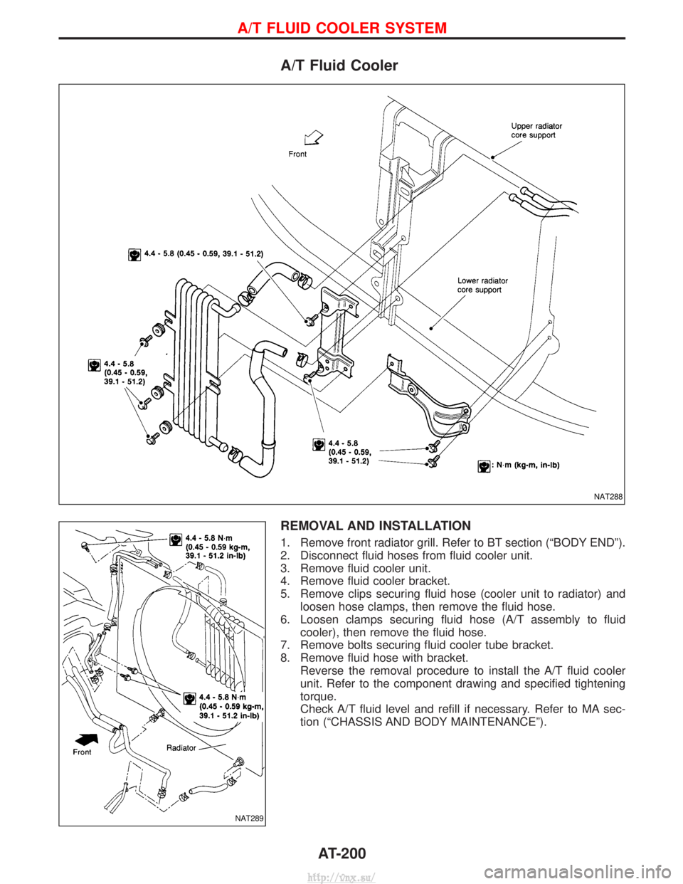
REMOVAL AND INSTALLATION
1. Remove front radiator grill. Refer to BT section (ªBODY ENDº).
2. Disconnect fluid hoses from fluid cooler unit.
3. Remove fluid cooler unit.
4. Remove fluid cooler bracket.
5. Remove clips securing fluid hose (cooler unit to radiator) andloosen hose clamps, then remove the fluid hose.
6. Loosen clamps securing fluid hose (A/T assembly to fluid cooler), then remove the fluid hose.
7. Remove bolts securing fluid cooler tube bracket.
8. Remove fluid hose with bracket. Reverse the removal procedure to install the A/T fluid cooler
unit. Refer to the component drawing and specified tightening
torque.
Check A/T fluid level and refill if necessary. Refer to MA sec-
tion (ªCHASSIS AND BODY MAINTENANCEº).
NAT288
NAT289
A/T FLUID COOLER SYSTEM
AT-200
http://vnx.su/
Page 1170 of 1833
Supplement Restraint System (SRS) ªAIR BAGº
and ªSEAT BELT PRE-TENSIONERº
The Supplemental Restraint System ªAir Bagº and ªSeat Belt Pre-tensionerº, used along with a seat belt, help
to reduce the risk or severity or injury to the driver and front passenger in a collision. The Supplemental
Restraint System consists of an air bag module (located in the center of the steering wheel and on the instru-
ment panel on the passenger side, where fitted), seat belt pre-tensioners, a diagnosis sensor unit, warning
lamp, wiring harness and spiral cable. Information necessary to service the system safely is included in the
BT sectionof this Service Manual.
WARNING:
I To avoid rendering the SRS inoperative (which could increase the risk of personal injury or death
in the event of a collision which would result in air bag inflation), all maintenance must be per-
formed by an authorized NISSAN dealer.
I Improper maintenance, including incorrect removal and installation of the SRS, can lead to per-
sonal injury caused by unintentional activation of the system.
I Do not use electrical test equipment on any circuit related to the SRS unless instructed to in this
Service Manual. SRS wiring harnesses (except ªSEAT BELT-TENSIONERº connector) can be iden-
tified with yellow harness connector and with yellow harness protector or yellow insulation tape
before the harness connectors.
Precautions
IUse only ªDOT 4º fluid from a sealed container.
I Never reuse drained brake fluid.
I Be careful not to splash brake fluid on painted areas; it
may cause paint damage. If brake fluid is splashed on
painted areas, wash it away with water immediately.
I To clean master cylinder parts, disc brake caliper parts or
wheel cylinder parts, use clean brake fluid.
I Never use mineral oils such as Petrol or kerosene. They
will ruin rubber parts of hydraulic system.
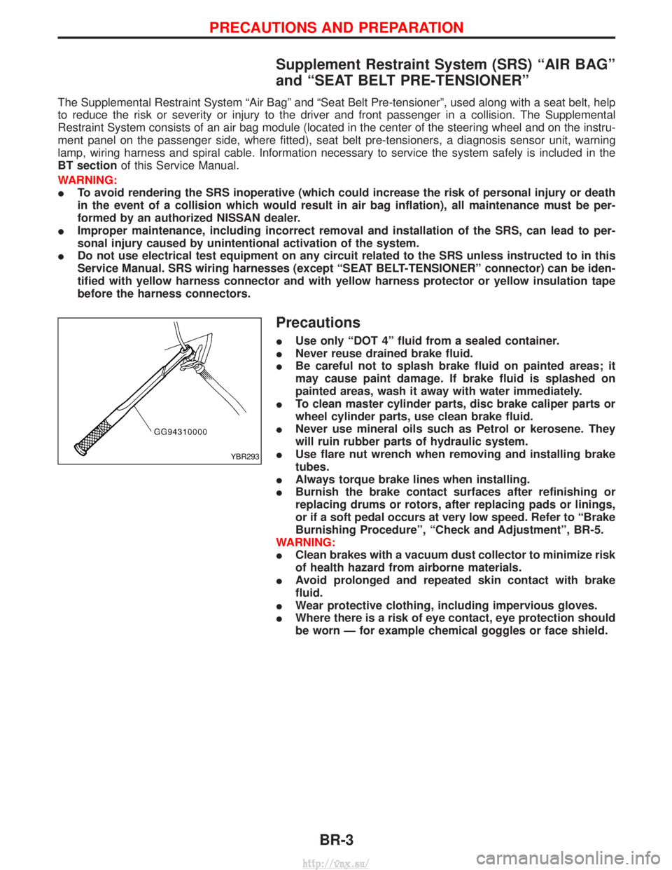
I Use flare nut wrench when removing and installing brake
tubes.
I Always torque brake lines when installing.
I Burnish the brake contact surfaces after refinishing or
replacing drums or rotors, after replacing pads or linings,
or if a soft pedal occurs at very low speed. Refer to ªBrake
Burnishing Procedureº, ªCheck and Adjustmentº, BR-5.
WARNING:
I Clean brakes with a vacuum dust collector to minimize risk
of health hazard from airborne materials.
I Avoid prolonged and repeated skin contact with brake
fluid.
I Wear protective clothing, including impervious gloves.
I Where there is a risk of eye contact, eye protection should
be worn Ð for example chemical goggles or face shield.
YBR293
PRECAUTIONS AND PREPARATION
BR-3
http://vnx.su/
Page 1255 of 1833
Supplemental Restraint System (SRS) ªAIR
BAGº and ªSEAT BELT PRE-TENSIONERº
The Supplemental Restraint System such as ªAIR BAGº and ªSEAT BELT PRE-TENSIONERº used along with
a seat belt, helps to reduce the risk or severity of injury to the driver and front passenger for certain types of
collision. The SRS composition which is available to NISSAN MODEL R20 is as follows (The composition
varies according to the destination and optional equipment.):
IFor a frontal collision
The Supplemental Restraint System consists of driver air bag module (located in the center of the steer-
ing wheel), front passenger air bag module (located on the instrument panel on passenger side), front seat
belt pre-tensioners, a diagnosis sensor unit, warning lamp, wiring harness and spiral cable.
I For a side collision
The Supplemental Restraint System consists of front side air bag module (located in the outer side of front
seat), side air bag (satellite) sensor, diagnosis sensor unit (one of components of air bags for a frontal
collision), wiring harness, warning lamp (one of components of air bags for a frontal collision).
WARNING:
I To avoid rendering the SRS inoperative, which could increase the risk of personal injury or death
in the event of a collision which would result in air bag inflation, all maintenance should be per-
formed by an authorized NISSAN dealer.
I Improper maintenance, including incorrect removal and installation of the SRS, can lead to per-
sonal injury caused by unintentional activation of the system.
I Do not use electrical test equipment on any circuit related to the SRS unless instructed to in this
Service Manual. Spiral cable and wiring harnesses covered with yellow insulation tape either just
before the harness connectors or for the complete harness are related to the SRS.
Precautions for SRS ªAIR BAGº and ªSEAT
BELT PRE-TENSIONERº Service
IDo not use electrical test equipment to check SRS circuits unless instructed to in this Service Manual.
I Before servicing the SRS, turn ignition switch ªOFFº, disconnect both battery cables and wait at least 3
minutes.
For approximately 3 minutes after the cables are removed, it is still possible for the air bag and seat belt
pre-tensioner to deploy. Therefore, do not work on any SRS connectors or wires until at least 3 minutes
have passed.
I Diagnosis sensor unit must always be installed with their arrow marks ª +º pointing towards the front of
the vehicle for proper operation. Also check diagnosis sensor unit for cracks, deformities or rust before
installation and replace as required.
I The spiral cable must be aligned with the neutral position since its rotations are limited. Do not attempt to
turn steering wheel or column after removal of steering gear.
I Handle air bag module carefully. Always place driver and front passenger air bag modules with the pad
side facing upward and place front side air bag module (built-in type) standing with stud bolt side setting
bottom.
I Conduct self-diagnosis to check entire SRS for proper function after replacing any components.
I After air bag inflates, the front instrument panel assembly should be replaced if damaged.
Precautions for Steering System
IBefore disassembly, thoroughly clean the outside of the unit.
I Disassembly should be done in a clean work area. It is important to prevent the internal parts from
becoming contaminated by dirt or other foreign matter.
I When disassembling parts, be sure to place them in order on a part rack so they can be reinstalled
in their proper positions.
I Use nylon cloths or paper towels to clean the parts; common shop rags can leave lint that might
interfere with their operation.
I Before inspection or reassembly, carefully clean all parts with a general purpose, non-flammable
solvent.
I Before assembly, apply a coat of recommended ATF* to hydraulic parts. Vaseline may be applied
to O-rings and seals. Do not use any grease.
I Replace all gaskets, seals and O-rings. Avoid damaging O-rings, seals and gaskets during instal-
lation. Perform functional tests whenever designated.
*: Automatic transmission fluid
PRECAUTIONS
ST-2
http://vnx.su/
Page 1276 of 1833
RESTRAINT SYSTEM
SECTION
RS
CONTENTS
SEAT BELTS ...................................................................2
Precautions ..................................................................2
Front Seat Belt.............................................................4
Rear Seat Belt .............................................................6
SUPPLEMENTAL RESTRAINT SYSTEM (SRS) ............8
Precautions ..................................................................8
Preparation ..................................................................9
SRS Configuration .....................................................10
Seat Belt Pre-tensioner with Load Limiter................. 11
Built-in Type Side Air Bag.......................................... 11
SRS Component Parts Location ...............................12
Maintenance Items ....................................................12
Diagnosis Sensor Unit ...............................................13
Front Seat Belt Pre-tensioner ....................................14
Side Air Bag (Satellite) Sensor ..................................15
Driver Air Bag Module and Spiral Cable ...................16
Front Passenger Air Bag Module ..............................19 Front Side Air Bag Module ........................................20
Disposal of Air Bag Module and Seat Belt Pre-
tensioner ....................................................................22
Trouble Diagnoses Introduction.................................28
How to Perform Trouble Diagnoses for Quick
and Accurate Repair ..................................................31
Schematic ..................................................................33
Wiring Diagram - SRS -.............................................34
SRS Operation Check ...............................................38
Trouble Diagnoses with CONSULT-II..................39
Trouble Diagnoses without CONSULT-II.............48
Trouble Diagnoses: ²AIR BAG² Warning Lamp
Does Not Turn Off .....................................................56
Trouble Diagnoses: ²AIR BAG² Warning Lamp
Does Not Turn On .....................................................58
Collision Diagnosis ....................................................59
http://vnx.su/
Page 1277 of 1833
Precautions
SUPPLEMENTAL RESTRAINT SYSTEM (SRS) ªAIR BAGº AND ªSEAT BELT
PRE-TENSIONERº
The Supplemental Restraint System such as ªAIR BAGº and ªSEAT BELT PRE-TENSIONERº used along with
a seat belt, helps to reduce the risk or severity of injury to the driver and front passenger for certain types of
collision. The SRS composition which is available to NISSAN MODEL R20 is as follows (The composition
varies according to the destination and optional equipment.):
IFor a frontal collision
The Supplemental Restraint System consists of driver air bag module (located in the center of the steer-
ing wheel), front passenger air bag module (located on the instrument panel on passenger side), front seat
belt pre-tensioners, a diagnosis sensor unit, warning lamp, wiring harness and spiral cable.
I For a side collision
The Supplemental Restraint System consists of front side air bag module (located in the outer side of front
seat), side air bag (satellite) sensor, diagnosis sensor unit (one of components of air bags for a frontal
collision), wiring harness, warning lamp (one of components of air bags for a frontal collision).
WARNING:
I To avoid rendering the SRS inoperative, which could increase the risk of personal injury or death
in the event of a collision which would result in air bag inflation, all maintenance should be per-
formed by an authorized NISSAN dealer.
I Improper maintenance, including incorrect removal and installation of the SRS, can lead to per-
sonal injury caused by unintentional activation of the system.
I Do not use electrical test equipment on any circuit related to the SRS unless instructed to in this
Service Manual. Spiral cable and wiring harnesses covered with yellow insulation tape either just
before the harness connectors or for the complete harness are related to the SRS.
Precaution for Seat Belt Service
CAUTION:
IBefore removing the seat belt pre-tensioner assembly, turn the ignition switch off, disconnect both
battery cables and wait at least 3 minutes.
I Do not use electrical test equipment for seat belt pre-tensioner connector.
I After replacing or reinstalling seat belt pre-tensioner assembly, or reconnecting seat belt pre-ten-
sioner connector, check the system function. Refer to ªSRS Operation Checkº for details. (RS-38)
I Do not disassemble buckle or seat belt assembly.
I Replace anchor bolts if they are deformed or worn out.
I Never oil tongue and buckle.
I If any component of seat belt assembly is questionable, do not repair. Replace the whole seat belt
assembly.
I If webbing is cut, frayed, or damaged, replace seat belt assembly.
I When replacing seat belt assembly, use a genuine seat belt assembly.
After A Collision
WARNING:
Inspect all seat belt assemblies including retractors and attaching hardware after any collision.
NISSAN recommends that all seat belt assemblies in use during a collision be replaced unless the
collision was minor and the belts show no damage and continue to operate properly. Failure to do so
could result in serious personal injury in an accident. Seat belt assemblies not in use during a colli-
sion should also be replaced if either damage or improper operation is noted. Seat belt pre-tensioner
should be replaced even if the seat belts are not in use during a frontal collision in which the air bags
are deployed.
Replace any seat belt assembly if:
IThe seat belt was in use at the time of a collision (except for minor collisions and the belts, retractors and
buckles show no damage and continue to operate properly).
I The seat belt was damaged in an accident. (i.e. torn webbing, bent retractor or guide, etc.)
I The seat belt attaching point was damaged in an accident. Inspect the seat belt attaching area for dam-
age or distortion and repair as necessary before installing a new seat belt assembly.
I Anchor bolts are deformed or worn out.
SEAT BELTS
RS-2
http://vnx.su/