2004 NISSAN TERRANO Pressure
[x] Cancel search: PressurePage 335 of 1833
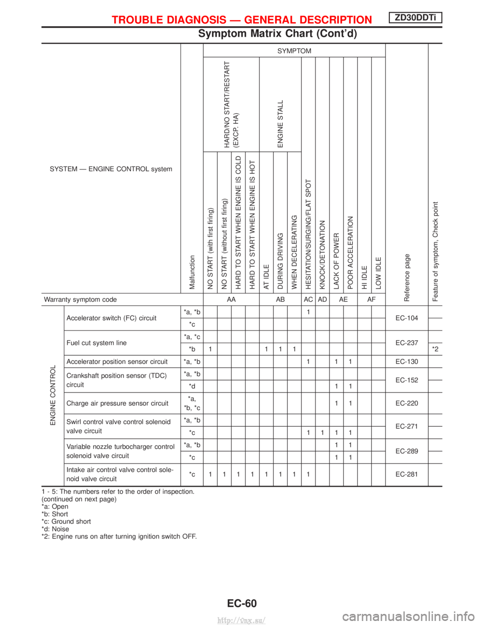
SYSTEM Ð ENGINE CONTROL system
Malfunction
SYMPTOM
Reference page
Feature of symptom, Check pointHARD/NO START/RESTART
(EXCP. HA)
ENGINE STALL
HESITATION/SURGING/FLAT SPOT
KNOCK/DETONATION
LACK OF POWER
POOR ACCELERATION
HI IDLE
LOW IDLE NO START (with first firing)
NO START (without first firing)
HARD TO START WHEN ENGINE IS COLD
HARD TO START WHEN ENGINE IS HOT
AT IDLE
DURING DRIVING
WHEN DECELERATINGWarranty symptom code AAAB AC AD AE AF
ENGINE CONTROL
Accelerator switch (FC) circuit *a, *b 1
EC-104
*c
Fuel cut system line *a, *c
EC-237
*b 1 1 1 1 *2
Accelerator position sensor circuit *a, *b 1 1 1 EC-130
Crankshaft position sensor (TDC)
circuit *a, *b
EC-152
*d 1 1
Charge air pressure sensor circuit *a,
*b, *c 1 1 EC-220
Swirl control valve control solenoid
valve circuit *a, *b
EC-271
*c 1111
Variable nozzle turbocharger control
solenoid valve circuit *a, *b 1 1
EC-289
*c 1 1
Intake air control valve control sole-
noid valve circuit *c 11111111
EC-281
1 - 5: The numbers refer to the order of inspection.
(continued on next page)
*a: Open
*b: Short
*c: Ground short
*d: Noise
*2: Engine runs on after turning ignition switch OFF.
TROUBLE DIAGNOSIS Ð GENERAL DESCRIPTIONZD30DDTi
Symptom Matrix Chart (Cont'd)
EC-60
http://vnx.su/
Page 336 of 1833
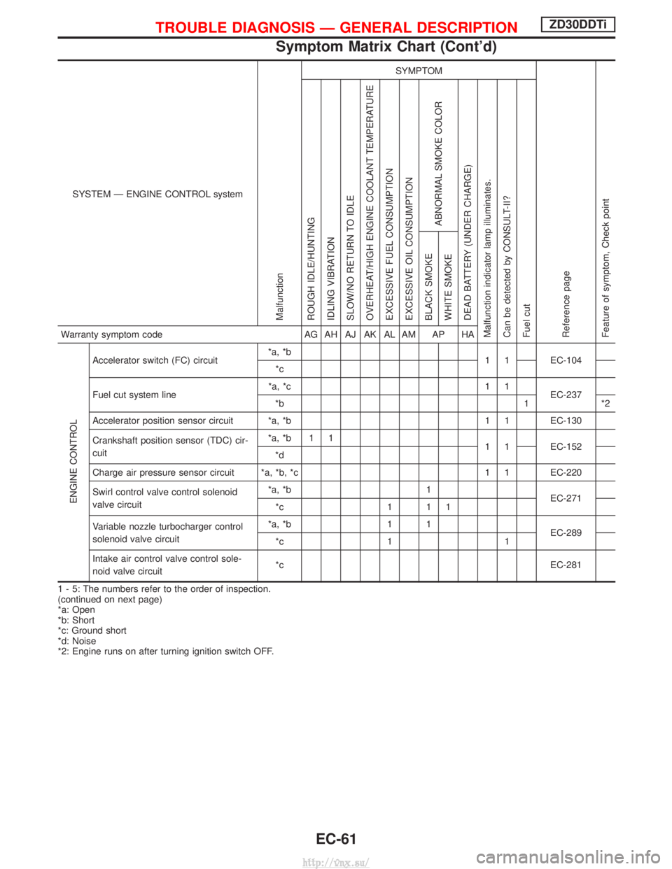
SYSTEM Ð ENGINE CONTROL system
Malfunction
SYMPTOM
Reference page
Feature of symptom, Check pointROUGH IDLE/HUNTING
IDLING VIBRATION
SLOW/NO RETURN TO IDLE
OVERHEAT/HIGH ENGINE COOLANT TEMPERATURE
EXCESSIVE FUEL CONSUMPTION
EXCESSIVE OIL CONSUMPTION
ABNORMAL SMOKE COLOR
DEAD BATTERY (UNDER CHARGE)
Malfunction indicator lamp illuminates.
Can be detected by CONSULT-II?
Fuel cut BLACK SMOKE
WHITE SMOKEWarranty symptom code
AG AH AJ AK AL AM AP HA
ENGINE CONTROL
Accelerator switch (FC) circuit*a, *b
1 1 EC-104
*c
Fuel cut system line *a, *c 1 1
EC-237
*b 1 *2
Accelerator position sensor circuit *a, *b 1 1 EC-130
Crankshaft position sensor (TDC) cir-
cuit *a, *b 1 1
1 1 EC-152
*d
Charge air pressure sensor circuit *a, *b, *c 1 1 EC-220
Swirl control valve control solenoid
valve circuit *a, *b 1
EC-271
*c 1 1 1
Variable nozzle turbocharger control
solenoid valve circuit *a, *b 1 1
EC-289
*c 1 1
Intake air control valve control sole-
noid valve circuit *c EC-281
1 - 5: The numbers refer to the order of inspection.
(continued on next page)
*a: Open
*b: Short
*c: Ground short
*d: Noise
*2: Engine runs on after turning ignition switch OFF.
TROUBLE DIAGNOSIS Ð GENERAL DESCRIPTIONZD30DDTi
Symptom Matrix Chart (Cont'd)
EC-61
http://vnx.su/
Page 348 of 1833
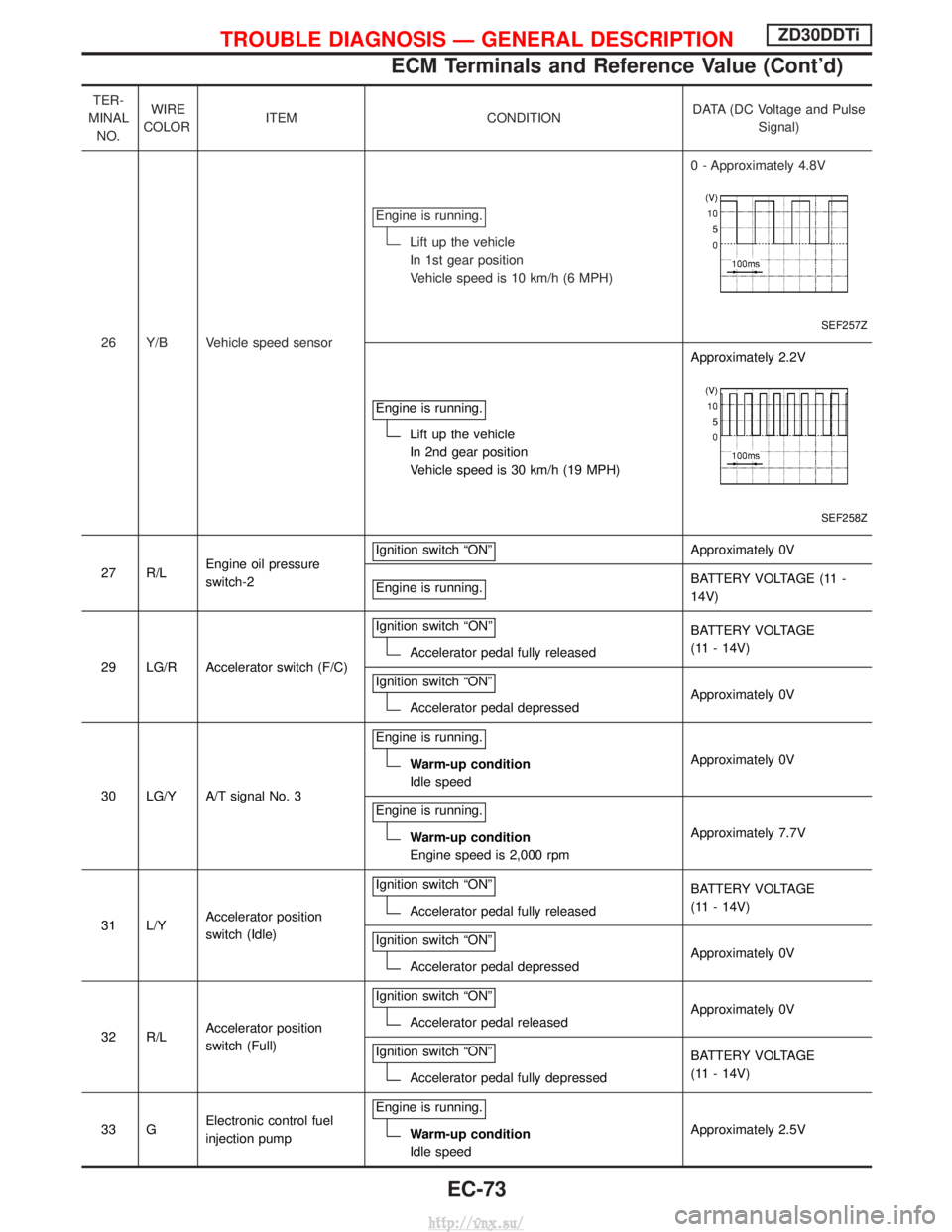
TER-
MINAL NO. WIRE
COLOR ITEM CONDITION DATA (DC Voltage and Pulse
Signal)
26 Y/B Vehicle speed sensor Engine is running.
Lift up the vehicle
In 1st gear position
Vehicle speed is 10 km/h (6 MPH)
0 - Approximately 4.8V
SEF257Z
Engine is running.
Lift up the vehicle
In 2nd gear position
Vehicle speed is 30 km/h (19 MPH)Approximately 2.2V
SEF258Z
27 R/L
Engine oil pressure
switch-2 Ignition switch ªONº
Approximately 0V
Engine is running.
BATTERY VOLTAGE (11 -
14V)
29 LG/R Accelerator switch (F/C) Ignition switch ªONº
Accelerator pedal fully released
BATTERY VOLTAGE
(11 - 14V)
Ignition switch ªONº
Accelerator pedal depressed Approximately 0V
30 LG/Y A/T signal No. 3 Engine is running.
Warm-up condition
Idle speed
Approximately 0V
Engine is running.
Warm-up condition
Engine speed is 2,000 rpm Approximately 7.7V
31 L/Y Accelerator position
switch (Idle) Ignition switch ªONº
Accelerator pedal fully released
BATTERY VOLTAGE
(11 - 14V)
Ignition switch ªONº
Accelerator pedal depressed Approximately 0V
32 R/L Accelerator position
switch (Full) Ignition switch ªONº
Accelerator pedal released
Approximately 0V
Ignition switch ªONº
Accelerator pedal fully depressed BATTERY VOLTAGE
(11 - 14V)
33 G Electronic control fuel
injection pump Engine is running.
Warm-up condition
Idle speed
Approximately 2.5V
TROUBLE DIAGNOSIS Ð GENERAL DESCRIPTIONZD30DDTi
ECM Terminals and Reference Value (Cont'd)
EC-73
http://vnx.su/
Page 350 of 1833
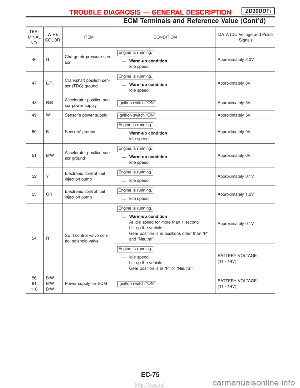
TER-
MINAL NO. WIRE
COLOR ITEM CONDITION DATA (DC Voltage and Pulse
Signal)
46 G Charge air pressure sen-
sor Engine is running.
Warm-up condition
Idle speed
Approximately 2.0V
47 L/R Crankshaft position sen-
sor (TDC) ground Engine is running.
Warm-up condition
Idle speed
Approximately 0V
48 R/B Accelerator position sen-
sor power supply Ignition switch ªONº
Approximately 5V
49 W Sensor's power supply Ignition switch ªONº
Approximately 5V
50 B Sensors' ground Engine is running.
Warm-up condition
Idle speed Approximately 0V
51 B/W Accelerator position sen-
sor ground Engine is running.
Warm-up condition
Idle speed
Approximately 0V
52 Y Electronic control fuel
injection pump Engine is running.
Idle speed
Approximately 0.1V
53 OR Electronic control fuel
injection pump Engine is running.
Idle speed
Approximately 1.0V
54 R Swirl control valve con-
trol solenoid valve Engine is running.
Warm-up condition
At idle speed for more than 1 second
Lift up the vehicle
Gear position is in positions other than ªPº
and ªNeutralº
Approximately 0.1V
Engine is running.
Idle speed
Lift up the vehicle
Gear position is in ªPº or ªNeutralº BATTERY VOLTAGE
(11 - 14V)
56
61
11 6 B/W
B/W
B/W
Power supply for ECM Ignition switch ªONº
BATTERY VOLTAGE
(11 - 14V)
TROUBLE DIAGNOSIS Ð GENERAL DESCRIPTIONZD30DDTi
ECM Terminals and Reference Value (Cont'd)
EC-75
http://vnx.su/
Page 386 of 1833
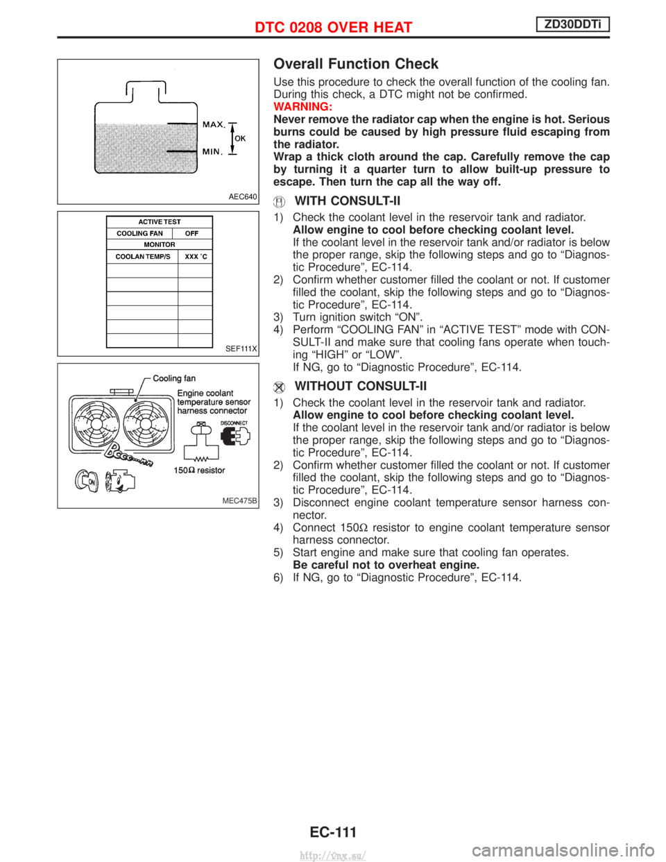
Overall Function Check
Use this procedure to check the overall function of the cooling fan.
During this check, a DTC might not be confirmed.
WARNING:
Never remove the radiator cap when the engine is hot. Serious
burns could be caused by high pressure fluid escaping from
the radiator.
Wrap a thick cloth around the cap. Carefully remove the cap
by turning it a quarter turn to allow built-up pressure to
escape. Then turn the cap all the way off.
WITH CONSULT-II
1) Check the coolant level in the reservoir tank and radiator.Allow engine to cool before checking coolant level.
If the coolant level in the reservoir tank and/or radiator is below
the proper range, skip the following steps and go to ªDiagnos-
tic Procedureº, EC-114.
2) Confirm whether customer filled the coolant or not. If customer filled the coolant, skip the following steps and go to ªDiagnos-
tic Procedureº, EC-114.
3) Turn ignition switch ªONº.
4) Perform ªCOOLING FANº in ªACTIVE TESTº mode with CON- SULT-II and make sure that cooling fans operate when touch-
ing ªHIGHº or ªLOWº.
If NG, go to ªDiagnostic Procedureº, EC-114.
WITHOUT CONSULT-II
1) Check the coolant level in the reservoir tank and radiator.Allow engine to cool before checking coolant level.
If the coolant level in the reservoir tank and/or radiator is below
the proper range, skip the following steps and go to ªDiagnos-
tic Procedureº, EC-114.
2) Confirm whether customer filled the coolant or not. If customer filled the coolant, skip the following steps and go to ªDiagnos-
tic Procedureº, EC-114.
3) Disconnect engine coolant temperature sensor harness con- nector.
4) Connect 150W resistor to engine coolant temperature sensor
harness connector.
5) Start engine and make sure that cooling fan operates. Be careful not to overheat engine.
6) If NG, go to ªDiagnostic Procedureº, EC-114.
AEC640
SEF111X
MEC475B
DTC 0208 OVER HEATZD30DDTi
EC-111
http://vnx.su/
Page 393 of 1833
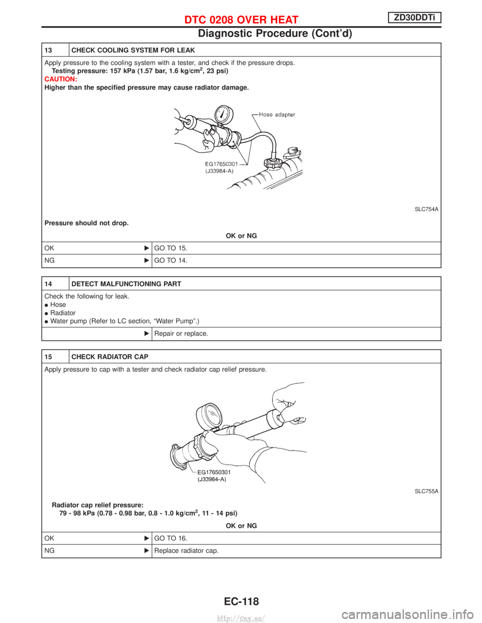
13 CHECK COOLING SYSTEM FOR LEAK
Apply pressure to the cooling system with a tester, and check if the pressure drops.Testing pressure: 157 kPa (1.57 bar, 1.6 kg/cm
2, 23 psi)
CAUTION:
Higher than the specified pressure may cause radiator damage.
SLC754A
Pressure should not drop.
OK or NG
OK EGO TO 15.
NG EGO TO 14.
14 DETECT MALFUNCTIONING PART
Check the following for leak.
IHose
I Radiator
I Water pump (Refer to LC section, ªWater Pumpº.)
ERepair or replace.
15 CHECK RADIATOR CAP
Apply pressure to cap with a tester and check radiator cap relief pressure.
SLC755A
Radiator cap relief pressure:
79 - 98 kPa (0.78 - 0.98 bar, 0.8 - 1.0 kg/cm2, 11 - 14 psi)
OK or NG
OK EGO TO 16.
NG EReplace radiator cap.
DTC 0208 OVER HEATZD30DDTi
Diagnostic Procedure (Cont'd)
EC-118
http://vnx.su/
Page 395 of 1833
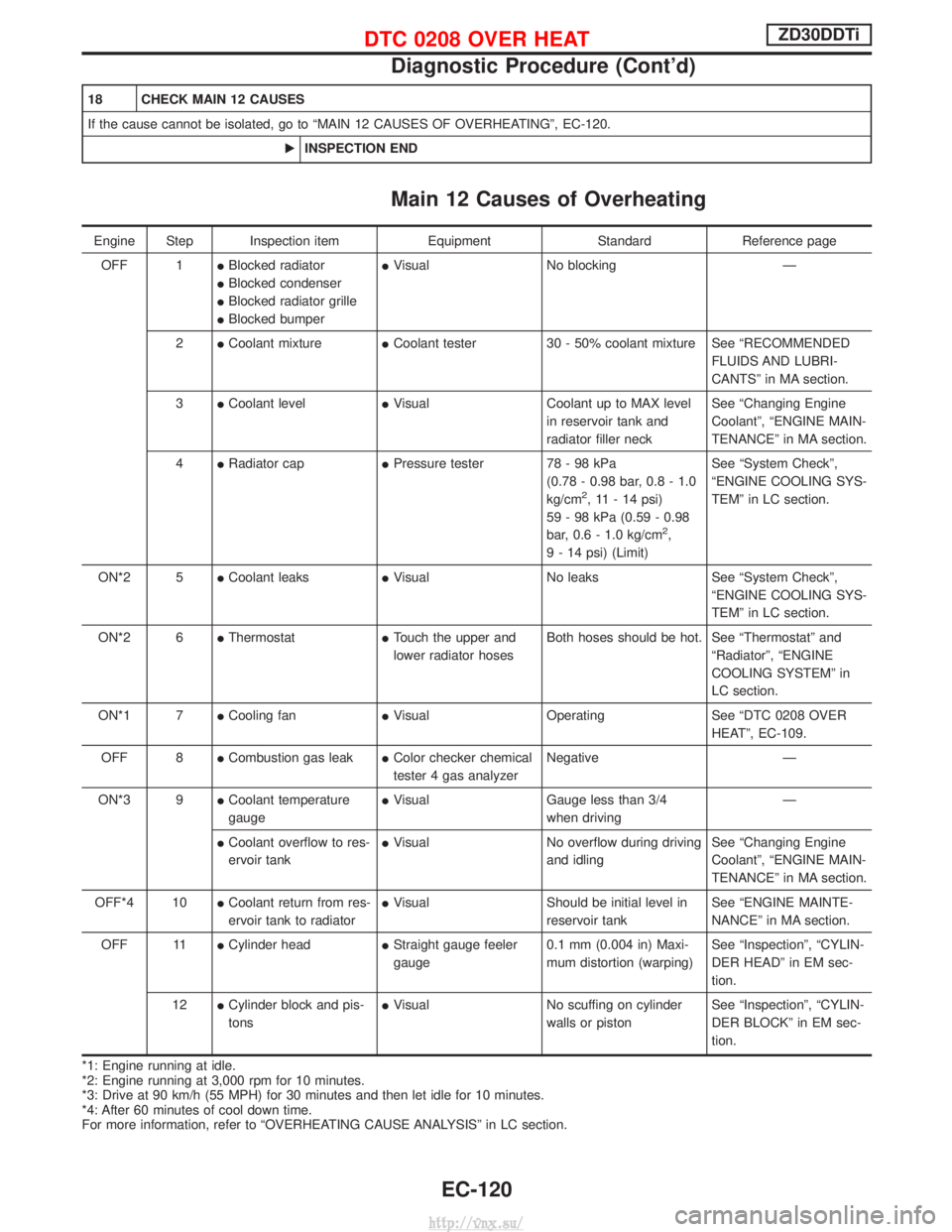
18 CHECK MAIN 12 CAUSES
If the cause cannot be isolated, go to ªMAIN 12 CAUSES OF OVERHEATINGº, EC-120.EINSPECTION END
Main 12 Causes of Overheating
Engine Step Inspection item EquipmentStandardReference page
OFF 1 IBlocked radiator
I Blocked condenser
I Blocked radiator grille
I Blocked bumper I
Visual No blocking Ð
2 ICoolant mixture ICoolant tester 30 - 50% coolant mixture See ªRECOMMENDED
FLUIDS AND LUBRI-
CANTSº in MA section.
3 ICoolant level IVisual Coolant up to MAX level
in reservoir tank and
radiator filler neck See ªChanging Engine
Coolantº, ªENGINE MAIN-
TENANCEº in MA section.
4 IRadiator cap IPressure tester 78 - 98 kPa
(0.78 - 0.98 bar, 0.8 - 1.0
kg/cm
2, 11 - 14 psi)
59 - 98 kPa (0.59 - 0.98
bar, 0.6 - 1.0 kg/cm
2,
9 - 14 psi) (Limit) See ªSystem Checkº,
ªENGINE COOLING SYS-
TEMº in LC section.
ON*2 5 ICoolant leaks IVisual No leaks See ªSystem Checkº,
ªENGINE COOLING SYS-
TEMº in LC section.
ON*2 6 IThermostat ITouch the upper and
lower radiator hoses Both hoses should be hot. See ªThermostatº and
ªRadiatorº, ªENGINE
COOLING SYSTEMº in
LC section.
ON*1 7 ICooling fan IVisual Operating See ªDTC 0208 OVER
HEATº, EC-109.
OFF 8 ICombustion gas leak IColor checker chemical
tester 4 gas analyzer Negative Ð
ON*3 9 ICoolant temperature
gauge I
Visual Gauge less than 3/4
when driving Ð
I Coolant overflow to res-
ervoir tank I
Visual No overflow during driving
and idling See ªChanging Engine
Coolantº, ªENGINE MAIN-
TENANCEº in MA section.
OFF*4 10 ICoolant return from res-
ervoir tank to radiator I
Visual Should be initial level in
reservoir tank See ªENGINE MAINTE-
NANCEº in MA section.
OFF 11 ICylinder head IStraight gauge feeler
gauge 0.1 mm (0.004 in) Maxi-
mum distortion (warping) See ªInspectionº, ªCYLIN-
DER HEADº in EM sec-
tion.
12 ICylinder block and pis-
tons I
Visual No scuffing on cylinder
walls or piston See ªInspectionº, ªCYLIN-
DER BLOCKº in EM sec-
tion.
*1: Engine running at idle.
*2: Engine running at 3,000 rpm for 10 minutes.
*3: Drive at 90 km/h (55 MPH) for 30 minutes and then let idle for 10 minutes.
*4: After 60 minutes of cool down time.
For more information, refer to ªOVERHEATING CAUSE ANALYSISº in LC section.
DTC 0208 OVER HEATZD30DDTi
Diagnostic Procedure (Cont'd)
EC-120
http://vnx.su/
Page 398 of 1833
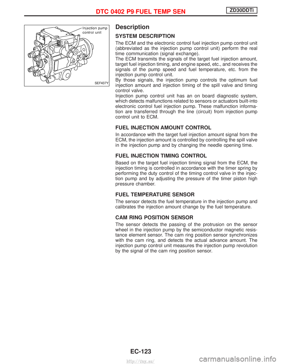
Description
SYSTEM DESCRIPTION
The ECM and the electronic control fuel injection pump control unit
(abbreviated as the injection pump control unit) perform the real
time communication (signal exchange).
The ECM transmits the signals of the target fuel injection amount,
target fuel injection timing, and engine speed, etc., and receives the
signals of the pump speed and fuel temperature, etc. from the
injection pump control unit.
By those signals, the injection pump controls the optimum fuel
injection amount and injection timing of the spill valve and timing
control valve.
Injection pump control unit has an on board diagnostic system,
which detects malfunctions related to sensors or actuators built-into
electronic control fuel injection pump. These malfunction informa-
tion are transferred through the line (circuit) from injection pump
control unit to ECM.
FUEL INJECTION AMOUNT CONTROL
In accordance with the target fuel injection amount signal from the
ECM, the injection amount is controlled by controlling the spill valve
in the injection pump and by changing the needle opening time.
FUEL INJECTION TIMING CONTROL
Based on the target fuel injection timing signal from the ECM, the
injection timing is controlled in accordance with the timer spring by
performing the duty control of the timing control valve in the injec-
tion pump and by adjusting the pressure of the timer piston high
pressure chamber.
FUEL TEMPERATURE SENSOR
The sensor detects the fuel temperature in the injection pump and
calibrates the injection amount change by the fuel temperature.
CAM RING POSITION SENSOR
The sensor detects the passing of the protrusion on the sensor
wheel in the injection pump by the semiconductor magnetic resis-
tance element sensor. The cam ring position sensor synchronizes
with the cam ring, and detects the actual advance amount. The
injection pump control unit measures the injection pump revolution
by the signal of the cam ring position sensor.
SEF437Y
DTC 0402 P9×FUEL TEMP SENZD30DDTi
EC-123
http://vnx.su/