2004 NISSAN TERRANO fuse diagram
[x] Cancel search: fuse diagramPage 1494 of 1833

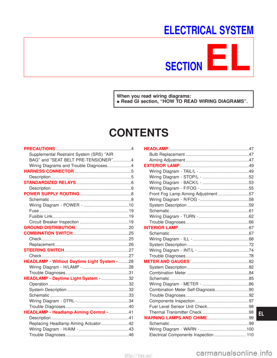
ELECTRICAL SYSTEMSECTION
EL
When you read wiring diagrams:
I Read GI section, ªHOW TO READ WIRING DIAGRAMSº.
CONTENTS
PRECAUTIONS ...............................................................4
Supplemental Restraint System (SRS) ²AIR
BAG² and²SEAT BELT PRE-TENSIONER² ...............4
Wiring Diagrams and Trouble Diagnoses....................4
HARNESS CONNECTOR ................................................5
Description ...................................................................5
STANDARDIZED RELAYS ..............................................6
Description ...................................................................6
POWER SUPPLY ROUTING ...........................................8
Schematic ....................................................................8
Wiring Diagram - POWER - ......................................10
Fuse ........................................................................\
...19
Fusible Link................................................................19
Circuit Breaker Inspection .........................................19
GROUND DISTRIBUTION .............................................20
COMBINATION SWITCH ...............................................25
Check ........................................................................\
.25
Replacement ..............................................................26
STEERING SWITCH ......................................................27
Check ........................................................................\
.27
HEADLAMP - Without Daytime Light System - .........28
Wiring Diagram - H/LAMP -.......................................28
Trouble Diagnoses.....................................................31
HEADLAMP - Daytime Light System - .......................32
Operation ...................................................................32
System Description ....................................................32
Schematic ..................................................................33
Wiring Diagram - DTRL - ...........................................34
Trouble Diagnoses.....................................................40
HEADLAMP - Headlamp Aiming Control - .................41
Description .................................................................41
Replacing Headlamp Aiming Actuator .......................42
Wiring Diagram - H/AIM - ..........................................43
Trouble Diagnoses.....................................................46 HEADLAMP
...................................................................47
Bulb Replacement .....................................................47
Aiming Adjustment .....................................................47
EXTERIOR LAMP ..........................................................49
Wiring Diagram - TAIL/L - ..........................................49
Wiring Diagram - STOP/L - .......................................52
Wiring Diagram - BACK/L - .......................................53
Wiring Diagram - F/FOG - .........................................55
Front Fog Lamp Aiming Adjustment ..........................57
Wiring Diagram - R/FOG -.........................................58
System Description ....................................................59
Schematic ..................................................................61
Wiring Diagram - TURN - ..........................................62
Trouble Diagnoses.....................................................66
INTERIOR LAMP ...........................................................67
Schematic ..................................................................67
Wiring Diagram - ILL - ...............................................68
System Description ....................................................72
Wiring Diagram - INT/L - ...........................................74
Trouble Diagnoses.....................................................78
METER AND GAUGES .................................................82
System Description ....................................................82
Combination Meter ....................................................84
Schematic ..................................................................85
Wiring Diagram - METER - .......................................86
Combination Meter Self-Diagnosis ............................90
Trouble Diagnoses.....................................................92
Components Inspection .............................................97
Fuel Level Sensor Unit Check...................................98
Thermal Transmitter Check .......................................98
WARNING LAMPS AND CHIME ...................................99
Schematic ..................................................................99
Wiring Diagram - WARN - .......................................100
Electrical Components Inspection ........................... 110
http://vnx.su/
Page 1726 of 1833

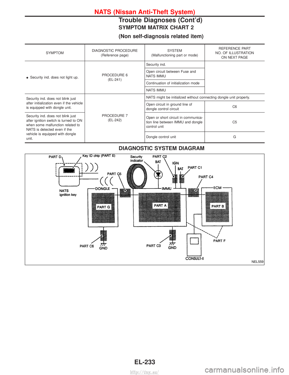
SYMPTOM MATRIX CHART 2
(Non self-diagnosis related item)
SYMPTOMDIAGNOSTIC PROCEDURE
(Reference page) SYSTEM
(Malfunctioning part or mode) REFERENCE PART
NO. OF ILLUSTRATION ON NEXT PAGE
I Security ind. does not light up. PROCEDURE 6
(EL-241) Security ind.
Open circuit between Fuse and
NATS IMMU
Continuation of initialization mode
NATS IMMU
Security ind. does not blink just
after initialization even if the vehicle
is equipped with dongle unit. PROCEDURE 7(EL-242) NATS might be initialized without connecting dongle unit properly.
Open circuit in ground line of
dongle control circuit
C6
Security ind. does not blink just
after ignition switch is turned to ON
when some malfunction related to
NATS is detected even if the
vehicle is equipped with dongle
unit. Open or short circuit in communica-
tion line between IMMU and dongle
control unit
C5
Dongle control unit G
DIAGNOSTIC SYSTEM DIAGRAM
NEL559
NATS (Nissan Anti-Theft System)
Trouble Diagnoses (Cont'd)
EL-233
http://vnx.su/
Page 1829 of 1833

F
Fan switch ......................................................HA-60
F/FOG - Wiring diagram .................................EL-55
Final drive disassembly............................PD-15, 37
Final drive pre-inspection .........................PD-15, 37
Final drive removal and installation ...............PD-15
Finisher, interior - See Trim ............................BT-18
Finisher, rear panel .........................................BT-18
Floor trim .........................................................BT-18
Fluid temperature sensor (A/T) .....................AT-146
Fluids .............................................MA-5, 17, 20, 36
Flywheel (clutch) .......................................CL-11, 12
Flywheel runout..............................................EM-94
Fog lamp, front .........................................EL-55, 57
Fog lamp, rear ................................................EL-58
Fork rod (M/T) ................................................MT-13
Forward clutch...............................................AT-162
Front axle ....................................................FA-4, 13
Front bumper ....................................................BT-6
Front case (Transfer) ..................................TF-9, 23
Front combination lamp removal andinstallation .....................................................BT-6
Front disc brake .............................................BR-27
Front door .......................................................BT-10
Front Door Trim...............................................BT-19
Front drive shaft (Transfer) .........................TF-9, 19
Front final drive disassembly (4WD) ..............PD-14
Front final drive removal and installa- tion (4WD) ............................................PD-12, 13
Front fog lamp ..........................................EL-55, 57
Front passenger air bag .................................RS-19
Front seat ........................................................BT-34
Front seat belt ..................................................RS-4
Front seat belt pre-tensioner ..........................RS-14
Front side air bag ...........................................RS-20
Front suspension ........................................FA-4, 29
Fuel cut control (at no load & high engine speed).....................................EC-22, 334
Fuel cut solenoid valve ................................EC-399
Fuel cut system ............................................EC-237
Fuel filler lid.......................................................BT-8
Fuel filter replacement...................MA-5, 20, 23, 33
Fuel gauge..................................FE-3, 6, EL-86, 98
Fuel injection system .............................EC-20, 329
Fuel injection timing feed back (Elec- tronic Fuel Injection Pump) ......................EC-197
Fuel precautions ................................................GI-6
Fuel pump and gauge ..............................FE-3, 6, 7
Fuel system ..................................................FE-3, 6
Fuel tank .......................................................FE-3, 6
Fuel temperature sensor ......................EC-123, 395
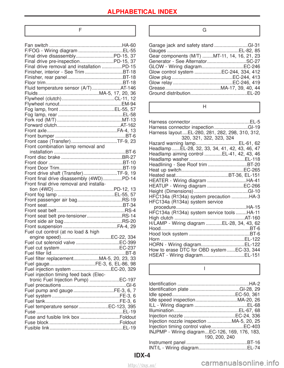
Fuse ................................................................EL-19
Fuse and fusible link box .............................Foldout
Fuse block ....................................................Foldout
Fusible link ......................................................EL-19 GGarage jack and safety stand .........................GI-31
Gauges .....................................................EL-82, 85
Gear components (M/T) ........MT-11, 14, 16, 21, 23
Generator - See Alternator .............................SC-27
GLOW - Wiring diagram...............................EC-246
Glow control system ....................EC-244, 334, 412
Glow plug .............................................EC-244, 413
Glow relay ............................................EC-246, 419
Grease .........................................MA-17, 39, 40, 44
Ground distribution..........................................EL-20
H
Harness connector ............................................EL-5
Harness connector inspection .........................GI-19
Harness layout ....EL-280, 281, 282, 298, 310, 312,320, 321, 322, 323, 324
Hazard warning lamp................................EL-61, 62
Headlamp ......EL-28, 32, 33, 34, 41, 42, 43, 46, 47
Headlamp aiming control .............EL-41, 42, 43, 46
Headlamp washer .........................................EL-118
Headlining - See Roof trim .............................BT-20
Heat up switch..............................................EC-265
Heated seat .......................................BT-36, EL-151
HEATER - Wiring diagram .............................HA-41
HEATUP - Wiring diagram ...........................EC-266
Height (Dimensions) ........................................GI-10
HFC134a (R134a) system precaution .............HA-3
HFC134a (R134a) system service procedure....................................................HA-15
HFC134a (R134a) system service tools ........HA-11
High clutch ....................................................AT-160
H/LAMP - Wiring diagram ............EL-28, 34, 43, 62
Hood..................................................................BT-6
Hood lock system .............................................BT-6
Horn ..............................................................EL-122
HORN - Wiring diagram................................EL-122
How to erase DTC for OBD system ......EC-33, 344
HSEAT - Wiring diagram...............................EL-151
I
Identification .....................................................HA-2
Identification plate .....................................GI-28, 29
Idle speed...............................................EC-50, 361
Idle speed inspection ...............................MA-20, 26
ILL - Wiring diagram .......................................EL-68
Illumination ................................................EL-67, 68
Injection nozzle ......................................EC-24, 336
Injection nozzle inspection ..................MA-5, 20, 25
Injection timing control valve ........................EC-403
INJPMP - Wiring diagram ...EC-126, 169, 176, 183, 190, 200, 240
Instrument panel .............................................BT-16
INT/L - Wiring diagram....................................EL-74
ALPHABETICAL INDEX
IDX-4
http://vnx.su/