2004 NISSAN TERRANO fuse diagram
[x] Cancel search: fuse diagramPage 657 of 1833
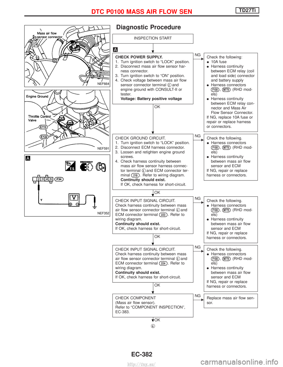
Diagnostic Procedure
INSPECTION START
CHECK POWER SUPPLY.
1. Turn ignition switch to ªLOCKº position.
2. Disconnect mass air flow sensor har- ness connector.
3. Turn ignition switch to ªONº position.
4. Check voltage between mass air flow sensor connector terminal q
2and
engine ground with CONSULT-II or
tester.
Voltage: Battery positive voltage
OK
ENG Check the following:
I10A fuse
I Harness continuity
between ECM relay (coil
and load side) connector
and battery supply
I Harness connectors
F100,M775(RHD mod-
els)
I Harness continuity
between ECM relay con-
nector and Mass Air
Flow Sensor Connector.
If NG, replace 10A fuse or
repair or replace harness
or connectors.
CHECK GROUND CIRCUIT.
1. Turn ignition switch to ªLOCKº position.
2. Disconnect ECM harness connector.
3. Loosen and retighten engine ground screws.
4. Check harness continuity between mass air flow sensor harness connec-
tor terminal q
3and ECM connector ter-
minal218. Refer to wiring diagram.
Continuity should exist.
If OK, check harness for short-circuit.
OK
ENG Check the following.
IHarness connectors
F100,M775(RHD mod-
els)
I Harness continuity
between mass air flow
sensor and ECM
If NG, repair or replace
harness or connectors.
CHECK INPUT SIGNAL CIRCUIT.
Check harness continuity between mass
air flow sensor connector terminal q
4and
ECM connector terminal223. Refer to
wiring diagram.
Continuity should exist.
If OK, check harness for short-circuit.
OK
ENG Check the following.
IHarness connectors
F100,M775(RHD mod-
els)
I Harness continuity
between mass air flow
sensor and ECM
If NG, repair or replace
harness or connectors.
CHECK INPUT SIGNAL CIRCUIT.
Check harness continuity between mass
air flow sensor connector terminal q
5and
ECM connector terminal224. Refer to
wiring diagram.
Continuity should exist.
If OK, check harness for short-circuit.
OK
ENG Check the following.
IHarness connectors
F100,M775(RHD mod-
els)
I Harness continuity
between mass air flow
sensor and ECM
If NG, repair or replace
harness or connectors.
CHECK COMPONENT
(Mass air flow sensor).
Refer to ªCOMPONENT INSPECTIONº,
EC-383.
OK
ENG Replace mass air flow sen-
sor.
qA
NEF664
NEF591
NEF352
H
H
H
H
H
H
DTC P0100 MASS AIR FLOW SENTD27Ti
EC-382
http://vnx.su/
Page 668 of 1833
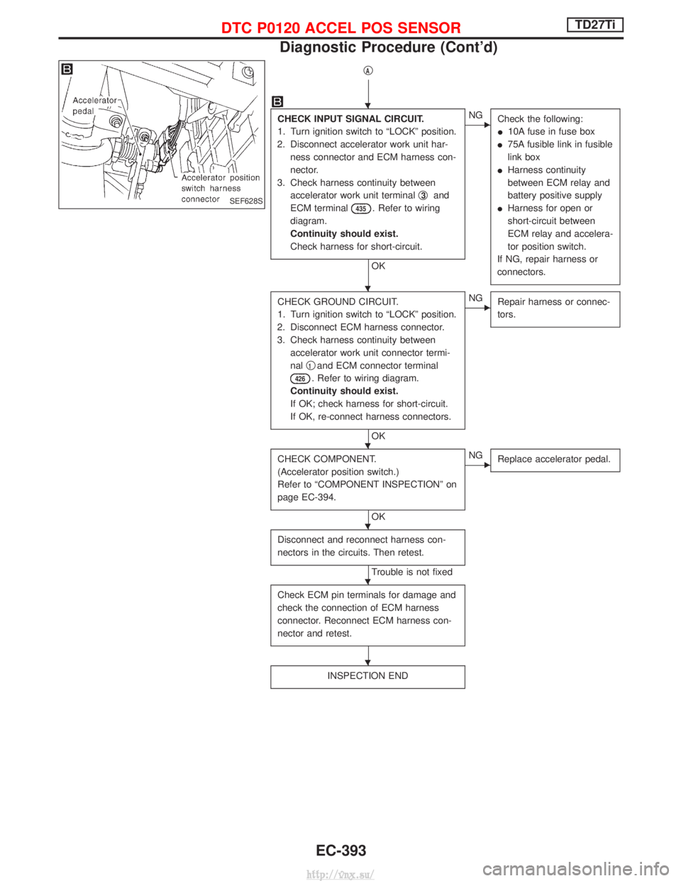
qA
CHECK INPUT SIGNAL CIRCUIT.
1. Turn ignition switch to ªLOCKº position.
2. Disconnect accelerator work unit har- ness connector and ECM harness con-
nector.
3. Check harness continuity between accelerator work unit terminal q
3and
ECM terminal
435. Refer to wiring
diagram.
Continuity should exist.
Check harness for short-circuit.
OK
ENG Check the following:
I10A fuse in fuse box
I 75A fusible link in fusible
link box
I Harness continuity
between ECM relay and
battery positive supply
I Harness for open or
short-circuit between
ECM relay and accelera-
tor position switch.
If NG, repair harness or
connectors.
CHECK GROUND CIRCUIT.
1. Turn ignition switch to ªLOCKº position.
2. Disconnect ECM harness connector.
3. Check harness continuity between accelerator work unit connector termi-
nal q
1and ECM connector terminal
426. Refer to wiring diagram.
Continuity should exist.
If OK; check harness for short-circuit.
If OK, re-connect harness connectors.
OK
ENG Repair harness or connec-
tors.
CHECK COMPONENT.
(Accelerator position switch.)
Refer to ªCOMPONENT INSPECTIONº on
page EC-394.
OK
ENGReplace accelerator pedal.
Disconnect and reconnect harness con-
nectors in the circuits. Then retest.
Trouble is not fixed
Check ECM pin terminals for damage and
check the connection of ECM harness
connector. Reconnect ECM harness con-
nector and retest.
INSPECTION END
SEF628S
H
H
H
H
H
H
DTC P0120 ACCEL POS SENSORTD27Ti
Diagnostic Procedure (Cont'd)
EC-393
http://vnx.su/
Page 681 of 1833
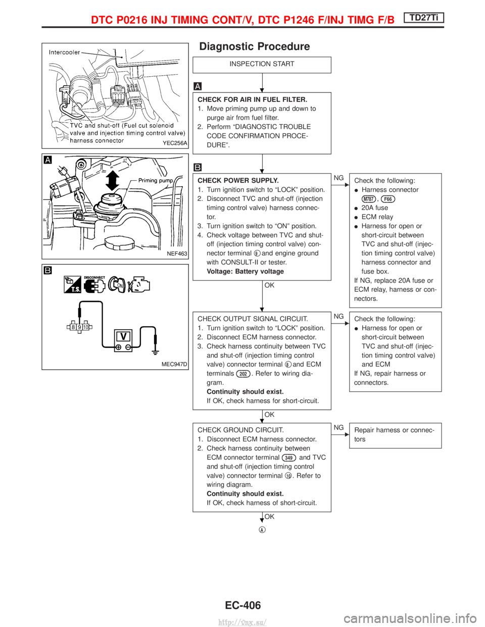
Diagnostic Procedure
INSPECTION START
CHECK FOR AIR IN FUEL FILTER.
1. Move priming pump up and down topurge air from fuel filter.
2. Perform ªDIAGNOSTIC TROUBLE CODE CONFIRMATION PROCE-
DUREº.
CHECK POWER SUPPLY.
1. Turn ignition switch to ªLOCKº position.
2. Disconnect TVC and shut-off (injection timing control valve) harness connec-
tor.
3. Turn ignition switch to ªONº position.
4. Check voltage between TVC and shut- off (injection timing control valve) con-
nector terminal q
9and engine ground
with CONSULT-II or tester.
Voltage: Battery voltage
OK
ENG Check the following:
IHarness connector
M787,F66
I20A fuse
I ECM relay
I Harness for open or
short-circuit between
TVC and shut-off (injec-
tion timing control valve)
harness connector and
fuse box.
If NG, replace 20A fuse or
ECM relay, harness or con-
nectors.
CHECK OUTPUT SIGNAL CIRCUIT.
1. Turn ignition switch to ªLOCKº position.
2. Disconnect ECM harness connector.
3. Check harness continuity between TVC and shut-off (injection timing control
valve) connector terminal q
8and ECM
terminals
202. Refer to wiring dia-
gram.
Continuity should exist.
If OK, check harness for short-circuit.
OK
ENG Check the following:
IHarness for open or
short-circuit between
TVC and shut-off (injec-
tion timing control valve)
and ECM
If NG, repair harness or
connectors.
CHECK GROUND CIRCUIT.
1. Disconnect ECM harness connector.
2. Check harness continuity between ECM connector terminal
349and TVC
and shut-off (injection timing control
valve) connector terminal q
10. Refer to
wiring diagram.
Continuity should exist.
If OK, check harness of short-circuit.
OK
ENG Repair harness or connec-
tors
qA
YEC256A
NEF463
MEC947D
H
H
H
H
H
DTC P0216 INJ TIMING CONT/V, DTC P1246 F/INJ TIMG F/BTD27Ti
EC-406
http://vnx.su/
Page 691 of 1833
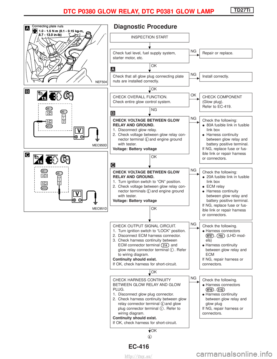
Diagnostic Procedure
INSPECTION START
Check fuel level, fuel supply system,
starter motor, etc.
OK
ENGRepair or replace.
Check that all glow plug connecting plate
nuts are installed correctly.
OK
ENGInstall correctly.
CHECK OVERALL FUNCTION.
Check entire glow control system.
NG
EOKCHECK COMPONENT
(Glow plug).
Refer to EC-419.
CHECK VOLTAGE BETWEEN GLOW
RELAY AND GROUND.
1. Disconnect glow relay.
2. Check voltage between glow relay con- nector terminal q
5and engine ground
with tester.
Voltage: Battery voltage
OK
ENG Check the following:
I80A fusible link in fusible
link box
I Harness continuity
between glow relay and
battery positive terminal.
If NG, replace fuse or fus-
ible link or repair harness
or connectors.
CHECK VOLTAGE BETWEEN GLOW
RELAY AND GROUND.
1. Turn ignition switch to ªONº position.
2. Check voltage between glow relay con- nector terminals q
2and engine ground
with tester.
Voltage: Battery voltage
OK
ENG Check the following:
I20A fusible link in fusible
link box
I ECM relay
I Harness continuity
between glow relay and
battery positive terminal.
If NG, replace fuse or fus-
ible link or repair harness
or connectors.
CHECK OUTPUT SIGNAL CIRCUIT.
1. Turn ignition switch to ªLOCKº position.
2. Disconnect ECM harness connector.
3. Check harness continuity between ECM connector terminal
214and
glow relay connector terminal q
1. Refer
to wiring diagram.
Continuity should exist.
If OK, check harness for short-circuit.
OK
ENG Check the following.
IHarness connectors
M787,F66(LHD mod-
els)
I Harness continuity
between glow relay and
ECM
If NG, repair harness or
connectors.
CHECK HARNESS CONTINUITY
BETWEEN GLOW RELAY AND GLOW
PLUG.
1. Disconnect glow plug connector.
2. Check harness continuity between glow relay connector terminal q
3and glow
plug connector terminal q
1. Refer to
wiring diagram.
Continuity should exist.
If OK, check harness for short-circuit.
OK
ENG Check the following.
IHarness connectors
M740,E142
IHarness continuity
between glow relay and
glow plug
If NG, repair harness or
connectors.
qA
NEF504
MEC950D
MEC951D
H
H
H
H
H
H
H
H
DTC P0380 GLOW RELAY, DTC P0381 GLOW LAMPTD27Ti
EC-416
http://vnx.su/
Page 692 of 1833
qA
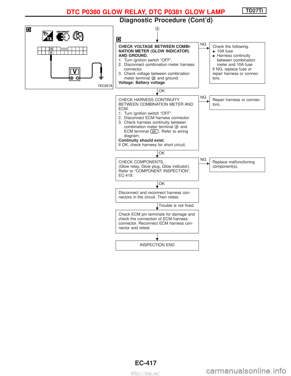
CHECK VOLTAGE BETWEEN COMBI-
NATION METER (GLOW INDICATOR)
AND GROUND.
1. Turn ignition switch ªOFFº.
2. Disconnect combination meter harness connector.
3. Check voltage between combination meter terminal q
28and ground.
Voltage: Battery voltage
OK
ENG Check the following.
I10A fuse
I Harness continuity
between combination
meter and 10A fuse
If NG, replace fuse or
repair harness or connec-
tors.
CHECK HARNESS CONTINUITY
BETWEEN COMBINATION METER AND
ECM.
1. Turn ignition switch ªOFFº.
2. Disconnect ECM harness connector.
3. Check harness continuity between combination meter terminal q
47and
ECM terminal221. Refer to wiring
diagram.
Continuity should exist.
If OK, check harness for short circuit.
OK
ENG Repair harness or connec-
tors.
CHECK COMPONENTS.
(Glow relay, Glow plug, Glow indicator).
Refer to ªCOMPONENT INSPECTIONº,
EC-419.
OK
ENGReplace malfunctioning
component(s).
Disconnect and reconnect harness con-
nectors in the circuit. Then retest.
Trouble is not fixed.
Check ECM pin terminals for damage and
check the connection of ECM harness
connector. Reconnect ECM harness con-
nector and retest.
INSPECTION END
YEC257A
H
H
H
H
H
H
DTC P0380 GLOW RELAY, DTC P0381 GLOW LAMPTD27Ti
Diagnostic Procedure (Cont'd)
EC-417
http://vnx.su/
Page 700 of 1833
Diagnostic Procedure
INSPECTION START
(Stop lamp switch circuit)
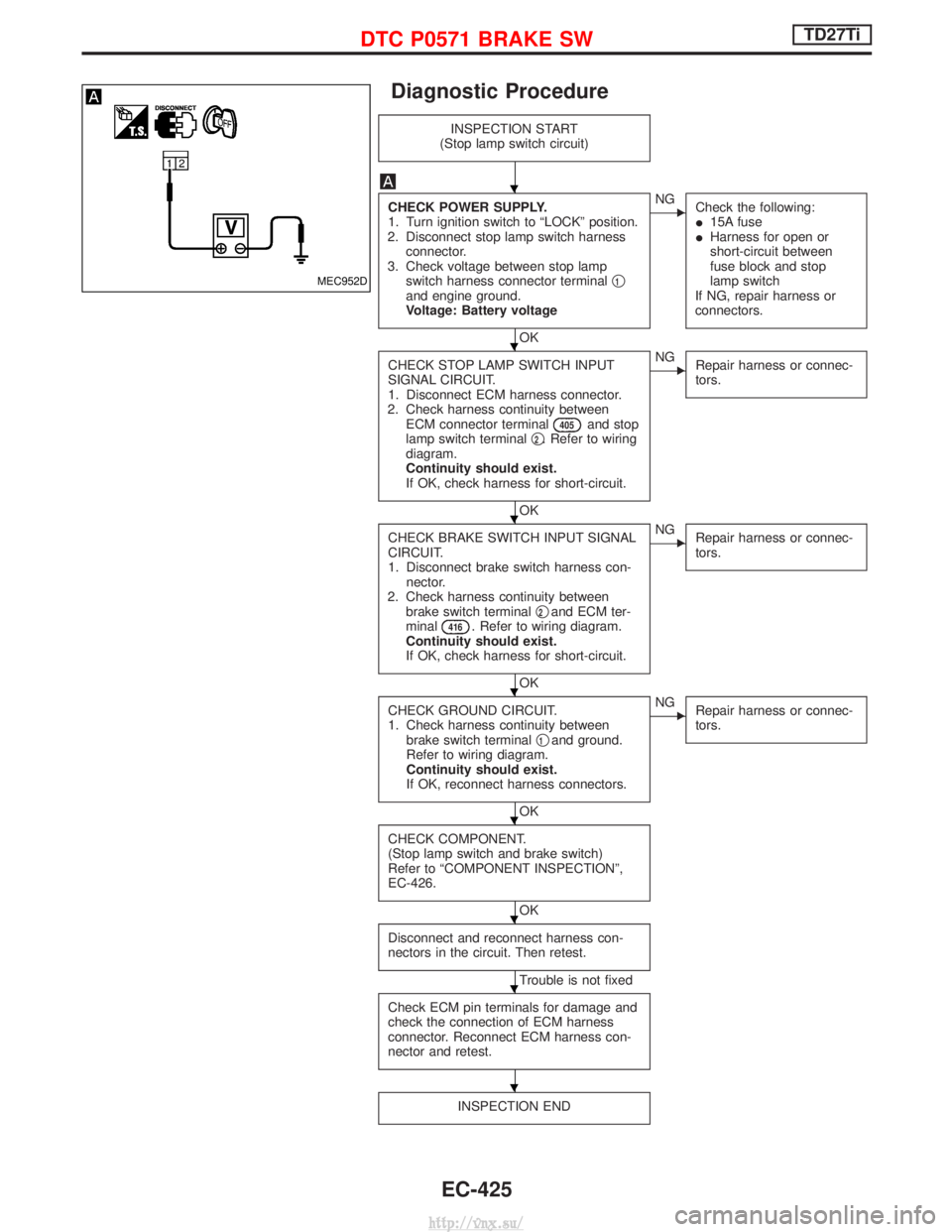
CHECK POWER SUPPLY.
1. Turn ignition switch to ªLOCKº position.
2. Disconnect stop lamp switch harness connector.
3. Check voltage between stop lamp switch harness connector terminal q
1and engine ground.
Voltage: Battery voltage
OK
ENG
Check the following:
I15A fuse
I Harness for open or
short-circuit between
fuse block and stop
lamp switch
If NG, repair harness or
connectors.
CHECK STOP LAMP SWITCH INPUT
SIGNAL CIRCUIT.
1. Disconnect ECM harness connector.
2. Check harness continuity between ECM connector terminal
405and stop
lamp switch terminal q2. Refer to wiring
diagram.
Continuity should exist.
If OK, check harness for short-circuit.
OK
ENG Repair harness or connec-
tors.
CHECK BRAKE SWITCH INPUT SIGNAL
CIRCUIT.
1. Disconnect brake switch harness con-
nector.
2. Check harness continuity between brake switch terminal q
2and ECM ter-
minal416. Refer to wiring diagram.
Continuity should exist.
If OK, check harness for short-circuit.
OK
ENG Repair harness or connec-
tors.
CHECK GROUND CIRCUIT.
1. Check harness continuity between
brake switch terminal q
1and ground.
Refer to wiring diagram.
Continuity should exist.
If OK, reconnect harness connectors.
OK
ENG Repair harness or connec-
tors.
CHECK COMPONENT.
(Stop lamp switch and brake switch)
Refer to ªCOMPONENT INSPECTIONº,
EC-426.
OK
Disconnect and reconnect harness con-
nectors in the circuit. Then retest.
Trouble is not fixed
Check ECM pin terminals for damage and
check the connection of ECM harness
connector. Reconnect ECM harness con-
nector and retest.
INSPECTION END
MEC952D
H
H
H
H
H
H
H
H
DTC P0571 BRAKE SWTD27Ti
EC-425
http://vnx.su/
Page 704 of 1833
Diagnostic Procedure
INSPECTION START
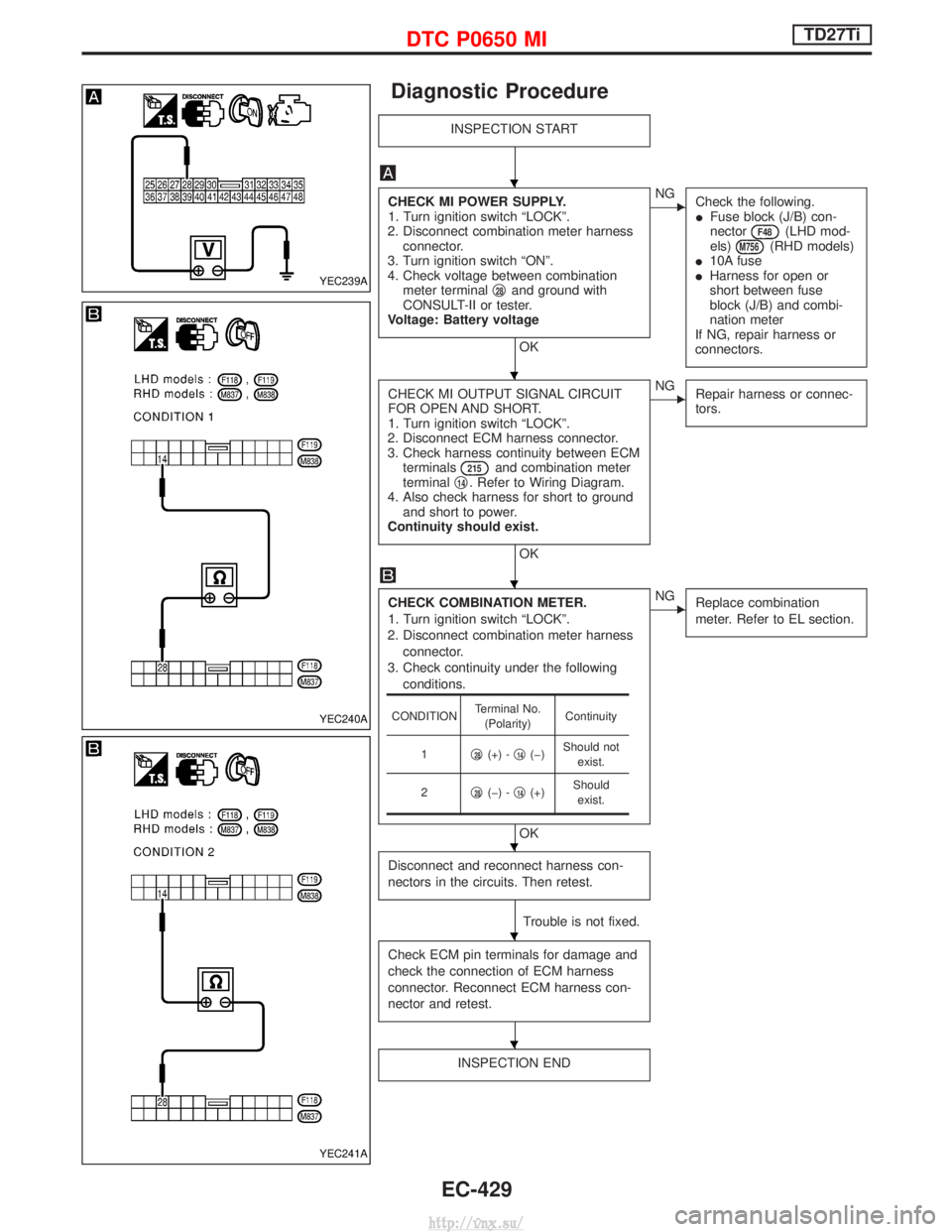
CHECK MI POWER SUPPLY.
1. Turn ignition switch ªLOCKº.
2. Disconnect combination meter harness connector.
3. Turn ignition switch ªONº.
4. Check voltage between combination meter terminal q
28and ground with
CONSULT-II or tester.
Voltage: Battery voltage
OK
ENG Check the following.
IFuse block (J/B) con-
nector
F48(LHD mod-
els)M756(RHD models)
I 10A fuse
I Harness for open or
short between fuse
block (J/B) and combi-
nation meter
If NG, repair harness or
connectors.
CHECK MI OUTPUT SIGNAL CIRCUIT
FOR OPEN AND SHORT.
1. Turn ignition switch ªLOCKº.
2. Disconnect ECM harness connector.
3. Check harness continuity between ECM terminals
215and combination meter
terminal q14. Refer to Wiring Diagram.
4. Also check harness for short to ground and short to power.
Continuity should exist.
OK
ENG Repair harness or connec-
tors.
CHECK COMBINATION METER.
1. Turn ignition switch ªLOCKº.
2. Disconnect combination meter harness connector.
3. Check continuity under the following conditions.
OK
ENG Replace combination
meter. Refer to EL section.
Disconnect and reconnect harness con-
nectors in the circuits. Then retest.
Trouble is not fixed.
Check ECM pin terminals for damage and
check the connection of ECM harness
connector. Reconnect ECM harness con-
nector and retest.
INSPECTION END
CONDITION Terminal No.
(Polarity) Continuity
1 q
28(+) -q14(þ) Should not
exist.
2 q
28(þ) -q14(+) Should
exist.
YEC239A
YEC240A
YEC241A
H
H
H
H
H
H
DTC P0650 MITD27Ti
EC-429
http://vnx.su/
Page 719 of 1833
Diagnostic Procedure
INSPECTION START
CHECK OVERALL FUNCTION.
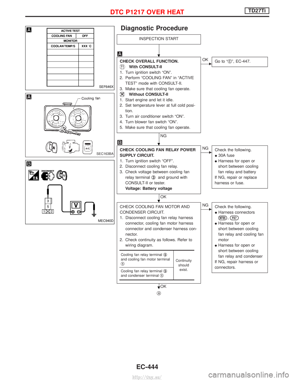
With CONSULT-II
1. Turn ignition switch ªONº.
2. Perform ªCOOLING FANº in ªACTIVE TESTº mode with CONSULT-II.
3. Make sure that cooling fan operate.
Without CONSULT-II
1. Start engine and let it idle.
2. Set temperature lever at full cold posi- tion.
3. Turn air conditioner switch ªONº.
4. Turn blower fan switch ªONº.
5. Make sure that cooling fan operate.
NG
EOK Go to ª qCº, EC-447.
CHECK COOLING FAN RELAY POWER
SUPPLY CIRCUIT.
1. Turn ignition switch ªOFFº.
2. Disconnect cooling fan relay.
3. Check voltage between cooling fan relay terminal q
3and ground with
CONSULT-II or tester.
Voltage: Battery voltage
OK
ENG Check the following.
I30A fuse
I Harness for open or
short between cooling
fan relay and battery
If NG, repair or replace
harness or fuse.
CHECK COOLING FAN MOTOR AND
CONDENSER CIRCUIT.
1. Disconnect cooling fan relay harness connector, cooling fan motor harness
connector and condenser harness con-
nector.
2. Check continuity as follows. Refer to wiring diagram.
OK
ENG Check the following.
IHarness connectors
M785,F67
IHarness for open or
short between cooling
fan relay and cooling fan
motor
I Harness for open or
short between cooling
fan relay and condenser
If NG, repair harness or
connectors.
qA
Cooling fan relay terminal q5and cooling fan motor terminal
q1Continuity
shouldexist.
Cooling fan relay terminal q
5and condenser terminalq1
SEF646X
SEC163BA
MEC940D
H
H
H
H
DTC P1217 OVER HEATTD27Ti
EC-444
http://vnx.su/