2004 NISSAN TERRANO glow plug
[x] Cancel search: glow plugPage 694 of 1833

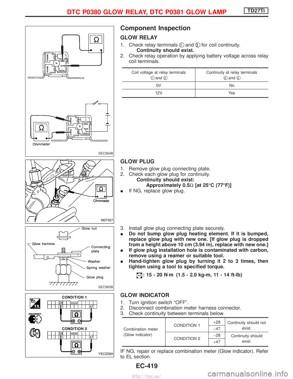
Component Inspection
GLOW RELAY
1. Check relay terminalsq1andq2for coil continuity.
Continuity should exist.
2. Check relay operation by applying battery voltage across relay coil terminals.
Coil voltage at relay terminals
q
1andq2
Continuity at relay terminals
q
5andq3
0V
No
12V Yes
GLOW PLUG
1. Remove glow plug connecting plate.
2. Check each glow plug for continuity.
Continuity should exist:Approximately 0.5W [at 25ÉC (77ÉF)]
I If NG, replace glow plug.
3. Install glow plug connecting plate securely.
I Do not bump glow plug heating element. If it is bumped,
replace glow plug with new one. [If glow plug is dropped
from a height above 10 cm (3.94 in), replace with new one.]
I If glow plug installation hole is contaminated with carbon,
remove using a reamer or suitable tool.
I Hand-tighten glow plug by turning it 2 to 3 times, then
tighten using a tool to specified torque.
:15-20N ×m (1.5 - 2.0 kg-m, 11 - 14 ft-lb)
GLOW INDICATOR
1. Turn ignition switch ªOFFº.
2. Disconnect combination meter harness connector.
3. Check continuity between terminals below.
Combination meter
(Glow indicator) CONDITION 1
+28
Continuity should not
exist.
þ47
CONDITION 2 þ28
Continuity should
exist.
+47
IF NG, repair or replace combination meter (Glow indicator). Refer
to EL section.
SEC564B
NEF507
SEC565B
YEC258A
DTC P0380 GLOW RELAY, DTC P0381 GLOW LAMPTD27Ti
EC-419
http://vnx.su/
Page 751 of 1833

General Specifications
Engine speed
Unit: rpm
EngineTD27Ti
Idle speed A/C: ON 725
845
Maximum engine speed 5,500
Pump numbers
Engine Part numberPump assembly num-
ber
TD27Ti 16700 7F406 A 460 801 135
Pump data is not yet available.
Refer to CALIBRATION STANDARD published
by BOSCH.
Injection Nozzle
INSPECTION AND ADJUSTMENT
Injection nozzle assembly
Unit: kPa (bar, kg/cm2, psi)
Initial injection pressure
New 12,749 - 13,730 (127.5 - 137.3, 130 - 140,
1,849 - 1,991)
Used 12,259 - 12,749 (122.6 - 127.5, 120 - 135,
1,706 - 1,849)
Inspection and Adjustment
Plunger lift mm (in)
at TDC 0.275 0.02
(0.0108) (0.0008)
Idle speed rpm
(ªNº or ªPº position) 725 25
MASS AIR FLOW SENSOR
Supply voltage
V Approximately 5
Output voltage V1.5 - 2.7*
*: Engine is warmed up sufficiently and idling under no-load.
ENGINE COOLANT TEMPERATURE
SENSOR
Temperature ÉC (ÉF) Resistance kW
20 (68) 2.1 - 2.9
50 (122) 0.68 - 1.00
90 (194) 0.236 - 0.260
CONTROL SLEEVE POSITION SENSOR
Resistance [at 25ÉC (77ÉF)] WApproximately 6.1
INJECTION TIMING CONTROL VALVE
Resistance [at 25ÉC (77ÉF)] WApproximately 15
NEEDLE LIFT SENSOR
Resistance [at 25ÉC (77ÉF)] WApproximately 105
CRANKSHAFT POSITION SENSOR (TDC)
Resistance [at 25ÉC (77ÉF)] WApproximately 900
GLOW PLUG
Resistance [at 25ÉC (77ÉF)] W0.5
ACCELERATOR POSITION SENSOR
Throttle valve conditions Resistance kW
[at 25ÉC (77ÉF)]
Completely closed Approximately 1.2
Partially open 1.2 - 1.9
Completely open Approximately 1.9
FUEL TEMPERATURE SENSOR
Temperature ÉC (ÉF)Resistance kW
25 (77) Approximately 1.9
SERVICE DATA AND SPECIFICATIONS (SDS)TD27Ti
EC-476
http://vnx.su/
Page 1829 of 1833

F
Fan switch ......................................................HA-60
F/FOG - Wiring diagram .................................EL-55
Final drive disassembly............................PD-15, 37
Final drive pre-inspection .........................PD-15, 37
Final drive removal and installation ...............PD-15
Finisher, interior - See Trim ............................BT-18
Finisher, rear panel .........................................BT-18
Floor trim .........................................................BT-18
Fluid temperature sensor (A/T) .....................AT-146
Fluids .............................................MA-5, 17, 20, 36
Flywheel (clutch) .......................................CL-11, 12
Flywheel runout..............................................EM-94
Fog lamp, front .........................................EL-55, 57
Fog lamp, rear ................................................EL-58
Fork rod (M/T) ................................................MT-13
Forward clutch...............................................AT-162
Front axle ....................................................FA-4, 13
Front bumper ....................................................BT-6
Front case (Transfer) ..................................TF-9, 23
Front combination lamp removal andinstallation .....................................................BT-6
Front disc brake .............................................BR-27
Front door .......................................................BT-10
Front Door Trim...............................................BT-19
Front drive shaft (Transfer) .........................TF-9, 19
Front final drive disassembly (4WD) ..............PD-14
Front final drive removal and installa- tion (4WD) ............................................PD-12, 13
Front fog lamp ..........................................EL-55, 57
Front passenger air bag .................................RS-19
Front seat ........................................................BT-34
Front seat belt ..................................................RS-4
Front seat belt pre-tensioner ..........................RS-14
Front side air bag ...........................................RS-20
Front suspension ........................................FA-4, 29
Fuel cut control (at no load & high engine speed).....................................EC-22, 334
Fuel cut solenoid valve ................................EC-399
Fuel cut system ............................................EC-237
Fuel filler lid.......................................................BT-8
Fuel filter replacement...................MA-5, 20, 23, 33
Fuel gauge..................................FE-3, 6, EL-86, 98
Fuel injection system .............................EC-20, 329
Fuel injection timing feed back (Elec- tronic Fuel Injection Pump) ......................EC-197
Fuel precautions ................................................GI-6
Fuel pump and gauge ..............................FE-3, 6, 7
Fuel system ..................................................FE-3, 6
Fuel tank .......................................................FE-3, 6
Fuel temperature sensor ......................EC-123, 395
Fuse ................................................................EL-19
Fuse and fusible link box .............................Foldout
Fuse block ....................................................Foldout
Fusible link ......................................................EL-19 GGarage jack and safety stand .........................GI-31
Gauges .....................................................EL-82, 85
Gear components (M/T) ........MT-11, 14, 16, 21, 23
Generator - See Alternator .............................SC-27
GLOW - Wiring diagram...............................EC-246
Glow control system ....................EC-244, 334, 412
Glow plug .............................................EC-244, 413
Glow relay ............................................EC-246, 419
Grease .........................................MA-17, 39, 40, 44
Ground distribution..........................................EL-20
H
Harness connector ............................................EL-5
Harness connector inspection .........................GI-19
Harness layout ....EL-280, 281, 282, 298, 310, 312,320, 321, 322, 323, 324
Hazard warning lamp................................EL-61, 62
Headlamp ......EL-28, 32, 33, 34, 41, 42, 43, 46, 47
Headlamp aiming control .............EL-41, 42, 43, 46
Headlamp washer .........................................EL-118
Headlining - See Roof trim .............................BT-20
Heat up switch..............................................EC-265
Heated seat .......................................BT-36, EL-151
HEATER - Wiring diagram .............................HA-41
HEATUP - Wiring diagram ...........................EC-266
Height (Dimensions) ........................................GI-10
HFC134a (R134a) system precaution .............HA-3
HFC134a (R134a) system service procedure....................................................HA-15
HFC134a (R134a) system service tools ........HA-11
High clutch ....................................................AT-160
H/LAMP - Wiring diagram ............EL-28, 34, 43, 62
Hood..................................................................BT-6
Hood lock system .............................................BT-6
Horn ..............................................................EL-122
HORN - Wiring diagram................................EL-122
How to erase DTC for OBD system ......EC-33, 344
HSEAT - Wiring diagram...............................EL-151
I
Identification .....................................................HA-2
Identification plate .....................................GI-28, 29
Idle speed...............................................EC-50, 361
Idle speed inspection ...............................MA-20, 26
ILL - Wiring diagram .......................................EL-68
Illumination ................................................EL-67, 68
Injection nozzle ......................................EC-24, 336
Injection nozzle inspection ..................MA-5, 20, 25
Injection timing control valve ........................EC-403
INJPMP - Wiring diagram ...EC-126, 169, 176, 183, 190, 200, 240
Instrument panel .............................................BT-16
INT/L - Wiring diagram....................................EL-74
ALPHABETICAL INDEX
IDX-4
http://vnx.su/