2004 NISSAN TERRANO glow plug
[x] Cancel search: glow plugPage 195 of 1833
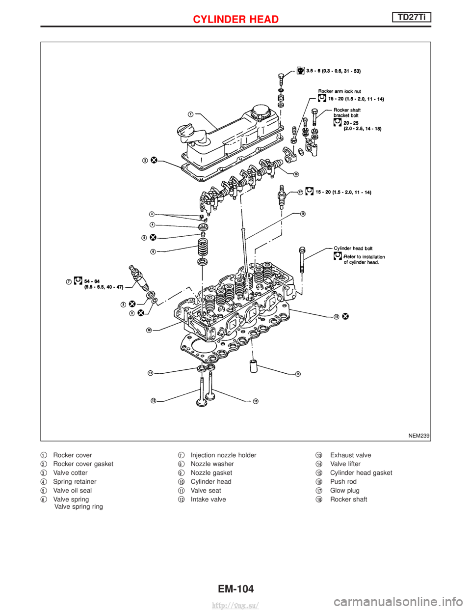
q1Rocker cover
q
2Rocker cover gasket
q
3Valve cotter
q
4Spring retainer
q
5Valve oil seal
q
6Valve spring Valve spring ring q
7Injection nozzle holder
q
8Nozzle washer
q
9Nozzle gasket
q
10Cylinder head
q
11Valve seat
q
12Intake valve q
13Exhaust valve
q
14Valve lifter
q
15Cylinder head gasket
q
16Push rod
q
17Glow plug
q
18Rocker shaft
NEM239
CYLINDER HEADTD27Ti
EM-104
http://vnx.su/
Page 197 of 1833
Disassembly
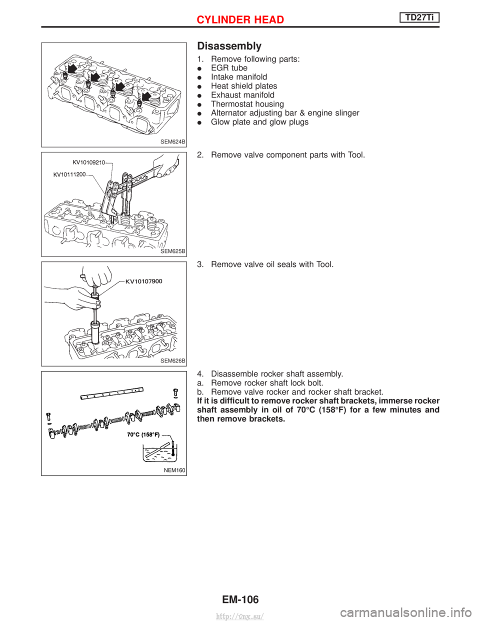
1. Remove following parts:
IEGR tube
I Intake manifold
I Heat shield plates
I Exhaust manifold
I Thermostat housing
I Alternator adjusting bar & engine slinger
I Glow plate and glow plugs
2. Remove valve component parts with Tool.
3. Remove valve oil seals with Tool.
4. Disassemble rocker shaft assembly.
a. Remove rocker shaft lock bolt.
b. Remove valve rocker and rocker shaft bracket.
If it is difficult to remove rocker shaft brackets, immerse rocker
shaft assembly in oil of 70ÉC (158ÉF) for a few minutes and
then remove brackets.
SEM624B
SEM625B
SEM626B
NEM160
CYLINDER HEADTD27Ti
EM-106
http://vnx.su/
Page 207 of 1833
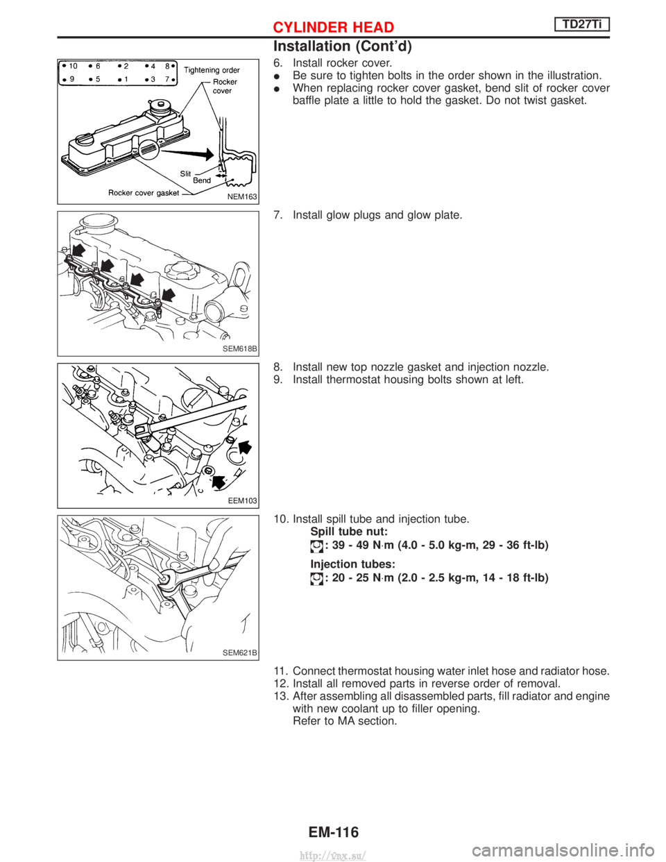
6. Install rocker cover.
IBe sure to tighten bolts in the order shown in the illustration.
I When replacing rocker cover gasket, bend slit of rocker cover
baffle plate a little to hold the gasket. Do not twist gasket.
7. Install glow plugs and glow plate.
8. Install new top nozzle gasket and injection nozzle.
9. Install thermostat housing bolts shown at left.
10. Install spill tube and injection tube. Spill tube nut:
:39-49N ×m (4.0 - 5.0 kg-m, 29 - 36 ft-lb)
Injection tubes:
:20-25N ×m (2.0 - 2.5 kg-m, 14 - 18 ft-lb)
11. Connect thermostat housing water inlet hose and radiator hose.
12. Install all removed parts in reverse order of removal.
13. After assembling all disassembled parts, fill radiator and engine with new coolant up to filler opening.
Refer to MA section.
NEM163
SEM618B
EEM103
SEM621B
CYLINDER HEADTD27Ti
Installation (Cont'd)
EM-116
http://vnx.su/
Page 279 of 1833
Diagnostic Procedure ..............................................292
ENGINE OIL PRESSURE SWITCH ............................297
Component Description ...........................................297
System Description ..................................................297
ECM Terminals and Reference Value .....................298
Wiring Diagram ........................................................299
Diagnostic Procedure ..............................................301
AIR CONDITIONER CONTROL ..................................308
Wiring Diagram ........................................................308
MI (MIL) & DATA LINK CONNECTORS .....................310
Wiring Diagram ........................................................310
SERVICE DATA AND SPECIFICATIONS (SDS) ........312
General Specifications .............................................312
Injection Pump Numbers .........................................312
Injection Nozzle .......................................................312
Engine Coolant Temperature Sensor ......................312
Crankshaft Position Sensor (TDC) ..........................312
Glow Plug ................................................................312
Accelerator Position Sensor ....................................312
EGR Volume Control Valve .....................................312
TD27Ti
TROUBLE DIAGNOSIS - INDEX ................................313
Alphabetical & Numerical Index for DTC ................313
PRECAUTIONS AND PREPARATION ........................315
Precautions ..............................................................315
Special Service Tools ..............................................318
Engine Fuel & Emission Control System ................320
ENGINE AND EMISSION CONTROL OVERALL
SYSTEM .......................................................................323
Engine Control Component Parts Location .............323
Circuit Diagram ........................................................325
System Diagram ......................................................326
Vacuum Hose Drawing ............................................327
System Chart ...........................................................328
ENGINE AND EMISSION BASIC CONTROL
SYSTEM DESCRIPTION .............................................329
Fuel Injection System ..............................................329
Fuel Injection Timing System ..................................332
Air Conditioning Cut Control ....................................334
Fuel Cut Control (at high engine speed) .................334
Glow Control ............................................................334
CRANKCASE VENTILATION SYSTEM ......................335
Description ...............................................................335
Blow-by Control Valve .............................................335
Ventilation Hose .......................................................335
INJECTION NOZZLE ...................................................336
Removal and Installation .........................................336
Disassembly (No.2-4 nozzle) ...............................336
Inspection (No.2-4 nozzle) ...................................337
Cleaning (No.2-4 nozzle) .....................................337
Assembly (No.2-4 nozzle) ....................................338 Test and Adjustment ................................................339
ELECTRONIC FUEL INJECTION PUMP ....................341
Removal ...................................................................341
Installation ................................................................342
Disassembly and Assembly .....................................343
ON BOARD DIAGNOSTIC SYSTEM
DESCRIPTION .............................................................344
DTC and MI Detection Logic ...................................344
Diagnostic Trouble Code (DTC) ..............................344
Malfunction Indicator (MI) ........................................345
CONSULT-II .............................................................350
TROUBLE DIAGNOSES .............................................357
Introduction ..............................................................357
Diagnostic Worksheet ..............................................358
Work Flow ................................................................359
Description for Work Flow .......................................360
Basic Inspection.......................................................361
Symptom Matrix Chart .............................................363
CONSULT-II Reference Value in Data Monitor
Mode ........................................................................\
366
Major Sensor Reference Graph in Data Monitor
Mode ........................................................................\
368
ECM Terminals and Reference Value .....................369
TROUBLE DIAGNOSIS FOR POWER SUPPLY ........375
Wiring Diagram ........................................................375
Diagnostic Procedure ..............................................376
DTC P0100 MASS AIR FLOW SEN ...........................379
Component Description ...........................................379
On Board Diagnosis Logic.......................................379
DTC Confirmation Procedure ..................................379
Wiring Diagram ........................................................380
Diagnostic Procedure ..............................................382
Component Inspection .............................................383
DTC P0115 COOLANT TEMP SEN ............................384
Component Description ...........................................384
On Board Diagnosis Logic.......................................384
DTC Confirmation Procedure ..................................384
Wiring Diagram ........................................................385
Diagnostic Procedure ..............................................386
Component Inspection .............................................387
DTC P0120 ACCEL POS SENSOR ............................388
Component Description ...........................................388
On Board Diagnosis Logic.......................................388
DTC Confirmation Procedure A (For General
Plausibility) ...............................................................388
DTC Confirmation Procedure B (For Accelerator
Sticking) ...................................................................389
Wiring Diagram ........................................................390
Diagnostic Procedure ..............................................391
Component Inspection .............................................394
DTC P0180 FUEL TEMP SENSOR ............................395
Component Description ...........................................395
CONTENTS(Cont'd)
EC-4
http://vnx.su/
Page 519 of 1833

Description
SYSTEM DESCRIPTION
Sensor Input Signal to ECMECM
Function Actuator
Crankshaft position
sensor (TDC) Engine speed
Glow
control Glow lamp,
Glow relay "
Glow plugs
Engine coolant tem-
perature sensor Engine coolant tem-
perature
When engine coolant temperature is more than approximately 75ÉC
(167ÉF), the glow relay turns off, inactivating the quick-glow control
until coolant temperature drops below approximately 55ÉC (131ÉF).
When coolant temperature is lower than approximately 75ÉC
(167ÉF):
I
Ignition switch ON
After ignition switch has turned to ON, the glow relay turns ON
for a certain period of time in relation to engine coolant
temperature, allowing current to flow through glow plug.
I Cranking
The glow relay turns ON, allowing current to flow through glow
plug.
I Starting
After engine has started, current continues to flow through glow
plug (after-glow mode) for a certain period in relation to engine
coolant temperature.
When engine speed exceeds approximately 4,800 rpm, current
flow through glow plug is interrupted.
The glow indicator lamp turns ON for a certain period of time in
relation to engine coolant temperature at the time glow relay is
turned ON.
COMPONENT DESCRIPTION
Glow plug
I The glow plug is provided with a ceramic heating element to
obtain a high-temperature resistance. It glows in response to a
signal sent from the ECM, allowing current to flow through the
glow plug via the glow relay.
I This engine uses two types of glow plugs.
Type A has a blue or yellow paint mark.
Type B has no paint mark.
The location of the paint mark is shown in the figure.
WARNING:
Do not use two types of glow plugs at the same time.
SEF376Y
SEF280Z
GLOW CONTROL SYSTEMZD30DDTi
EC-244
http://vnx.su/
Page 522 of 1833
Diagnostic Procedure
1 INSPECTION START
Check fuel level, fuel supplying system, starter motor, etc.OK or NG
OK EGO TO 2.
NG ECorrect.
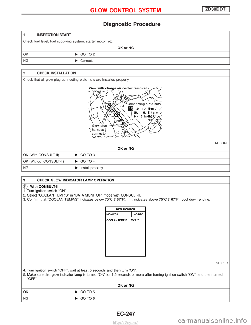
2 CHECK INSTALLATION
Check that all glow plug connecting plate nuts are installed properly.
MEC002E
OK or NG
OK (With CONSULT-II) EGO TO 3.
OK (Without CONSULT-II) EGO TO 4.
NG EInstall properly.
3 CHECK GLOW INDICATOR LAMP OPERATION
With CONSULT-II
1. Turn ignition switch ªONº.
2. Select ªCOOLAN TEMP/Sº in ªDATA MONITORº mode with CONSULT-II.
3. Confirm that ªCOOLAN TEMP/Sº indicates below 75ÉC (167ÉF). If it indicates above 75ÉC (167ÉF), cool down engine.
SEF013Y
4. Turn ignition switch ªOFFº, wait at least 5 seconds and then turn ªONº.
5. Make sure that glow indicator lamp is turned ªONº for 1.5 seconds or more after turning ignition switch ªONº, and then turned ªOFFº.
OK or NG
OK EGO TO 5.
NG EGO TO 6.
GLOW CONTROL SYSTEMZD30DDTi
EC-247
http://vnx.su/
Page 523 of 1833
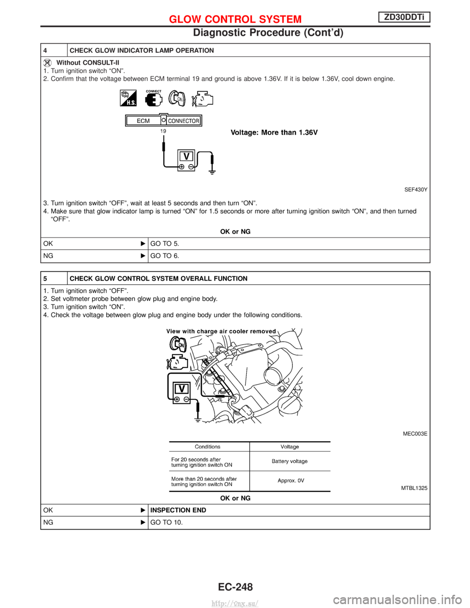
4 CHECK GLOW INDICATOR LAMP OPERATION
Without CONSULT-II
1. Turn ignition switch ªONº.
2. Confirm that the voltage between ECM terminal 19 and ground is above 1.36V. If it is below 1.36V, cool down engine.
SEF430Y
3. Turn ignition switch ªOFFº, wait at least 5 seconds and then turn ªONº.
4. Make sure that glow indicator lamp is turned ªONº for 1.5 seconds or more after turning ignition switch ªONº, and then turned ªOFFº.
OK or NG
OK EGO TO 5.
NG EGO TO 6.
5 CHECK GLOW CONTROL SYSTEM OVERALL FUNCTION
1. Turn ignition switch ªOFFº.
2. Set voltmeter probe between glow plug and engine body.
3. Turn ignition switch ªONº.
4. Check the voltage between glow plug and engine body under the following conditions.
MEC003E
MTBL1325
OK or NG
OK EINSPECTION END
NG EGO TO 10.
GLOW CONTROL SYSTEMZD30DDTi
Diagnostic Procedure (Cont'd)
EC-248
http://vnx.su/
Page 526 of 1833
13 DETECT MALFUNCTIONING PART
Check the following.
IHarness connectors M787, F66 (LHD models)
I Harness for open or short between glow relay and ECM
ERepair open circuit or short to ground or short to power in harness or connectors.
14 CHECK HARNESS CONTINUITY BETWEEN GLOW RELAY AND GLOW PLUG FOR OPEN AND SHORT
1. Disconnect glow plug harness connector.
2. Check harness continuity between glow relay terminal 3 and glow plug harness connector. Refer to Wiring Diagram.
Continuity should exist.
3. Also check harness for short to ground and short to power.
OK or NG
OK EGO TO 16.
NG EGO TO 15.
15 DETECT MALFUNCTIONING PART
Check the following.
IHarness connectors M45, E202
I Harness connectors E230, E241
I Harness for open or short between glow relay and glow plug
ERepair open circuit or short to ground or short to power in harness or connectors.
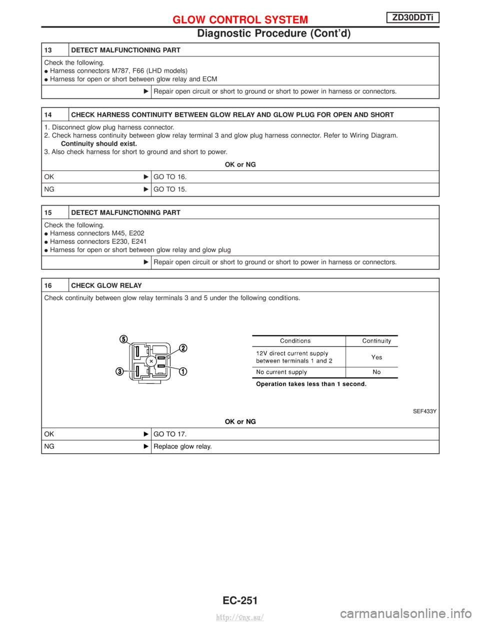
16 CHECK GLOW RELAY
Check continuity between glow relay terminals 3 and 5 under the following conditions.
SEF433Y
OK or NG
OK EGO TO 17.
NG EReplace glow relay.
GLOW CONTROL SYSTEMZD30DDTi
Diagnostic Procedure (Cont'd)
EC-251
http://vnx.su/