Page 527 of 1833
17 CHECK GLOW PLUG
1. Remove glow plug connecting plate.
2. Check glow plug resistance.
MEC005EResistance: Approx. 0.5W[at 20ÉC (68ÉF)]
NOTE:
I Do not bump glow plug heating element. If it is bumped, replace glow plug with a new one.
I If glow plug is dropped from a height of 10 cm (3.94 in) or higher, replace with a new one.
I If glow plug installation hole is contaminated with carbon, remove it with a reamer or suitable tool.
I Hand-tighten glow plug by turning it two or three times, then tighten using a tool to specified torque.
:15-20N ×m (1.5 - 2.1 kg-m, 11 - 15 ft-lb)
OK or NG
OK EGO TO 18.
NG EReplace glow plug.
18 CHECK INTERMITTENT INCIDENT
Refer to ªTROUBLE DIAGNOSIS FOR INTERMITTENT INCIDENTº, EC-78.
EINSPECTION END
GLOW CONTROL SYSTEMZD30DDTi
Diagnostic Procedure (Cont'd)
EC-252
http://vnx.su/
Page 587 of 1833
General Specifications
Unit: rpm
EngineZD30DDTi
Idle speed 750 25
Maximum engine speed 4,300
Injection Pump Numbers
EnginePart numberPump assembly number
ZD30DDTi 16700 VG100 109342-4023
Injection Nozzle
Unit: kPa (bar, kg/cm2, psi)
Initial injection pressureUsed 19,026 (190.3, 194, 2,759)
New 19,516 - 20,497 (195.2 - 205.0, 199 - 209, 2,830 - 2,972)
Limit 16,182 (161.8, 165, 2,346)
Engine Coolant Temperature Sensor
Temperature ÉC (ÉF)
Resistance kW
20 (68) 2.1 - 2.9
50 (122) 0.68 - 1.00
90 (194) 0.236 - 0.260
Crankshaft Position Sensor (TDC)
Resistance [at 20ÉC (68ÉF)] W 1,287 - 1,573
Glow Plug
Resistance [at 20ÉC (68ÉF)]W Approximately 0.5
Accelerator Position Sensor
Throttle valve conditionsResistance between terminals 2 and 3 kW[at 25ÉC (77ÉF)]
Completely closed Approximately 0.5
Partially open 0.5-4
Completely open Approximately 4
EGR Volume Control Valve
Resistance [at 25ÉC (77ÉF)]W 13-17
SERVICE DATA AND SPECIFICATIONS (SDS)ZD30DDTi
EC-312
http://vnx.su/
Page 609 of 1833
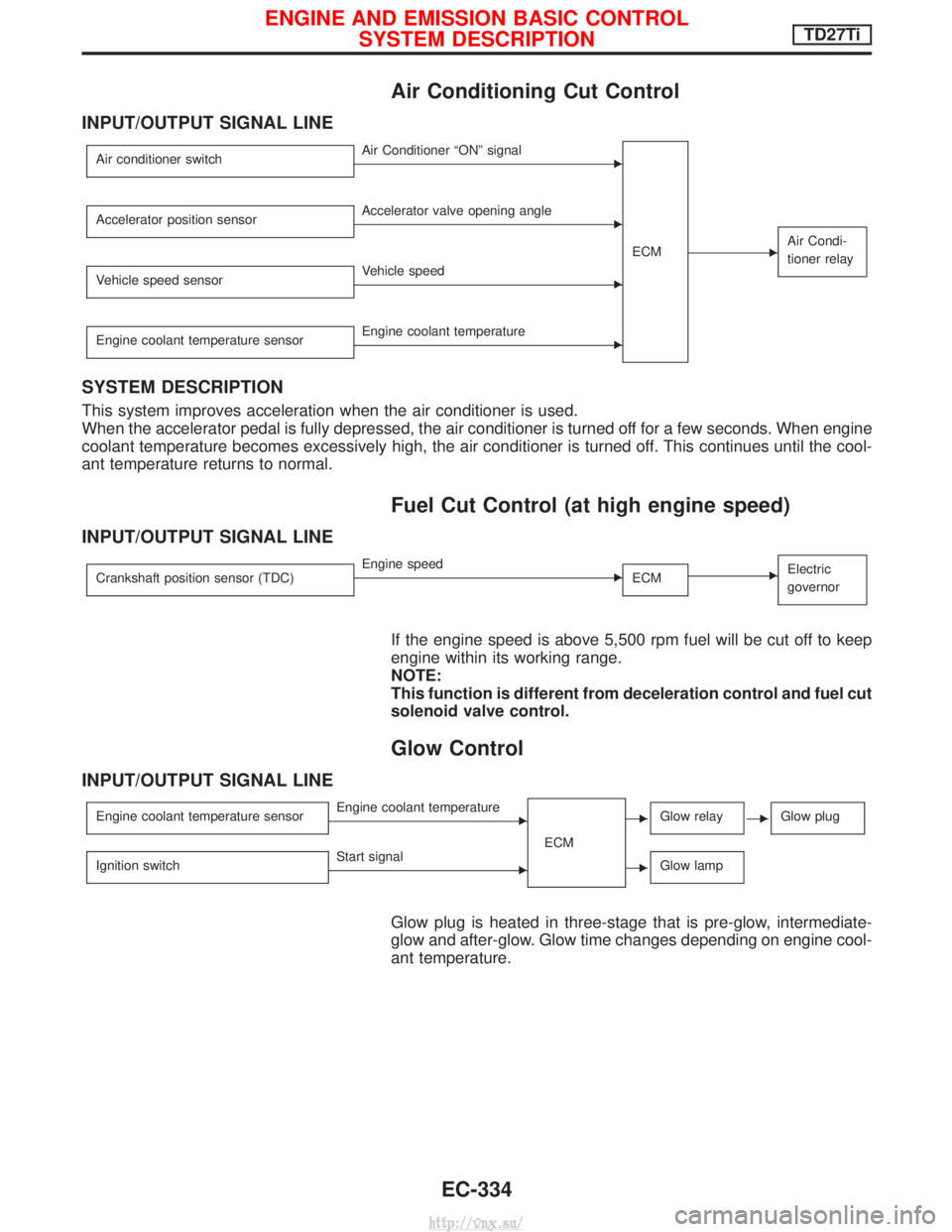
Air Conditioning Cut Control
INPUT/OUTPUT SIGNAL LINE
Air conditioner switchEAir Conditioner ªONº signalECM
EAir Condi-
tioner relay
Accelerator position sensorEAccelerator valve opening angle
Vehicle speed sensor
EVehicle speed
Engine coolant temperature sensor
EEngine coolant temperature
SYSTEM DESCRIPTION
This system improves acceleration when the air conditioner is used.
When the accelerator pedal is fully depressed, the air conditioner is turned off for a few seconds. When engine
coolant temperature becomes excessively high, the air conditioner is turned off. This continues until the cool-
ant temperature returns to normal.
Fuel Cut Control (at high engine speed)
INPUT/OUTPUT SIGNAL LINE
Crankshaft position sensor (TDC)EEngine speed ECMEElectric
governor
If the engine speed is above 5,500 rpm fuel will be cut off to keep
engine within its working range.
NOTE:
This function is different from deceleration control and fuel cut
solenoid valve control.
Glow Control
INPUT/OUTPUT SIGNAL LINE
Engine coolant temperature sensorEEngine coolant temperature
ECMEGlow relayEGlow plug
Ignition switchEStart signalEGlow lamp
Glow plug is heated in three-stage that is pre-glow, intermediate-
glow and after-glow. Glow time changes depending on engine cool-
ant temperature.
ENGINE AND EMISSION BASIC CONTROLSYSTEM DESCRIPTIONTD27Ti
EC-334
http://vnx.su/
Page 687 of 1833
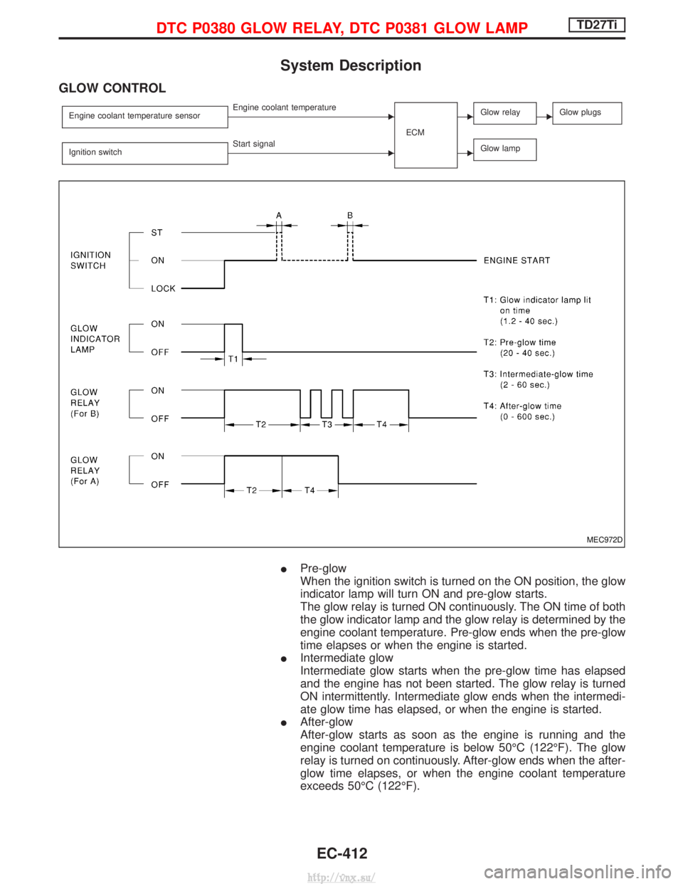
System Description
GLOW CONTROL
Engine coolant temperature sensorEEngine coolant temperatureECMEGlow relayEGlow plugs
Ignition switchEStart signalEGlow lamp
IPre-glow
When the ignition switch is turned on the ON position, the glow
indicator lamp will turn ON and pre-glow starts.
The glow relay is turned ON continuously. The ON time of both
the glow indicator lamp and the glow relay is determined by the
engine coolant temperature. Pre-glow ends when the pre-glow
time elapses or when the engine is started.
I Intermediate glow
Intermediate glow starts when the pre-glow time has elapsed
and the engine has not been started. The glow relay is turned
ON intermittently. Intermediate glow ends when the intermedi-
ate glow time has elapsed, or when the engine is started.
I After-glow
After-glow starts as soon as the engine is running and the
engine coolant temperature is below 50ÉC (122ÉF). The glow
relay is turned on continuously. After-glow ends when the after-
glow time elapses, or when the engine coolant temperature
exceeds 50ÉC (122ÉF).
MEC972D
DTC P0380 GLOW RELAY, DTC P0381 GLOW LAMPTD27Ti
EC-412
http://vnx.su/
Page 688 of 1833
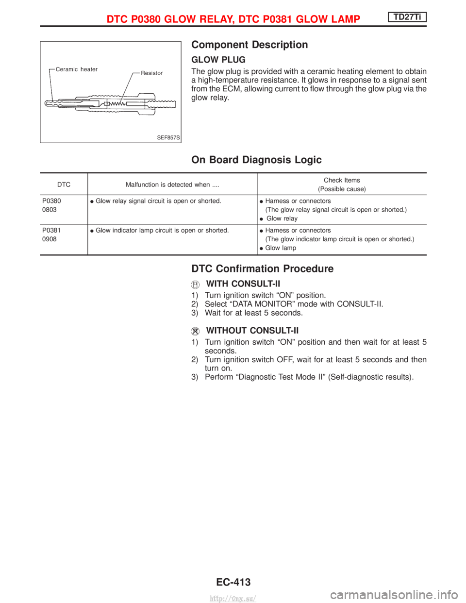
Component Description
GLOW PLUG
The glow plug is provided with a ceramic heating element to obtain
a high-temperature resistance. It glows in response to a signal sent
from the ECM, allowing current to flow through the glow plug via the
glow relay.
On Board Diagnosis Logic
DTCMalfunction is detected when .... Check Items
(Possible cause)
P0380
0803 I
Glow relay signal circuit is open or shorted. IHarness or connectors
(The glow relay signal circuit is open or shorted.)
I Glow relay
P0381
0908 I
Glow indicator lamp circuit is open or shorted. IHarness or connectors
(The glow indicator lamp circuit is open or shorted.)
I Glow lamp
DTC Confirmation Procedure
WITH CONSULT-II
1) Turn ignition switch ªONº position.
2) Select ªDATA MONITORº mode with CONSULT-II.
3) Wait for at least 5 seconds.
WITHOUT CONSULT-II
1) Turn ignition switch ªONº position and then wait for at least 5
seconds.
2) Turn ignition switch OFF, wait for at least 5 seconds and then turn on.
3) Perform ªDiagnostic Test Mode IIº (Self-diagnostic results).
SEF857S
DTC P0380 GLOW RELAY, DTC P0381 GLOW LAMPTD27Ti
EC-413
http://vnx.su/
Page 691 of 1833
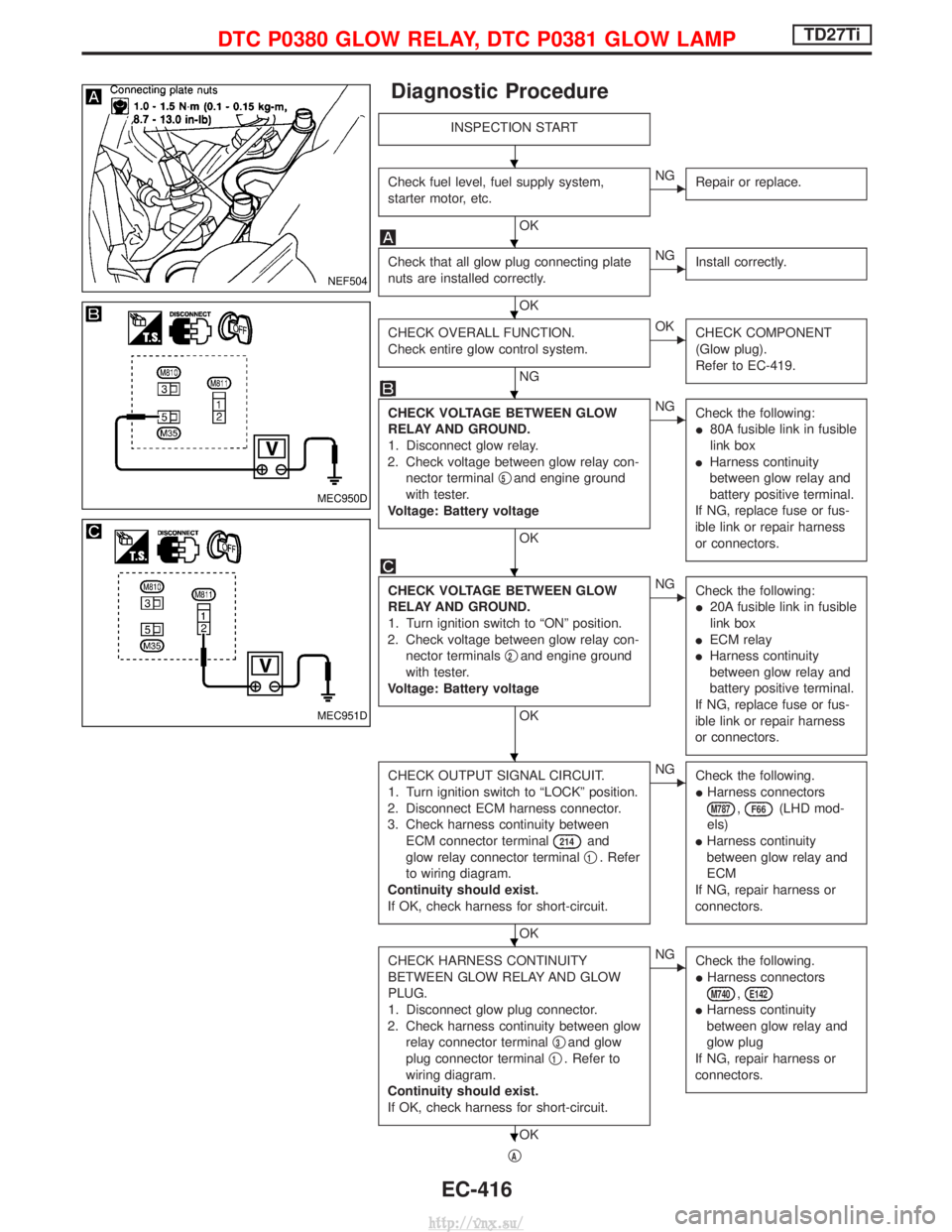
Diagnostic Procedure
INSPECTION START
Check fuel level, fuel supply system,
starter motor, etc.
OK
ENGRepair or replace.
Check that all glow plug connecting plate
nuts are installed correctly.
OK
ENGInstall correctly.
CHECK OVERALL FUNCTION.
Check entire glow control system.
NG
EOKCHECK COMPONENT
(Glow plug).
Refer to EC-419.
CHECK VOLTAGE BETWEEN GLOW
RELAY AND GROUND.
1. Disconnect glow relay.
2. Check voltage between glow relay con- nector terminal q
5and engine ground
with tester.
Voltage: Battery voltage
OK
ENG Check the following:
I80A fusible link in fusible
link box
I Harness continuity
between glow relay and
battery positive terminal.
If NG, replace fuse or fus-
ible link or repair harness
or connectors.
CHECK VOLTAGE BETWEEN GLOW
RELAY AND GROUND.
1. Turn ignition switch to ªONº position.
2. Check voltage between glow relay con- nector terminals q
2and engine ground
with tester.
Voltage: Battery voltage
OK
ENG Check the following:
I20A fusible link in fusible
link box
I ECM relay
I Harness continuity
between glow relay and
battery positive terminal.
If NG, replace fuse or fus-
ible link or repair harness
or connectors.
CHECK OUTPUT SIGNAL CIRCUIT.
1. Turn ignition switch to ªLOCKº position.
2. Disconnect ECM harness connector.
3. Check harness continuity between ECM connector terminal
214and
glow relay connector terminal q
1. Refer
to wiring diagram.
Continuity should exist.
If OK, check harness for short-circuit.
OK
ENG Check the following.
IHarness connectors
M787,F66(LHD mod-
els)
I Harness continuity
between glow relay and
ECM
If NG, repair harness or
connectors.
CHECK HARNESS CONTINUITY
BETWEEN GLOW RELAY AND GLOW
PLUG.
1. Disconnect glow plug connector.
2. Check harness continuity between glow relay connector terminal q
3and glow
plug connector terminal q
1. Refer to
wiring diagram.
Continuity should exist.
If OK, check harness for short-circuit.
OK
ENG Check the following.
IHarness connectors
M740,E142
IHarness continuity
between glow relay and
glow plug
If NG, repair harness or
connectors.
qA
NEF504
MEC950D
MEC951D
H
H
H
H
H
H
H
H
DTC P0380 GLOW RELAY, DTC P0381 GLOW LAMPTD27Ti
EC-416
http://vnx.su/
Page 692 of 1833
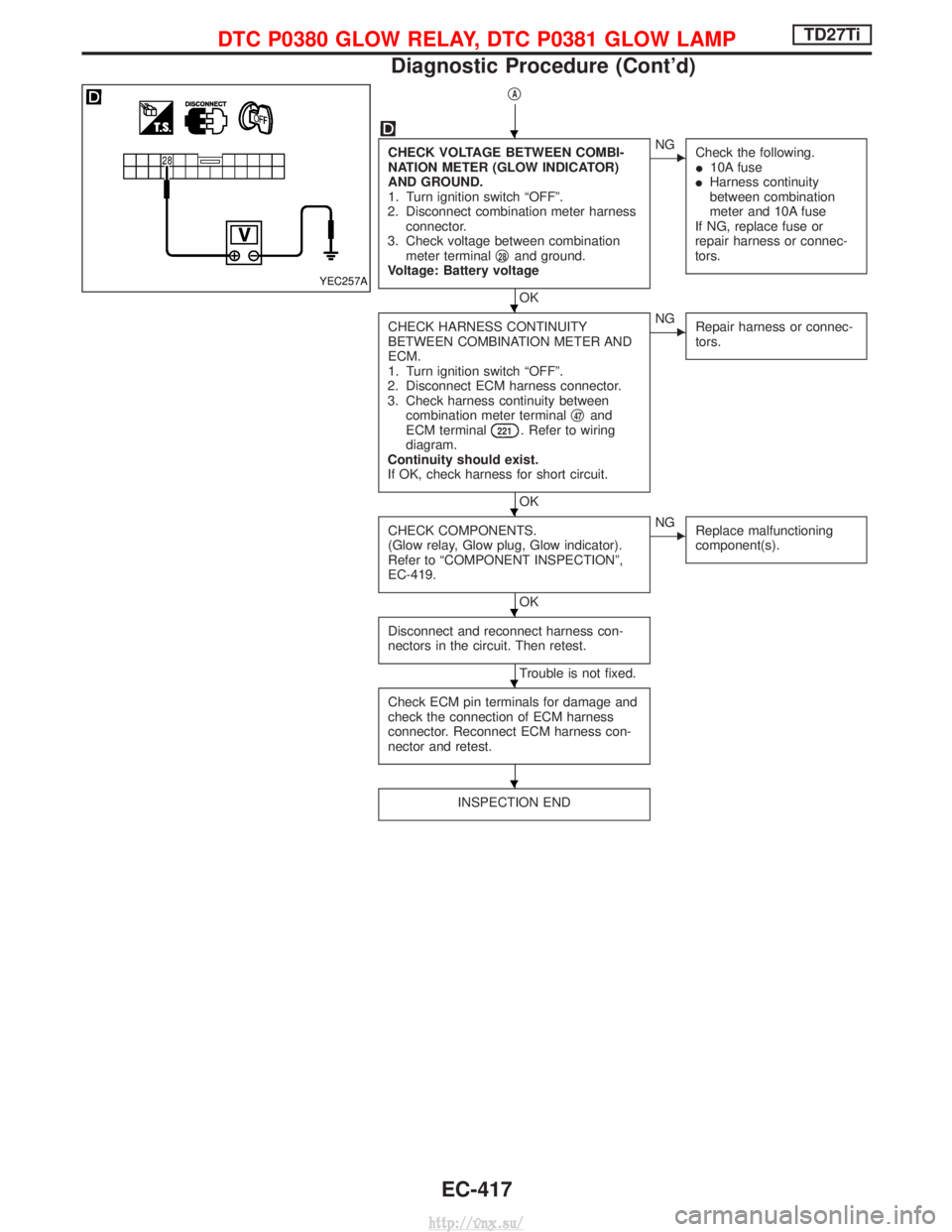
qA
CHECK VOLTAGE BETWEEN COMBI-
NATION METER (GLOW INDICATOR)
AND GROUND.
1. Turn ignition switch ªOFFº.
2. Disconnect combination meter harness connector.
3. Check voltage between combination meter terminal q
28and ground.
Voltage: Battery voltage
OK
ENG Check the following.
I10A fuse
I Harness continuity
between combination
meter and 10A fuse
If NG, replace fuse or
repair harness or connec-
tors.
CHECK HARNESS CONTINUITY
BETWEEN COMBINATION METER AND
ECM.
1. Turn ignition switch ªOFFº.
2. Disconnect ECM harness connector.
3. Check harness continuity between combination meter terminal q
47and
ECM terminal221. Refer to wiring
diagram.
Continuity should exist.
If OK, check harness for short circuit.
OK
ENG Repair harness or connec-
tors.
CHECK COMPONENTS.
(Glow relay, Glow plug, Glow indicator).
Refer to ªCOMPONENT INSPECTIONº,
EC-419.
OK
ENGReplace malfunctioning
component(s).
Disconnect and reconnect harness con-
nectors in the circuit. Then retest.
Trouble is not fixed.
Check ECM pin terminals for damage and
check the connection of ECM harness
connector. Reconnect ECM harness con-
nector and retest.
INSPECTION END
YEC257A
H
H
H
H
H
H
DTC P0380 GLOW RELAY, DTC P0381 GLOW LAMPTD27Ti
Diagnostic Procedure (Cont'd)
EC-417
http://vnx.su/
Page 693 of 1833
System Operation Check
Set voltmeter between glow plug and engine body.
1. Pre-glow control
a. Turn ignition switch to ªONº position.
b. Read voltage and time.Battery voltage will continuously appear for about 20*
seconds after ignition switch is turned ªONº.
* Engine coolant temperature is higher than 20ÉC(68ÉF).
* Repeatedly turning the ignition switch to ªONº posi- tion and then back to ªLOCKº position may change
the glow time.
2. Intermediate-glow control
a. Turn ignition switch to ªLOCKº position. Wait at least 5 seconds.
b. Turn ignition switch to ªONº.
c. Read voltage. Battery voltage will intermittently appear for about 60
seconds after pre-glow control time has elapsed.
3. After-glow control Start engine and read voltage and time.Battery voltage will appear for max. 10 minutes.
When engine coolant temperature is lower than 50ÉC
(122ÉF).
NEF506
NEF726
NEF727
NEF728
DTC P0380 GLOW RELAY, DTC P0381 GLOW LAMPTD27Ti
EC-418
http://vnx.su/