2004 NISSAN TERRANO turn signal relay
[x] Cancel search: turn signal relayPage 687 of 1833
System Description
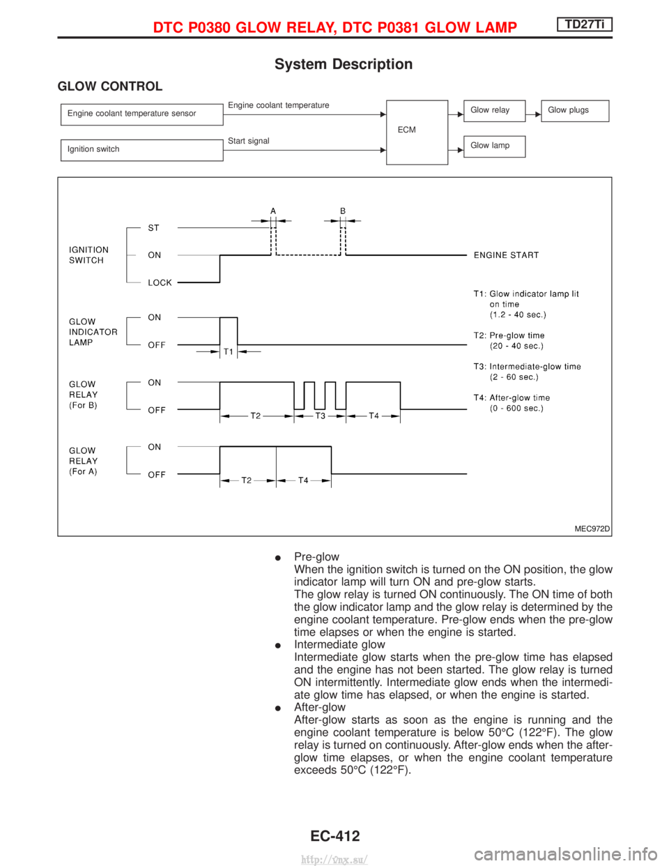
GLOW CONTROL
Engine coolant temperature sensorEEngine coolant temperatureECMEGlow relayEGlow plugs
Ignition switchEStart signalEGlow lamp
IPre-glow
When the ignition switch is turned on the ON position, the glow
indicator lamp will turn ON and pre-glow starts.
The glow relay is turned ON continuously. The ON time of both
the glow indicator lamp and the glow relay is determined by the
engine coolant temperature. Pre-glow ends when the pre-glow
time elapses or when the engine is started.
I Intermediate glow
Intermediate glow starts when the pre-glow time has elapsed
and the engine has not been started. The glow relay is turned
ON intermittently. Intermediate glow ends when the intermedi-
ate glow time has elapsed, or when the engine is started.
I After-glow
After-glow starts as soon as the engine is running and the
engine coolant temperature is below 50ÉC (122ÉF). The glow
relay is turned on continuously. After-glow ends when the after-
glow time elapses, or when the engine coolant temperature
exceeds 50ÉC (122ÉF).
MEC972D
DTC P0380 GLOW RELAY, DTC P0381 GLOW LAMPTD27Ti
EC-412
http://vnx.su/
Page 688 of 1833
Component Description
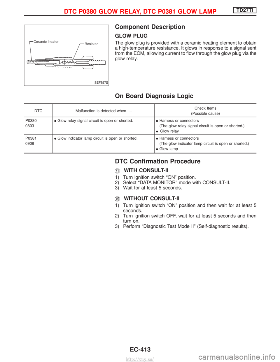
GLOW PLUG
The glow plug is provided with a ceramic heating element to obtain
a high-temperature resistance. It glows in response to a signal sent
from the ECM, allowing current to flow through the glow plug via the
glow relay.
On Board Diagnosis Logic
DTCMalfunction is detected when .... Check Items
(Possible cause)
P0380
0803 I
Glow relay signal circuit is open or shorted. IHarness or connectors
(The glow relay signal circuit is open or shorted.)
I Glow relay
P0381
0908 I
Glow indicator lamp circuit is open or shorted. IHarness or connectors
(The glow indicator lamp circuit is open or shorted.)
I Glow lamp
DTC Confirmation Procedure
WITH CONSULT-II
1) Turn ignition switch ªONº position.
2) Select ªDATA MONITORº mode with CONSULT-II.
3) Wait for at least 5 seconds.
WITHOUT CONSULT-II
1) Turn ignition switch ªONº position and then wait for at least 5
seconds.
2) Turn ignition switch OFF, wait for at least 5 seconds and then turn on.
3) Perform ªDiagnostic Test Mode IIº (Self-diagnostic results).
SEF857S
DTC P0380 GLOW RELAY, DTC P0381 GLOW LAMPTD27Ti
EC-413
http://vnx.su/
Page 691 of 1833
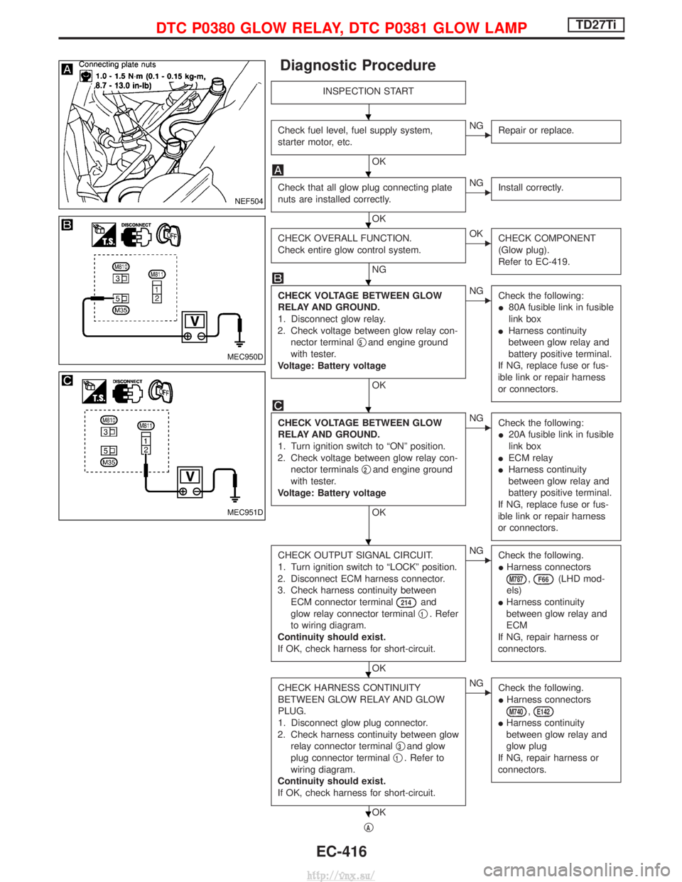
Diagnostic Procedure
INSPECTION START
Check fuel level, fuel supply system,
starter motor, etc.
OK
ENGRepair or replace.
Check that all glow plug connecting plate
nuts are installed correctly.
OK
ENGInstall correctly.
CHECK OVERALL FUNCTION.
Check entire glow control system.
NG
EOKCHECK COMPONENT
(Glow plug).
Refer to EC-419.
CHECK VOLTAGE BETWEEN GLOW
RELAY AND GROUND.
1. Disconnect glow relay.
2. Check voltage between glow relay con- nector terminal q
5and engine ground
with tester.
Voltage: Battery voltage
OK
ENG Check the following:
I80A fusible link in fusible
link box
I Harness continuity
between glow relay and
battery positive terminal.
If NG, replace fuse or fus-
ible link or repair harness
or connectors.
CHECK VOLTAGE BETWEEN GLOW
RELAY AND GROUND.
1. Turn ignition switch to ªONº position.
2. Check voltage between glow relay con- nector terminals q
2and engine ground
with tester.
Voltage: Battery voltage
OK
ENG Check the following:
I20A fusible link in fusible
link box
I ECM relay
I Harness continuity
between glow relay and
battery positive terminal.
If NG, replace fuse or fus-
ible link or repair harness
or connectors.
CHECK OUTPUT SIGNAL CIRCUIT.
1. Turn ignition switch to ªLOCKº position.
2. Disconnect ECM harness connector.
3. Check harness continuity between ECM connector terminal
214and
glow relay connector terminal q
1. Refer
to wiring diagram.
Continuity should exist.
If OK, check harness for short-circuit.
OK
ENG Check the following.
IHarness connectors
M787,F66(LHD mod-
els)
I Harness continuity
between glow relay and
ECM
If NG, repair harness or
connectors.
CHECK HARNESS CONTINUITY
BETWEEN GLOW RELAY AND GLOW
PLUG.
1. Disconnect glow plug connector.
2. Check harness continuity between glow relay connector terminal q
3and glow
plug connector terminal q
1. Refer to
wiring diagram.
Continuity should exist.
If OK, check harness for short-circuit.
OK
ENG Check the following.
IHarness connectors
M740,E142
IHarness continuity
between glow relay and
glow plug
If NG, repair harness or
connectors.
qA
NEF504
MEC950D
MEC951D
H
H
H
H
H
H
H
H
DTC P0380 GLOW RELAY, DTC P0381 GLOW LAMPTD27Ti
EC-416
http://vnx.su/
Page 736 of 1833
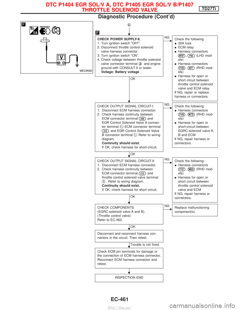
qB
CHECK POWER SUPPLY-II.
1. Turn ignition switch ªOFFº.
2. Disconnect throttle control solenoid valve harness connector.
3. Turn ignition switch ªONº.
4. Check voltage between throttle solenoid valve connector terminal q
2and engine
ground with CONSULT-II or tester.
Voltage: Battery voltage
OK
ENG Check the following.
I20A fuse
I ECM relay
I Harness connectors
M787,F66(LHD mod-
els)
I Harness connectors
F100,M77(RHD mod-
els)
I Harness for open or
short circuit between
throttle control solenoid
valve and ECM relay.
If NG, repair or replace
harness or connectors.
CHECK OUTPUT SIGNAL CIRCUIT-I.
1. Disconnect ECM harness connector.
2. Check harness continuity between ECM connector terminal
208and
EGR Control Solenoid Valve A connec-
tor terminal q
1; ECM connector terminal
210and EGR Control Solenoid Valve
B connector terminal q
1. Refer to wiring
diagram.
Continuity should exist.
If OK, check harness for short-circuit.
OK
ENG Check the following:
IHarness connectors
F100,M775(RHD mod-
els)
I Harness for open or
short-circuit between
EGRC-solenoid valve A,
B and ECM
If NG, repair harness or
connectors.
CHECK OUTPUT SIGNAL CIRCUIT-II.
1. Disconnect ECM harness connector.
2. Check harness continuity between ECM connector terminal
213and
throttle control solenoid valve terminal
q
1. Refer to wiring diagram.
Continuity should exist.
If OK, check harness for short circuit.
OK
ENG Check the following:
IHarness connectors
F137,M853(RHD mod-
els)
I Harness for open or
short circuit between
throttle control solenoid
valve and ECM
If NG, repair harness or
connectors.
CHECK COMPONENTS
(EGRC-solenoid valve A and B).
(Throttle control valve)
Refer to EC-462.
OK
ENG Replace malfunctioning
component(s).
Disconnect and reconnect harness con-
nectors in the circuit. Then retest.
Trouble is not fixed.
Check ECM pin terminals for damage or
the connection of ECM harness connector.
Reconnect ECM harness connector and
retest.
INSPECTION END
MEC954D
H
H
H
H
H
H
H
DTC P1404 EGR SOL/V A, DTC P1405 EGR SOL/V B/P1407 THROTTLE SOLENOID VALVETD27Ti
Diagnostic Procedure (Cont'd)
EC-461
http://vnx.su/
Page 738 of 1833
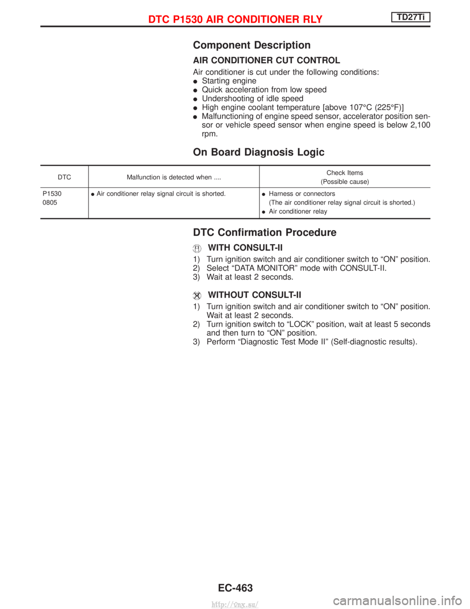
Component Description
AIR CONDITIONER CUT CONTROL
Air conditioner is cut under the following conditions:
IStarting engine
I Quick acceleration from low speed
I Undershooting of idle speed
I High engine coolant temperature [above 107ÉC (225ÉF)]
I Malfunctioning of engine speed sensor, accelerator position sen-
sor or vehicle speed sensor when engine speed is below 2,100
rpm.
On Board Diagnosis Logic
DTC Malfunction is detected when .... Check Items
(Possible cause)
P1530
0805 I
Air conditioner relay signal circuit is shorted. IHarness or connectors
(The air conditioner relay signal circuit is shorted.)
I Air conditioner relay
DTC Confirmation Procedure
WITH CONSULT-II
1) Turn ignition switch and air conditioner switch to ªONº position.
2) Select ªDATA MONITORº mode with CONSULT-II.
3) Wait at least 2 seconds.
WITHOUT CONSULT-II
1) Turn ignition switch and air conditioner switch to ªONº position.
Wait at least 2 seconds.
2) Turn ignition switch to ªLOCKº position, wait at least 5 seconds and then turn to ªONº position.
3) Perform ªDiagnostic Test Mode IIº (Self-diagnostic results).
DTC P1530 AIR CONDITIONER RLYTD27Ti
EC-463
http://vnx.su/
Page 741 of 1833
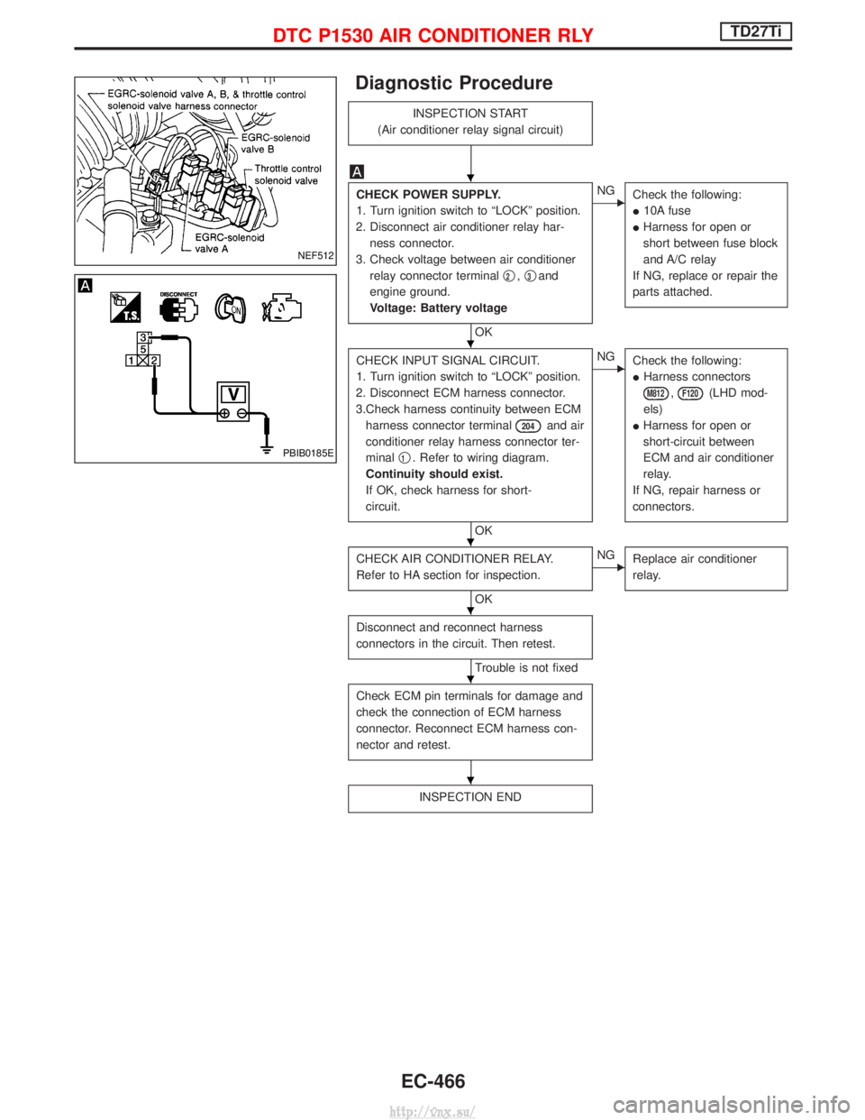
Diagnostic Procedure
INSPECTION START
(Air conditioner relay signal circuit)
CHECK POWER SUPPLY.
1. Turn ignition switch to ªLOCKº position.
2. Disconnect air conditioner relay har- ness connector.
3. Check voltage between air conditioner relay connector terminal q
2,q3and
engine ground.
Voltage: Battery voltage
OK
ENG Check the following:
I10A fuse
I Harness for open or
short between fuse block
and A/C relay
If NG, replace or repair the
parts attached.
CHECK INPUT SIGNAL CIRCUIT.
1. Turn ignition switch to ªLOCKº position.
2. Disconnect ECM harness connector.
3.Check harness continuity between ECM harness connector terminal
204and air
conditioner relay harness connector ter-
minal q
1. Refer to wiring diagram.
Continuity should exist.
If OK, check harness for short-
circuit.
OK
ENG Check the following:
IHarness connectors
M812,F120(LHD mod-
els)
I Harness for open or
short-circuit between
ECM and air conditioner
relay.
If NG, repair harness or
connectors.
CHECK AIR CONDITIONER RELAY.
Refer to HA section for inspection.
OK
ENG Replace air conditioner
relay.
Disconnect and reconnect harness
connectors in the circuit. Then retest.
Trouble is not fixed
Check ECM pin terminals for damage and
check the connection of ECM harness
connector. Reconnect ECM harness con-
nector and retest.
INSPECTION END
NEF512
PBIB0185E
H
H
H
H
H
H
DTC P1530 AIR CONDITIONER RLYTD27Ti
EC-466
http://vnx.su/
Page 744 of 1833
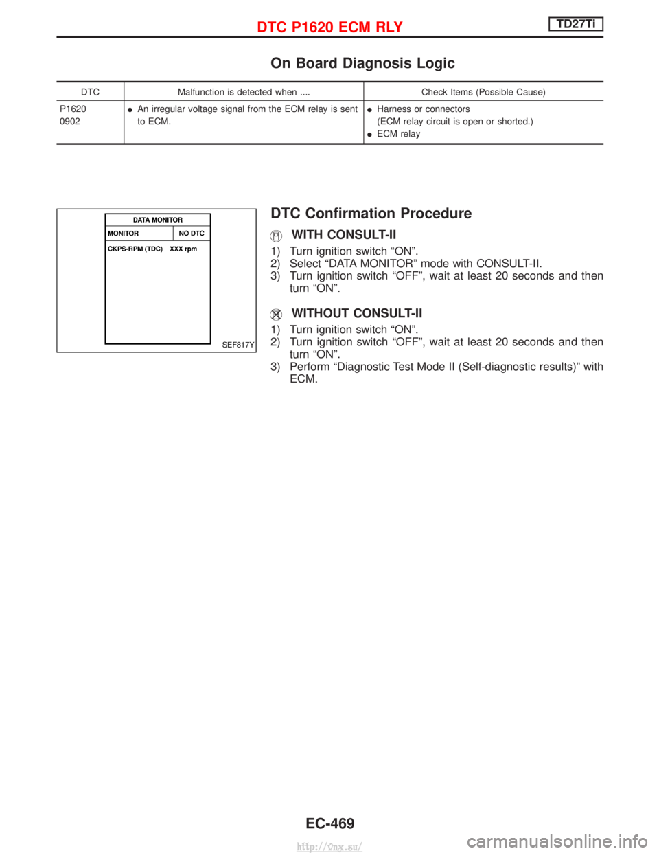
On Board Diagnosis Logic
DTCMalfunction is detected when .... Check Items (Possible Cause)
P1620
0902 I
An irregular voltage signal from the ECM relay is sent
to ECM. I
Harness or connectors
(ECM relay circuit is open or shorted.)
I ECM relay
DTC Confirmation Procedure
WITH CONSULT-II
1) Turn ignition switch ªONº.
2) Select ªDATA MONITORº mode with CONSULT-II.
3) Turn ignition switch ªOFFº, wait at least 20 seconds and then
turn ªONº.
WITHOUT CONSULT-II
1) Turn ignition switch ªONº.
2) Turn ignition switch ªOFFº, wait at least 20 seconds and thenturn ªONº.
3) Perform ªDiagnostic Test Mode II (Self-diagnostic results)º with ECM.
SEF817Y
DTC P1620 ECM RLYTD27Ti
EC-469
http://vnx.su/
Page 746 of 1833
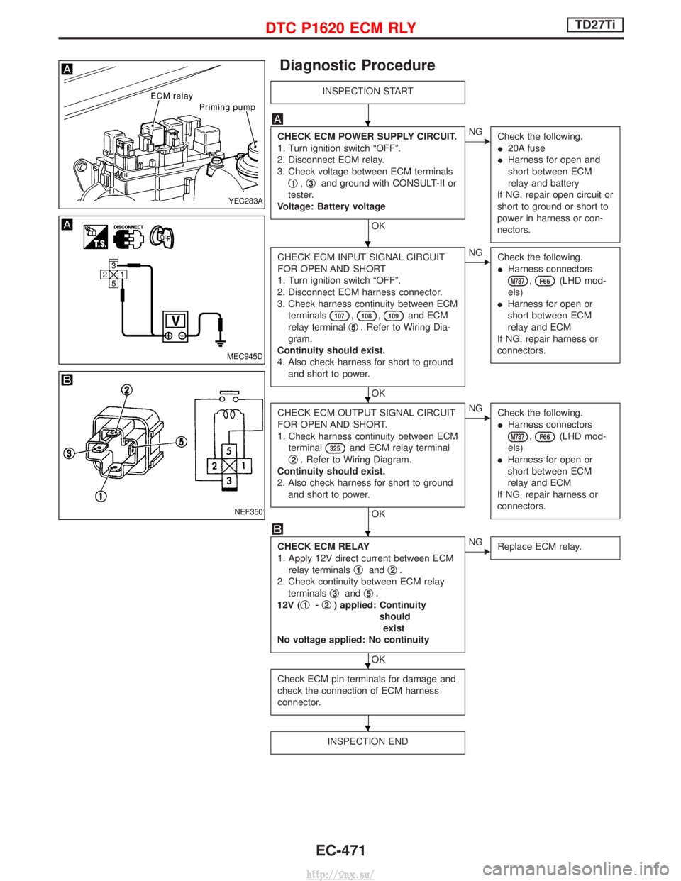
Diagnostic Procedure
INSPECTION START
CHECK ECM POWER SUPPLY CIRCUIT.
1. Turn ignition switch ªOFFº.
2. Disconnect ECM relay.
3. Check voltage between ECM terminals q
1,q3and ground with CONSULT-II or
tester.
Voltage: Battery voltage
OK
ENG Check the following.
I20A fuse
I Harness for open and
short between ECM
relay and battery
If NG, repair open circuit or
short to ground or short to
power in harness or con-
nectors.
CHECK ECM INPUT SIGNAL CIRCUIT
FOR OPEN AND SHORT
1. Turn ignition switch ªOFFº.
2. Disconnect ECM harness connector.
3. Check harness continuity between ECM terminals
107,108,109and ECM
relay terminal q
5. Refer to Wiring Dia-
gram.
Continuity should exist.
4. Also check harness for short to ground and short to power.
OK
ENG Check the following.
IHarness connectors
M787,F66(LHD mod-
els)
I Harness for open or
short between ECM
relay and ECM
If NG, repair harness or
connectors.
CHECK ECM OUTPUT SIGNAL CIRCUIT
FOR OPEN AND SHORT.
1. Check harness continuity between ECM terminal
325and ECM relay terminal
q
2. Refer to Wiring Diagram.
Continuity should exist.
2. Also check harness for short to ground and short to power.
OK
ENG Check the following.
IHarness connectors
M787,F66(LHD mod-
els)
I Harness for open or
short between ECM
relay and ECM
If NG, repair harness or
connectors.
CHECK ECM RELAY
1. Apply 12V direct current between ECM relay terminals q
1andq2.
2. Check continuity between ECM relay terminals q
3andq5.
12V ( q
1-q2) applied: Continuity
shouldexist
No voltage applied: No continuity
OK
ENG Replace ECM relay.
Check ECM pin terminals for damage and
check the connection of ECM harness
connector.
INSPECTION END
YEC283A
MEC945D
NEF350
H
H
H
H
H
H
DTC P1620 ECM RLYTD27Ti
EC-471
http://vnx.su/