2004 NISSAN TERRANO turn signal relay
[x] Cancel search: turn signal relayPage 1228 of 1833
![NISSAN TERRANO 2004 Service Repair Manual SELF-DIAGNOSTIC RESULTS MODE
Diagnostic itemDiagnostic item is detected when... Diagnostic
procedure
FR RH SENSORH
[OPEN] I
Circuit for front right wheel sensor is open.
(An abnormally high input volt](/manual-img/5/57394/w960_57394-1227.png "NISSAN TERRANO 2004 Service Repair Manual SELF-DIAGNOSTIC RESULTS MODE
Diagnostic itemDiagnostic item is detected when... Diagnostic
procedure
FR RH SENSORH
[OPEN] I
Circuit for front right wheel sensor is open.
(An abnormally high input volt")
SELF-DIAGNOSTIC RESULTS MODE
Diagnostic itemDiagnostic item is detected when... Diagnostic
procedure
FR RH SENSORH
[OPEN] I
Circuit for front right wheel sensor is open.
(An abnormally high input voltage is entered.) 4
FR LH SENSORH
[OPEN] I
Circuit for front left wheel sensor is open.
(An abnormally high input voltage is entered.) 4
RR RH SENSORH
[OPEN] I
Circuit for rear right sensor is open.
(An abnormally high input voltage is entered.) 4
RR LH SENSORH
[OPEN] I
Circuit for rear left sensor is open.
(An abnormally high input voltage is entered.) 4
FR RH SENSORH
[SHORT] I
Circuit for front right wheel sensor is shorted.
(An abnormally low input voltage is entered.) 4
FR LH SENSORH
[SHORT] I
Circuit for front left wheel sensor is shorted.
(An abnormally low input voltage is entered.) 4
RR RH SENSORH
[SHORT] I
Circuit for rear right sensor is shorted.
(An abnormally low input voltage is entered.) 4
RR LH SENSORH
[SHORT] I
Circuit for rear left sensor is shorted.
(An abnormally low input voltage is entered.) 4
ABS SENSORH
[ABNORMAL SIGNAL] I
Teeth damage on sensor rotor or misalignment of wheel sensor.
(Abnormal wheel sensor signal is entered.) 4
FR RH IN ABS SOL
[OPEN, SHORT] I
Circuit for front right inlet solenoid valve is open or shorted.
(An abnormally low output voltage is entered.) 3
FR LH IN ABS SOL
[OPEN, SHORT] I
Circuit for front left inlet solenoid valve is open or shorted.
(An abnormally low output voltage is entered.) 3
FR RH OUT ABS SOL
[OPEN, SHORT] I
Circuit for front right outlet solenoid valve is open or shorted.
(An abnormally low output voltage is entered.) 3
FR LH OUT ABS SOL
[OPEN, SHORT] I
Circuit for front left outlet solenoid valve is open or shorted.
(An abnormally low output voltage is entered.) 3
RR IN ABS SOL
[OPEN, SHORT] I
Circuit for rear right outlet solenoid valve is open or shorted.
(An abnormally high output voltage is entered.) 3
RR OUT ABS SOL
[OPEN, SHORT] I
Circuit for rear left outlet solenoid valve is open or shorted.
(An abnormally high output voltage is entered.) 3
ABS ACTUATOR RELAY
[ABNORMAL] I
Actuator solenoid valve relay is ON, even if control unit sends OFF signal.
I Actuator solenoid valve relay is OFF, even if control unit sends ON signal. 6
ABS MOTOR RELAY
[ABNORMAL] I
Circuit for ABS motor relay is open or shorted.
I Circuit for actuator motor is open or shorted.
I Actuator motor relay is stuck. 5
BATTERY VOLT
[VB-LOW] I
Power source voltage supplied to ABS control unit is abnormally low. 7
CONTROL UNIT IFunction of calculation in ABS control unit has failed. 9
G-SENSOR
[ABNORMAL] I
G sensor is open. 8
H If a tire slips on rough roads for more than 10 seconds, the ABS warning lamp may come on. In this case, the malfunctioning code
regarding the wheel sensors may be memorized. Turn off the ignition switch, restart the engine and drive the vehicle at speeds
above 30 km/h (19 MPH).
TROUBLE DIAGNOSES
CONSULT-II Inspection Procedure (Cont'd)
BR-61
http://vnx.su/
Page 1230 of 1833
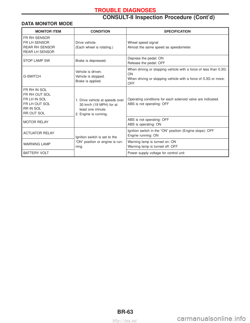
DATA MONITOR MODE
MONITOR ITEMCONDITION SPECIFICATION
FR RH SENSOR
FR LH SENSOR
REAR RH SENSOR
REAR LH SENSOR Drive vehicle.
(Each wheel is rotating.)
Wheel speed signal
Almost the same speed as speedometer.
STOP LAMP SW Brake is depressed. Depress the pedal: ON
Release the pedal: OFF
G-SWITCH Vehicle is driven.
Vehicle is stopped.
Brake is applied.When driving or stopping vehicle with a force of less than 0.3G:
ON
When driving or stopping vehicle with a force of 0.3G or more:
OFF
FR RH IN SOL
FR RH OUT SOL
FR LH IN SOL
FR LH OUT SOL
RR IN SOL
RR OUT SOL 1. Drive vehicle at speeds over
30 km/h (19 MPH) for at
least one minute.
2. Engine is running. Operating conditions for each solenoid valve are indicated.
ABS is not operating: OFF
MOTOR RELAY ABS is not operating: OFF
ABS is operating: ON
ACTUATOR RELAY Ignition switch is set to the
ªONº position or engine is run-
ning.Ignition switch in the ªONº position (Engine stops): OFF
Engine running: ON
WARNING LAMP Warning lamp is turned on: ON
Warning lamp is turned off: OFF
BATTERY VOLT Power supply voltage for control unit
TROUBLE DIAGNOSES
CONSULT-II Inspection Procedure (Cont'd)
BR-63
http://vnx.su/
Page 1514 of 1833
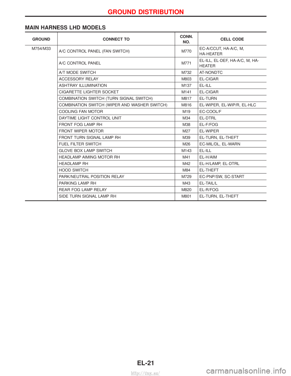
MAIN HARNESS LHD MODELS
GROUNDCONNECT TO CONN.
NO. CELL CODE
M754/M33 A/C CONTROL PANEL (FAN SWITCH) M770EC-A/CCUT, HA-A/C, M,
HA-HEATER
A/C CONTROL PANEL M771EL-ILL, EL-DEF, HA-A/C, M, HA-
HEATER
A/T MODE SWITCH M732 AT-NONDTC
ACCESSORY RELAY M803 EL-CIGAR
ASHTRAY ILLUMINATION M137 EL-ILL
CIGARETTE LIGHTER SOCKET M141 EL-CIGAR
COMBINATION SWITCH (TURN SIGNAL SWITCH) M817 EL-TURN
COMBINATION SWITCH (WIPER AND WASHER SWITCH) M816 EL-WIPER, EL-WIP/R, EL-HLC
COOLING FAN MOTOR M19 EC-COOL/F
DAYTIME LIGHT CONTROL UNIT M34 EL-DTRL
FRONT FOG LAMP RH M38 EL-F/FOG
FRONT WIPER MOTOR M27 EL-WIPER
FRONT TURN SIGNAL LAMP RH M39 EL-TURN, EL-THEFT
FUEL FILTER SWITCH M26 EC-MIL/DL, EL-WARN
GLOVE BOX LAMP SWITCH M143 EL-ILL
HEADLAMP AIMING MOTOR RH M41 EL-H/AIM
HEADLAMP RH M42 EL-H/LAMP, EL-DTRL
HOOD SWITCH M84 EL-THEFT
PARK/NEUTRAL POSITION RELAY M729 EC-PNP/SW, SC-START
PARKING LAMP RH M43 EL-TAIL/L
REAR FOG LAMP RELAY M820 EL-R/FOG
SIDE TURN SIGNAL LAMP RH M801 EL-TURN, EL-THEFT
GROUND DISTRIBUTION
EL-21
http://vnx.su/
Page 1515 of 1833
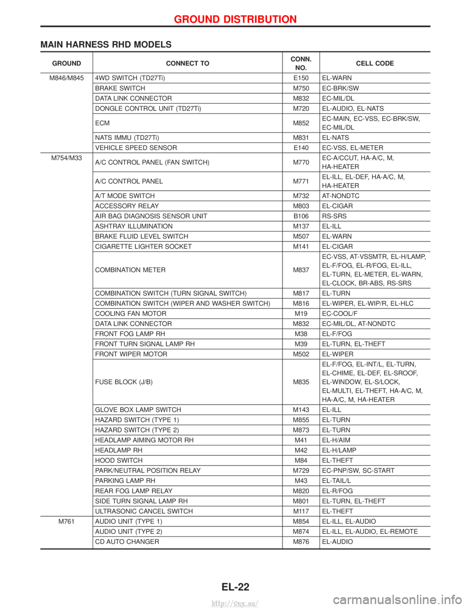
MAIN HARNESS RHD MODELS
GROUNDCONNECT TO CONN.
NO. CELL CODE
M846/M845 4WD SWITCH (TD27Ti) E150 EL-WARN
BRAKE SWITCH M750 EC-BRK/SW
DATA LINK CONNECTOR M832 EC-MIL/DL
DONGLE CONTROL UNIT (TD27Ti) M720 EL-AUDIO, EL-NATS
ECM M852EC-MAIN, EC-VSS, EC-BRK/SW,
EC-MIL/DL
NATS IMMU (TD27Ti) M831 EL-NATS
VEHICLE SPEED SENSOR E140 EC-VSS, EL-METER
M754/M33 A/C CONTROL PANEL (FAN SWITCH) M770EC-A/CCUT, HA-A/C, M,
HA-HEATER
A/C CONTROL PANEL M771EL-ILL, EL-DEF, HA-A/C, M,
HA-HEATER
A/T MODE SWITCH M732 AT-NONDTC
ACCESSORY RELAY M803 EL-CIGAR
AIR BAG DIAGNOSIS SENSOR UNIT B106 RS-SRS
ASHTRAY ILLUMINATION M137 EL-ILL
BRAKE FLUID LEVEL SWITCH M507 EL-WARN
CIGARETTE LIGHTER SOCKET M141 EL-CIGAR
COMBINATION METER M837EC-VSS, AT-VSSMTR, EL-H/LAMP,
EL-F/FOG, EL-R/FOG, EL-ILL,
EL-TURN, EL-METER, EL-WARN,
EL-CLOCK, BR-ABS, RS-SRS
COMBINATION SWITCH (TURN SIGNAL SWITCH) M817 EL-TURN
COMBINATION SWITCH (WIPER AND WASHER SWITCH) M816 EL-WIPER, EL-WIP/R, EL-HLC
COOLING FAN MOTOR M19 EC-COOL/F
DATA LINK CONNECTOR M832 EC-MIL/DL, AT-NONDTC
FRONT FOG LAMP RH M38 EL-F/FOG
FRONT TURN SIGNAL LAMP RH M39 EL-TURN, EL-THEFT
FRONT WIPER MOTOR M502 EL-WIPER
FUSE BLOCK (J/B) M835 EL-F/FOG, EL-INT/L, EL-TURN,
EL-CHIME, EL-DEF, EL-SROOF,
EL-WINDOW, EL-S/LOCK,
EL-MULTI, EL-THEFT, HA-A/C, M,
HA-A/C, M, HA-HEATER
GLOVE BOX LAMP SWITCH M143 EL-ILL
HAZARD SWITCH (TYPE 1) M855 EL-TURN
HAZARD SWITCH (TYPE 2) M873 EL-TURN
HEADLAMP AIMING MOTOR RH M41 EL-H/AIM
HEADLAMP RH M42 EL-H/LAMP
HOOD SWITCH M84 EL-THEFT
PARK/NEUTRAL POSITION RELAY M729 EC-PNP/SW, SC-START
PARKING LAMP RH M43 EL-TAIL/L
REAR FOG LAMP RELAY M820 EL-R/FOG
SIDE TURN SIGNAL LAMP RH M801 EL-TURN, EL-THEFT
ULTRASONIC CANCEL SWITCH M117 EL-THEFT
M761 AUDIO UNIT (TYPE 1) M854 EL-ILL, EL-AUDIO AUDIO UNIT (TYPE 2) M874 EL-ILL, EL-AUDIO, EL-REMOTE
CD AUTO CHANGER M876 EL-AUDIO
GROUND DISTRIBUTION
EL-22
http://vnx.su/
Page 1695 of 1833
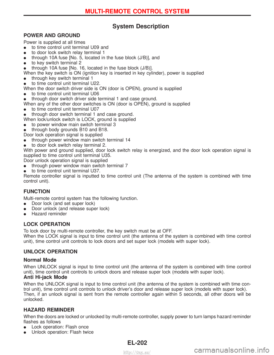
System Description
POWER AND GROUND
Power is supplied at all times
Ito time control unit terminal U09 and
I to door lock switch relay terminal 1
I through 10A fuse [No. 5, located in the fuse block (J/B)], and
I to key switch terminal 2
I through 10A fuse [No. 16, located in the fuse block (J/B)].
When the key switch is ON (ignition key is inserted in key cylinder), power is supplied
I through key switch terminal 1
I to time control unit terminal U22.
When the door switch driver side is ON (door is OPEN), ground is supplied
I to time control unit terminal U06
I through door switch driver side terminal 1 and case ground.
When any of the other door switches is ON (door is OPEN), ground is supplied
I to time control unit terminal U07
I through door switch terminal 1 and case ground.
When lock/unlock switch is LOCK, ground is supplied
I to power window main switch terminal 3
I through body grounds B10 and B18.
Door lock operation signal is supplied
I through power window main switch terminal 14
I to door lock switch relay terminal 2.
With power and ground supplied, door lock switch relay is energized, and the door lock operation signal is
supplied to time control unit terminal U35.
Door unlock operation signal is supplied
I through power window main switch terminal 7
I to time control unit terminal U37.
Remote controller signal is inputted to time control unit (The antenna of the system is combined with time
control unit).
FUNCTION
Multi-remote control system has the following function.
I Door lock (and set super lock)
I Door unlock (and release super lock)
I Hazard reminder
LOCK OPERATION
To lock door by multi-remote controller, the key switch must be at OFF.
When the LOCK signal is input to time control unit (the antenna of the system is combined with time control
unit), time control unit controls to lock doors and set super lock (models with super lock).
UNLOCK OPERATION
Normal Mode
When UNLOCK signal is input to time control unit (the antenna of the system is combined with time control
unit), time control unit controls to unlock doors and release super lock (models with super lock).
Anti Hi-jack Mode
When the UNLOCK signal is input to time control unit (the antenna of the system is combined with time con-
trol unit), time control unit controls to unlock driver's door and release super lock (models with super lock).
Then, if an unlock signal is sent from the remote controller again within 5 seconds, all other doors will be
unlocked.
HAZARD REMINDER
When the doors are locked or unlocked by multi-remote controller, supply power to turn lamps hazard reminder
flashes as follows
ILock operation: Flash once
I Unlock operation: Flash twice
MULTI-REMOTE CONTROL SYSTEM
EL-202
http://vnx.su/
Page 1739 of 1833
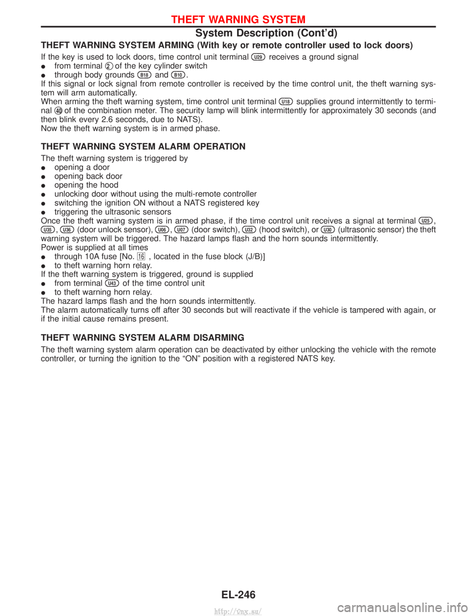
THEFT WARNING SYSTEM ARMING (With key or remote controller used to lock doors)
If the key is used to lock doors, time control unit terminalU29receives a ground signal
I from terminal q
2of the key cylinder switch
I through body grounds
B18andB10.
If this signal or lock signal from remote controller is received by the time control unit, the theft warning sys-
tem will arm automatically.
When arming the theft warning system, time control unit terminal
U18supplies ground intermittently to termi-
nal q
40of the combination meter. The security lamp will blink intermittently for approximately 30 seconds (and
then blink every 2.6 seconds, due to NATS).
Now the theft warning system is in armed phase.
THEFT WARNING SYSTEM ALARM OPERATION
The theft warning system is triggered by
I opening a door
I opening back door
I opening the hood
I unlocking door without using the multi-remote controller
I switching the ignition ON without a NATS registered key
I triggering the ultrasonic sensors
Once the theft warning system is in armed phase, if the time control unit receives a signal at terminal
U25,
U35,U36(door unlock sensor),U06,U07(door switch),U32(hood switch), orU30(ultrasonic sensor) the theft
warning system will be triggered. The hazard lamps flash and the horn sounds intermittently.
Power is supplied at all times
I through 10A fuse [No.
16, located in the fuse block (J/B)]
I to theft warning horn relay.
If the theft warning system is triggered, ground is supplied
I from terminal
U43of the time control unit
I to theft warning horn relay.
The hazard lamps flash and the horn sounds intermittently.
The alarm automatically turns off after 30 seconds but will reactivate if the vehicle is tampered with again, or
if the initial cause remains present.
THEFT WARNING SYSTEM ALARM DISARMING
The theft warning system alarm operation can be deactivated by either unlocking the vehicle with the remote
controller, or turning the ignition to the ªONº position with a registered NATS key.
THEFT WARNING SYSTEM
System Description (Cont'd)
EL-246
http://vnx.su/
Page 1831 of 1833
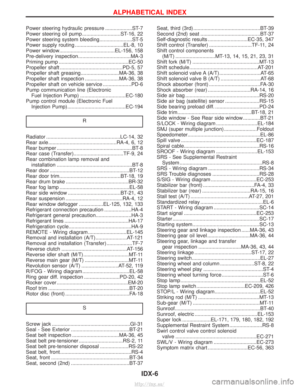
Power steering hydraulic pressure ...................ST-7
Power steering oil pump ...........................ST-16, 22
Power steering system bleeding.......................ST-5
Power supply routing ..................................EL-8, 10
Power window.......................................EL-156, 158
Pre-delivery inspection.....................................MA-3
Priming pump .................................................EC-50
Propeller shaft ............................................PD-5, 57
Propeller shaft greasing...........................MA-36, 38
Propeller shaft inspection ........................MA-36, 38
Propeller shaft on vehicle service ....................PD-6
Pump communication line (ElectronicFuel Injection Pump) ................................EC-180
Pump control module (Electronic Fuel Injection Pump).........................................EC-194
R
Radiator ....................................................LC-14, 32
Rear axle................................................RA-4, 6, 12
Rear bumper .....................................................BT-8
Rear case (Transfer)...................................TF-9, 24
Rear combination lamp removal andinstallation .....................................................BT-8
Rear door ........................................................BT-12
Rear door trim...........................................BT-18, 19
Rear drum brake ............................................BR-32
Rear fog lamp .................................................EL-58
Rear side window .....................................BT-21, 43
Rear suspension ........................................RA-4, 12
Rear window defogger .................EL-125, 132, 133
Refrigerant connection precaution ...................HA-4
Refrigerant general precaution.........................HA-3
Refrigerant lines .............................................HA-17
Refrigeration cycle............................................HA-9
REMOTE - Wiring diagram ...........................EL-145
Removal and installation (A/T)......................AT-121
Removal and installation (Transfer) ..................TF-7
Reverse clutch ..............................................AT-156
Reverse idler shaft (M/T)................................MT-11
Reverse main gear (M/T) ...............................MT-11
Revolution sensor (A/T) ..........................AT-52, 119
R/FOG - Wiring diagram .................................EL-58
Ring gear diff. inspection .........................PD-20, 42
Rocker cover ..................................................EM-20
Roof trim .........................................................BT-20
Rotor disc (front) .............................................FA-18
S
Screw jack .......................................................GI-31
Seal - See Exterior .........................................BT-21
Seat belt inspection .................................MA-36, 45
Seat belt pre-tensioner ...............................RS-2, 11
Seat belt pre-tensioner disposal ....................RS-22
Seat belt, front ..................................................RS-4
Seat, front .......................................................BT-34
Seat, second (2nd) .........................................BT-37 Seat, third (3rd) ...............................................BT-39
Second (2nd) seat ..........................................BT-37
Self-diagnostic results ............................EC-35, 347
Shift control (Transfer) ..............................TF-11, 24
Shift control components
(M/T) ............................MT-13, 14, 15, 21, 23, 31
Shift fork (M/T) ...............................................MT-13
Shift schedule................................................AT-201
Shift solenoid valve A (A/T).............................AT-65
Shift solenoid valve B (A/T) ............................AT-68
Shock absorber (front) ....................................FA-30
Shock absorber (rear) ..............................RA-14, 16
Side air bag ....................................................RS-20
Side air bag (satellite) sensor ........................RS-15
Side bearing preload diff. ...............................PD-24
Side trim....................................................BT-18, 21
Side window - See Rear side window ............BT-21
S/LOCK - Wiring diagram .............................EL-184
SMJ (super multiple junction) .......................Foldout
Speedometer...................................................EL-86
Spill valve .....................................................EC-187
Spiral cable.....................................................RS-16
SROOF - Wiring diagram .............................EL-153
SRS - See Supplemental Restraint System ..........................................................RS-8
SRS - Wiring diagram ....................................RS-34
SRS Trouble diagnoses .................................RS-28
S/SIG - Wiring diagram ................................EC-253
Stabilizer bar (front) ....................................FA-4, 33
Stabilizer bar (rear) ..................................RA-15, 16
Stall test (A/T) .........................................AT-27, 201
Standardized relay ............................................EL-6
START - Wiring diagram ................................SC-14
Start signal ...................................................EC-253
Starter .............................................................SC-17
Starting system...............................................SC-13
Steering gear and linkage inspection ......MA-36, 43
Steering gear oil level ..............................MA-36, 44
Steering gear, linkage and transfer gear inspection ..............................MA-36, 43, 44
Steering linkage ........................................ST-17, 22
Steering switch................................................EL-27
Steering wheel and column ........................ST-8, 22
Steering wheel play ..........................................ST-4
Steering wheel turning force .............................ST-6
Stop lamp ........................................................EL-52
Stop lamp switch ..................................EC-209, 426
STOP/L - Wiring diagram................................EL-52
Striking rod (M/T) ...........................................MT-13
Sub-gear (M/T) ...............................................MT-11
Sunroof............................................................BT-40
Sunroof, electric ............................................EL-153
Super lock ....................EL-171, 179, 180, 182, 192
Supplemental Restraint System .......................RS-8
Swirl control valve control solenoid valve .........................................................EC-271
SWL/V - Wiring diagram ..............................EC-273
Symptom matrix chart ............................EC-56, 363
ALPHABETICAL INDEX
IDX-6
http://vnx.su/