Page 231 of 1833
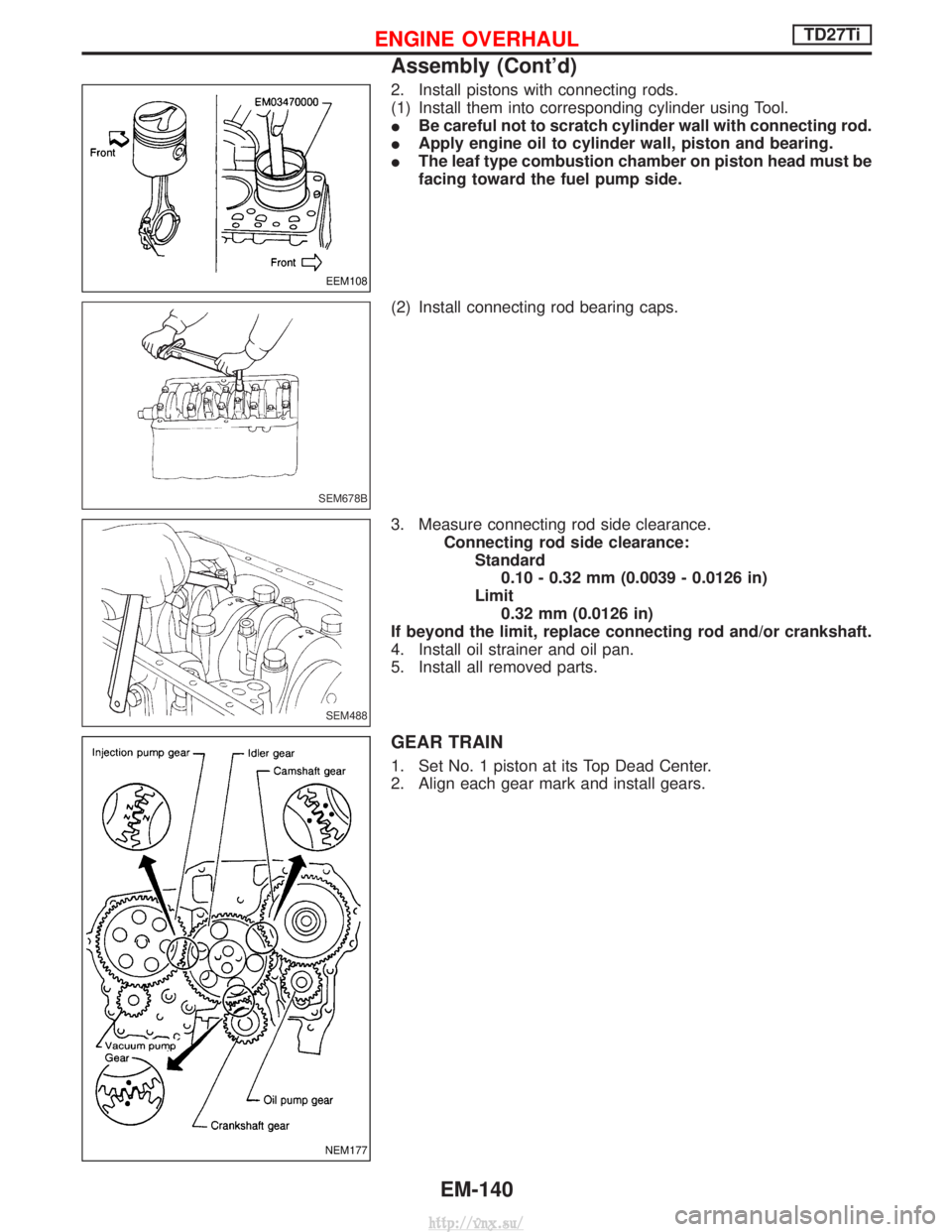
2. Install pistons with connecting rods.
(1) Install them into corresponding cylinder using Tool.
IBe careful not to scratch cylinder wall with connecting rod.
I Apply engine oil to cylinder wall, piston and bearing.
I The leaf type combustion chamber on piston head must be
facing toward the fuel pump side.
(2) Install connecting rod bearing caps.
3. Measure connecting rod side clearance. Connecting rod side clearance:Standard0.10 - 0.32 mm (0.0039 - 0.0126 in)
Limit 0.32 mm (0.0126 in)
If beyond the limit, replace connecting rod and/or crankshaft.
4. Install oil strainer and oil pan.
5. Install all removed parts.
GEAR TRAIN
1. Set No. 1 piston at its Top Dead Center.
2. Align each gear mark and install gears.
EEM108
SEM678B
SEM488
NEM177
ENGINE OVERHAULTD27Ti
Assembly (Cont'd)
EM-140
http://vnx.su/
Page 246 of 1833
Oil Pump
REMOVAL AND INSTALLATION
Refer to ªTIMING GEARº in EM section.
DISASSEMBLY AND ASSEMBLY
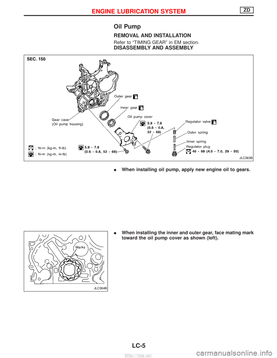
IWhen installing oil pump, apply new engine oil to gears.
I When installing the inner and outer gear, face mating mark
toward the oil pump cover as shown (left).
JLC363B
JLC364B
ENGINE LUBRICATION SYSTEMZD
LC-5
http://vnx.su/
Page 305 of 1833
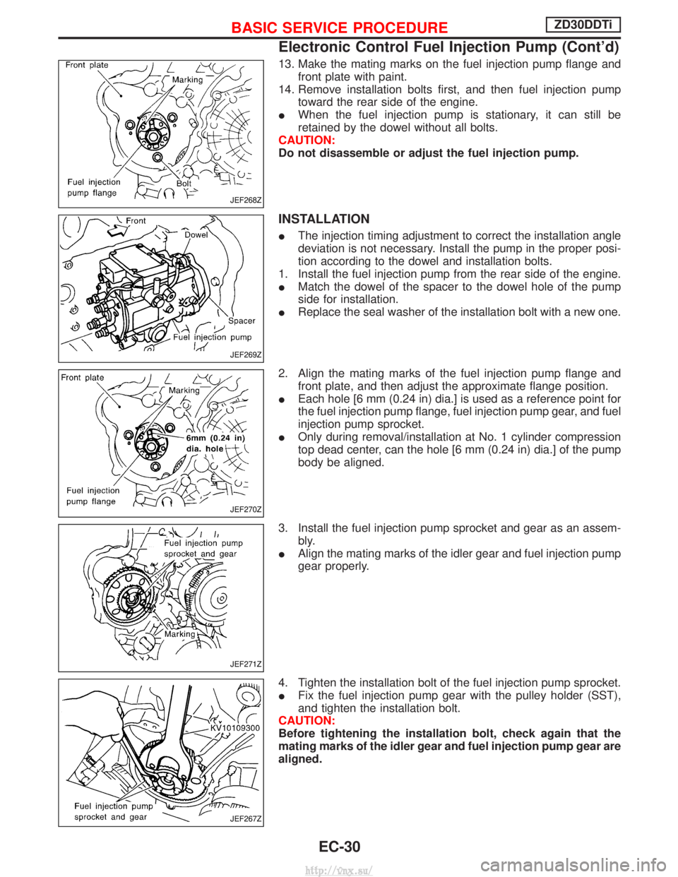
13. Make the mating marks on the fuel injection pump flange andfront plate with paint.
14. Remove installation bolts first, and then fuel injection pump toward the rear side of the engine.
I When the fuel injection pump is stationary, it can still be
retained by the dowel without all bolts.
CAUTION:
Do not disassemble or adjust the fuel injection pump.
INSTALLATION
I The injection timing adjustment to correct the installation angle
deviation is not necessary. Install the pump in the proper posi-
tion according to the dowel and installation bolts.
1. Install the fuel injection pump from the rear side of the engine.
I Match the dowel of the spacer to the dowel hole of the pump
side for installation.
I Replace the seal washer of the installation bolt with a new one.
2. Align the mating marks of the fuel injection pump flange and front plate, and then adjust the approximate flange position.
I Each hole [6 mm (0.24 in) dia.] is used as a reference point for
the fuel injection pump flange, fuel injection pump gear, and fuel
injection pump sprocket.
I Only during removal/installation at No. 1 cylinder compression
top dead center, can the hole [6 mm (0.24 in) dia.] of the pump
body be aligned.
3. Install the fuel injection pump sprocket and gear as an assem- bly.
I Align the mating marks of the idler gear and fuel injection pump
gear properly.
4. Tighten the installation bolt of the fuel injection pump sprocket.
I Fix the fuel injection pump gear with the pulley holder (SST),
and tighten the installation bolt.
CAUTION:
Before tightening the installation bolt, check again that the
mating marks of the idler gear and fuel injection pump gear are
aligned.
JEF268Z
JEF269Z
JEF270Z
JEF271Z
JEF267Z
BASIC SERVICE PROCEDUREZD30DDTi
Electronic Control Fuel Injection Pump (Cont'd)
EC-30
http://vnx.su/
Page 561 of 1833
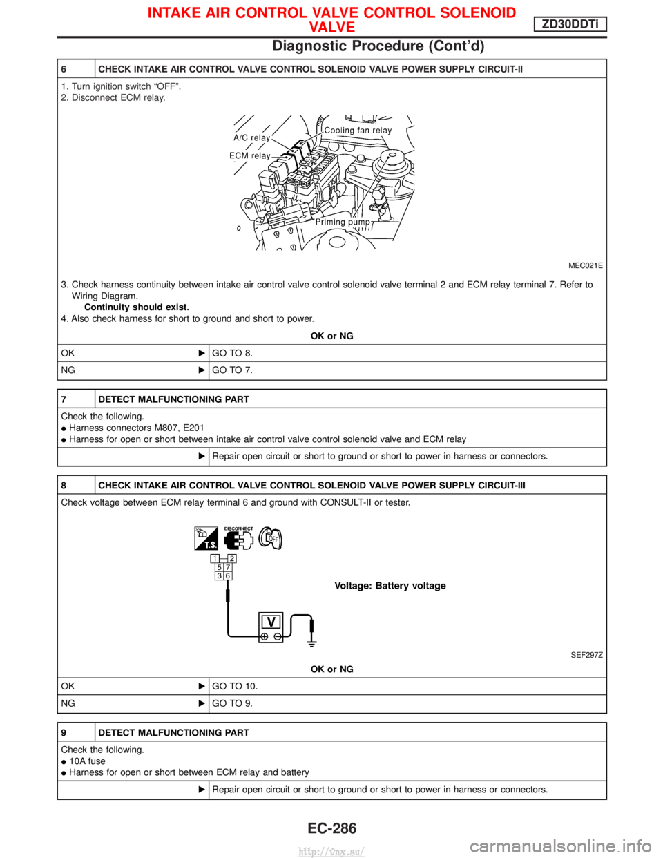
6 CHECK INTAKE AIR CONTROL VALVE CONTROL SOLENOID VALVE POWER SUPPLY CIRCUIT-II
1. Turn ignition switch ªOFFº.
2. Disconnect ECM relay.
MEC021E
3. Check harness continuity between intake air control valve control solenoid valve terminal 2 and ECM relay terminal 7. Refer toWiring Diagram. Continuity should exist.
4. Also check harness for short to ground and short to power.
OK or NG
OK EGO TO 8.
NG EGO TO 7.
7 DETECT MALFUNCTIONING PART
Check the following.
IHarness connectors M807, E201
I Harness for open or short between intake air control valve control solenoid valve and ECM relay
ERepair open circuit or short to ground or short to power in harness or connectors.
8 CHECK INTAKE AIR CONTROL VALVE CONTROL SOLENOID VALVE POWER SUPPLY CIRCUIT-III
Check voltage between ECM relay terminal 6 and ground with CONSULT-II or tester.
SEF297Z
OK or NG
OK EGO TO 10.
NG EGO TO 9.
9 DETECT MALFUNCTIONING PART
Check the following.
I10A fuse
I Harness for open or short between ECM relay and battery
ERepair open circuit or short to ground or short to power in harness or connectors.
INTAKE AIR CONTROL VALVE CONTROL SOLENOID
VA LV EZD30DDTi
Diagnostic Procedure (Cont'd)
EC-286
http://vnx.su/
Page 613 of 1833
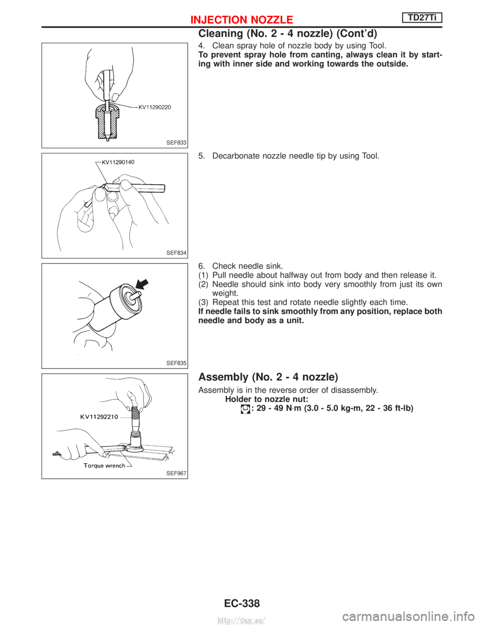
4. Clean spray hole of nozzle body by using Tool.
To prevent spray hole from canting, always clean it by start-
ing with inner side and working towards the outside.
5. Decarbonate nozzle needle tip by using Tool.
6. Check needle sink.
(1) Pull needle about halfway out from body and then release it.
(2) Needle should sink into body very smoothly from just its ownweight.
(3) Repeat this test and rotate needle slightly each time.
If needle fails to sink smoothly from any position, replace both
needle and body as a unit.
Assembly (No.2-4nozzle)
Assembly is in the reverse order of disassembly. Holder to nozzle nut:
:29-49N ×m (3.0 - 5.0 kg-m, 22 - 36 ft-lb)
SEF833
SEF834
SEF835
SEF967
INJECTION NOZZLETD27Ti
Cleaning (No.2-4nozzle) (Cont'd)
EC-338
http://vnx.su/
Page 633 of 1833
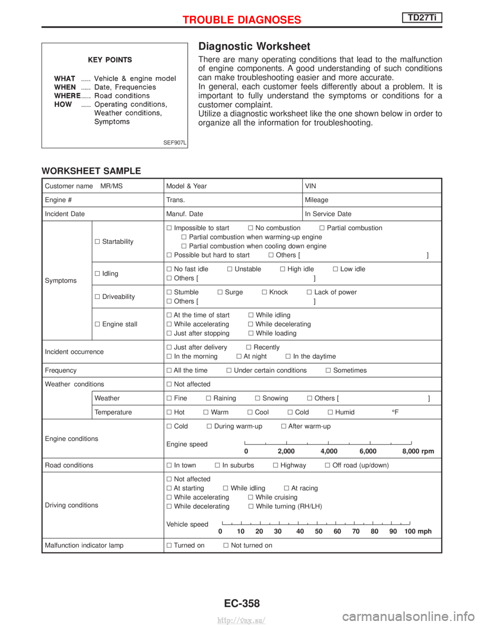
Diagnostic Worksheet
There are many operating conditions that lead to the malfunction
of engine components. A good understanding of such conditions
can make troubleshooting easier and more accurate.
In general, each customer feels differently about a problem. It is
important to fully understand the symptoms or conditions for a
customer complaint.
Utilize a diagnostic worksheet like the one shown below in order to
organize all the information for troubleshooting.
WORKSHEET SAMPLE
Customer name MR/MSModel & Year VIN
Engine # Trans. Mileage
Incident Date Manuf. Date In Service Date
Symptoms l
Startability l
Impossible to start lNo combustion lPartial combustion
l Partial combustion when warming-up engine
l Partial combustion when cooling down engine
l Possible but hard to start lOthers [ ]
l Idling l
No fast idle lUnstable lHigh idle lLow idle
l Others [ ]
l Driveability l
Stumble lSurge lKnock lLack of power
l Others [ ]
l Engine stall l
At the time of start lWhile idling
l While accelerating lWhile decelerating
l Just after stopping lWhile loading
Incident occurrence l
Just after delivery lRecently
l In the morning lAt night lIn the daytime
Frequency lAll the time lUnder certain conditions lSometimes
Weather conditions lNot affected
Weather lFine lRaining lSnowing lOthers [ ]
Temperature lHot lWarm lCool lCold lHumid ÉF
Engine conditions l
Cold lDuring warm-up lAfter warm-up
Engine speed
0 2,000 4,000 6,000 8,000 rpm
Road conditions lIn town lIn suburbs lHighway lOff road (up/down)
Driving conditions l
Not affected
l At starting lWhile idling lAt racing
l While accelerating lWhile cruising
l While decelerating lWhile turning (RH/LH)
Vehicle speed
0 102030 405060708090100mph
Malfunction indicator lamp lTurned on lNot turned on
SEF907L
TROUBLE DIAGNOSESTD27Ti
EC-358
http://vnx.su/
Page 637 of 1833
qA
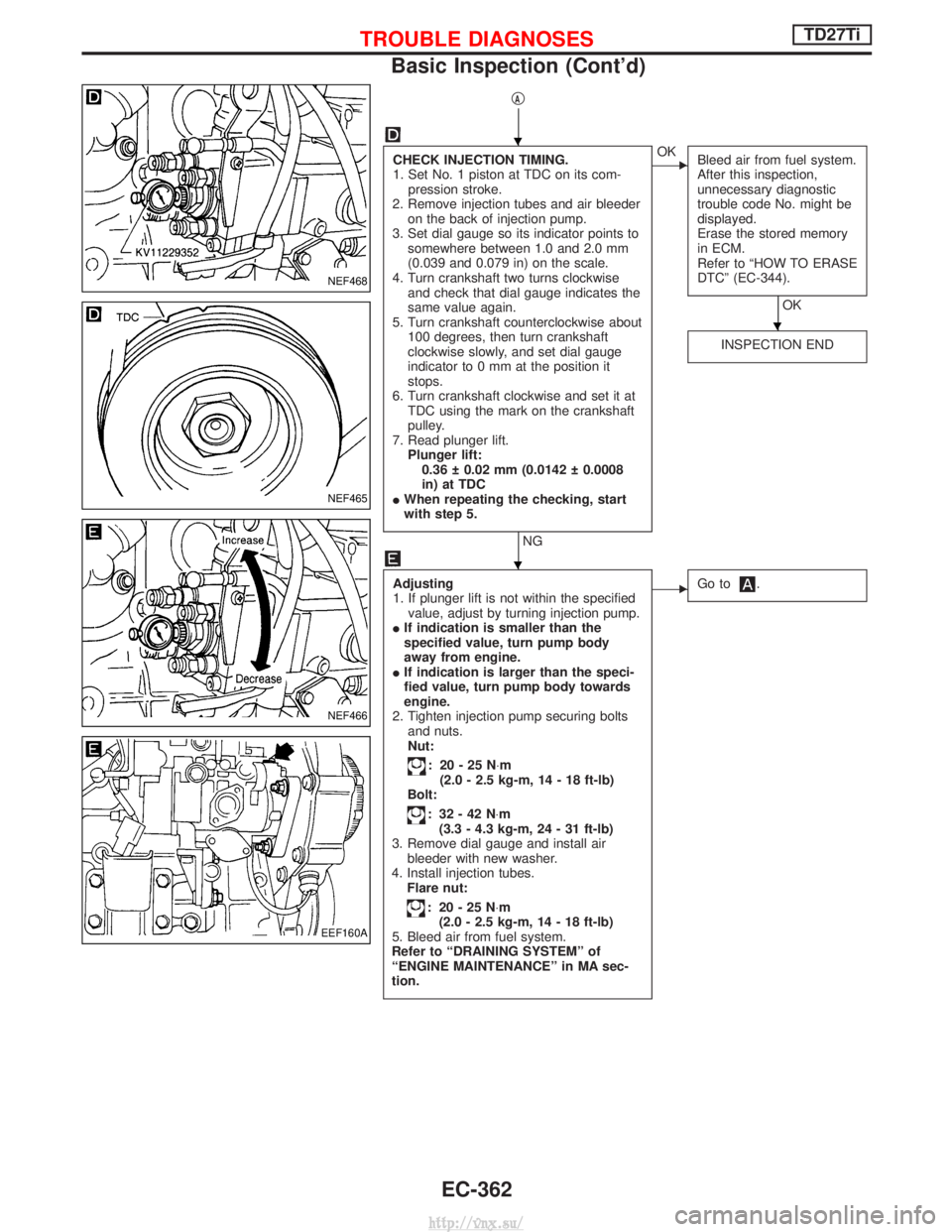
CHECK INJECTION TIMING.
1. Set No. 1 piston at TDC on its com-pression stroke.
2. Remove injection tubes and air bleeder on the back of injection pump.
3. Set dial gauge so its indicator points to somewhere between 1.0 and 2.0 mm
(0.039 and 0.079 in) on the scale.
4. Turn crankshaft two turns clockwise and check that dial gauge indicates the
same value again.
5. Turn crankshaft counterclockwise about 100 degrees, then turn crankshaft
clockwise slowly, and set dial gauge
indicator to 0 mm at the position it
stops.
6. Turn crankshaft clockwise and set it at TDC using the mark on the crankshaft
pulley.
7. Read plunger lift. Plunger lift:0.36 0.02 mm (0.0142 0.0008
in) at TDC
I When repeating the checking, start
with step 5.
NG
EOK
Bleed air from fuel system.
After this inspection,
unnecessary diagnostic
trouble code No. might be
displayed.
Erase the stored memory
in ECM.
Refer to ªHOW TO ERASE
DTCº (EC-344).
OK
INSPECTION END
Adjusting
1. If plunger lift is not within the specified value, adjust by turning injection pump.
I If indication is smaller than the
specified value, turn pump body
away from engine.
I If indication is larger than the speci-
fied value, turn pump body towards
engine.
2. Tighten injection pump securing bolts and nuts.
Nut:
: 20-25N ×m
(2.0 - 2.5 kg-m, 14 - 18 ft-lb)
Bolt:
: 32-42N ×m
(3.3 - 4.3 kg-m, 24 - 31 ft-lb)
3. Remove dial gauge and install air bleeder with new washer.
4. Install injection tubes. Flare nut:
: 20-25N ×m
(2.0 - 2.5 kg-m, 14 - 18 ft-lb)
5. Bleed air from fuel system.
Refer to ªDRAINING SYSTEMº of
ªENGINE MAINTENANCEº in MA sec-
tion.
EGo to.
NEF468
NEF465
NEF466
EEF160A
H
H
H
TROUBLE DIAGNOSESTD27Ti
Basic Inspection (Cont'd)
EC-362
http://vnx.su/
Page 759 of 1833
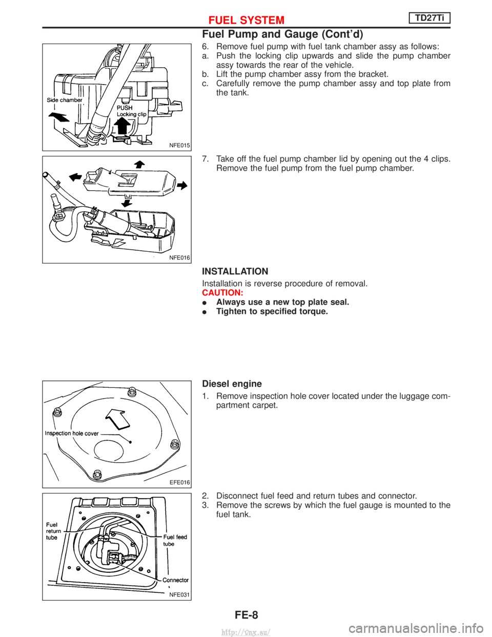
6. Remove fuel pump with fuel tank chamber assy as follows:
a. Push the locking clip upwards and slide the pump chamberassy towards the rear of the vehicle.
b. Lift the pump chamber assy from the bracket.
c. Carefully remove the pump chamber assy and top plate from the tank.
7. Take off the fuel pump chamber lid by opening out the 4 clips. Remove the fuel pump from the fuel pump chamber.
INSTALLATION
Installation is reverse procedure of removal.
CAUTION:
IAlways use a new top plate seal.
I Tighten to specified torque.
Diesel engine
1. Remove inspection hole cover located under the luggage com-
partment carpet.
2. Disconnect fuel feed and return tubes and connector.
3. Remove the screws by which the fuel gauge is mounted to the fuel tank.
NFE015
NFE016
EFE016
NFE031
FUEL SYSTEMTD27Ti
Fuel Pump and Gauge (Cont'd)
FE-8
http://vnx.su/