2004 NISSAN TERRANO tow
[x] Cancel search: towPage 786 of 1833
IRaise the unit with a hoist.
I Position the transmission assembly on a portable jack and
secure it with a suitable tool.
Lift the assembly until the gearbox input shaft faces its hous-
ing.
Move the assembly towards the engine. The assembly must be
rotated slightly so that the starter motor housing clears the
projection on the companion floor. Insert input shaft into its
housing (slightly raising the rear of the transfer box may facili-
tate the introduction of the shaft into its housing).
I Tighten the screws securing the gearbox to the engine.
:39-49N ×m (4.0 - 5.0 kg-m, 29 - 36 ft-lb)
I Connect the electrical wiring. Secure with the respective clips.
I Fit the RPM-sensor to the transmission upper side.
I Fit the exhaust pipe support bracket to the transfer box.
:13-16N ×m (1.3 - 1.6 kg-m ,9-12ft-lb)
I Fit the starter motor. Secure the earth wire to the starter motor
lower screw.
:31-41N ×m (3.2 - 4.2 kg-m, 23 - 30 ft-lb)
I Fit the clutch slave cylinder.
:30-40N ×m (3.1 - 4.1 kg-m, 22 - 30 ft-lb)
I Install fourth crossmember (Note the ªfrontº mark).
Crossmember fixing bolts to chassis:
:41-52N ×m (4.2 - 5.3 kg-m, 30 - 38 ft-lb)
Crossmember fixing bolts to transmission:
:68-87N ×m (6.9 - 8.9 kg-m, 50 - 64 ft-lb)
I Take away the portable jack holding boxes assembly.
I Install fifth crossmember.
:59-78N ×m (6.0 - 8.0 kg-m, 43 - 58 ft-lb)
I Install third crossmember.
: Screws: 41 - 52 N ×m (4.2 - 5.3 kg-m,
30 - 38 ft-lb)
Nuts: 68 - 87 N ×m (6.9 - 8.9 kg-m,
50 - 64 ft-lb)
I Install torsion bar springs. Ð Refer to FA section.
I Install front and rear propeller shafts. Ð Refer to PD section.
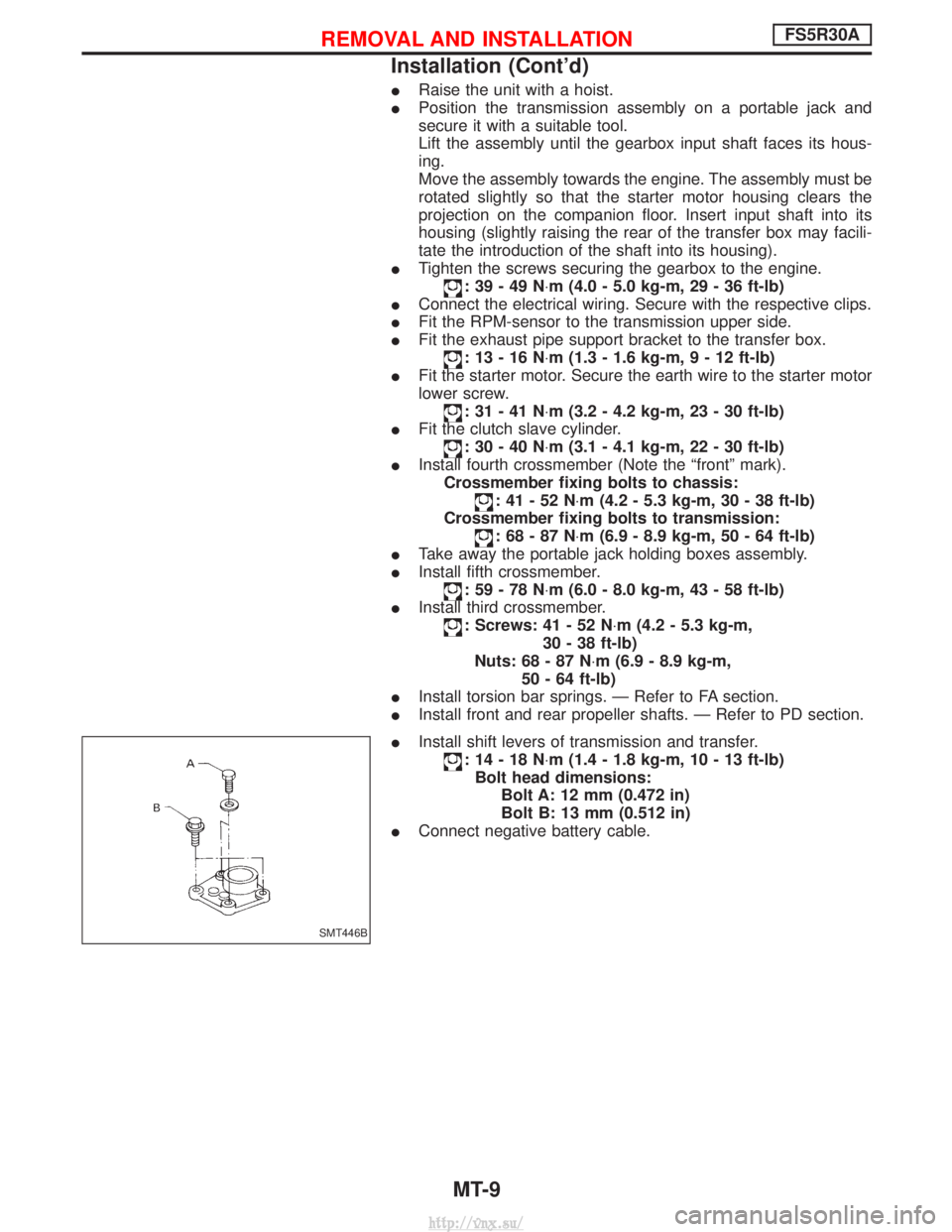
I Install shift levers of transmission and transfer.
:14-18N ×m (1.4 - 1.8 kg-m, 10 - 13 ft-lb)
Bolt head dimensions: Bolt A: 12 mm (0.472 in)
Bolt B: 13 mm (0.512 in)
I Connect negative battery cable.
SMT446B
REMOVAL AND INSTALLATIONFS5R30A
Installation (Cont'd)
MT-9
http://vnx.su/
Page 817 of 1833
Supplemental Restraint System (SRS) ªAIR
BAGº and ªSEAT BELT PRE-TENSIONERº
The Supplemental Restraint System such as ªAIR BAGº and ªSEAT BELT PRE-TENSIONERº used along with
a seat belt, helps to reduce the risk or severity of injury to the driver and front passenger for certain types of
collision. The SRS composition which is available to NISSAN MODEL R20 is as follows (The composition
varies according to the destination and optional equipment.):
IFor a frontal collision
The Supplemental Restraint System consists of driver air bag module (located in the center of the steer-
ing wheel), front passenger air bag module (located on the instrument panel on passenger side), front seat
belt pre-tensioners, a diagnosis sensor unit, warning lamp, wiring harness and spiral cable.
I For a side collision
The Supplemental Restraint System consists of front side air bag module (located in the outer side of front
seat), side air bag (satellite) sensor, diagnosis sensor unit (one of components of air bags for a frontal
collision), wiring harness, warning lamp (one of components of air bags for a frontal collision).
WARNING:
I To avoid rendering the SRS inoperative, which could increase the risk of personal injury or death
in the event of a collision which would result in air bag inflation, all maintenance should be per-
formed by an authorized NISSAN dealer.
I Improper maintenance, including incorrect removal and installation of the SRS, can lead to per-
sonal injury caused by unintentional activation of the system.
I Do not use electrical test equipment on any circuit related to the SRS unless instructed to in this
Service Manual. Spiral cable and wiring harnesses covered with yellow insulation tape either just
before the harness connectors or for the complete harness are related to the SRS.
Precautions for SRS ªAIR BAGº and ªSEAT
BELT PRE-TENSIONERº Service
IDo not use electrical test equipment to check SRS circuits unless instructed to in this Service Manual.
I Before servicing the SRS, turn ignition switch ªOFFº, disconnect both battery cables and wait at least 3
minutes.
For approximately 3 minutes after the cables are removed, it is still possible for the air bag and seat belt
pre-tensioner to deploy. Therefore, do not work on any SRS connectors or wires until at least 3 minutes
have passed.
I Diagnosis sensor unit must always be installed with their arrow marks ª +º pointing towards the front of
the vehicle for proper operation. Also check diagnosis sensor unit for cracks, deformities or rust before
installation and replace as required.
I The spiral cable must be aligned with the neutral position since its rotations are limited. Do not attempt to
turn steering wheel or column after removal of steering gear.
I Handle air bag module carefully. Always place driver and front passenger air bag modules with the pad
side facing upward and place front side air bag module (built-in type) standing with stud bolt side setting
bottom.
I Conduct self-diagnosis to check entire SRS for proper function after replacing any components.
I After air bag inflates, the front instrument panel assembly should be replaced if damaged.
Precautions
IBefore proceeding with disassembly, thoroughly clean the outside of the transmission. It is important to
prevent the internal parts from becoming contaminated by dirt or other foreign matter.
I Disassembly should be done in a clean work area.
I Use lint-free cloth or towels for wiping parts clean. Common shop rags can leave fibers that could inter-
fere with the operation of the transmission.
I Place disassembled parts in order for easier and proper assembly.
I All parts should be carefully cleaned with a general purpose, non-flammable solvent before inspection or
reassembly.
I Gaskets, seals and O-rings should be replaced any time the transmission is disassembled.
I It is very important to perform functional tests whenever they are indicated.
I The valve body contains precision parts and requires extreme care when parts are removed and serviced.
Place removed parts in a parts rack in order to replace them in correct positions and sequences. Care will
also prevent springs and small parts from becoming scattered or lost.
I Properly installed valves, sleeves, plugs, etc. will slide along bores in valve body under their own weight.
PREPARATION AND PRECAUTIONS
AT- 4
http://vnx.su/
Page 933 of 1833
Manual Control Linkage Adjustment
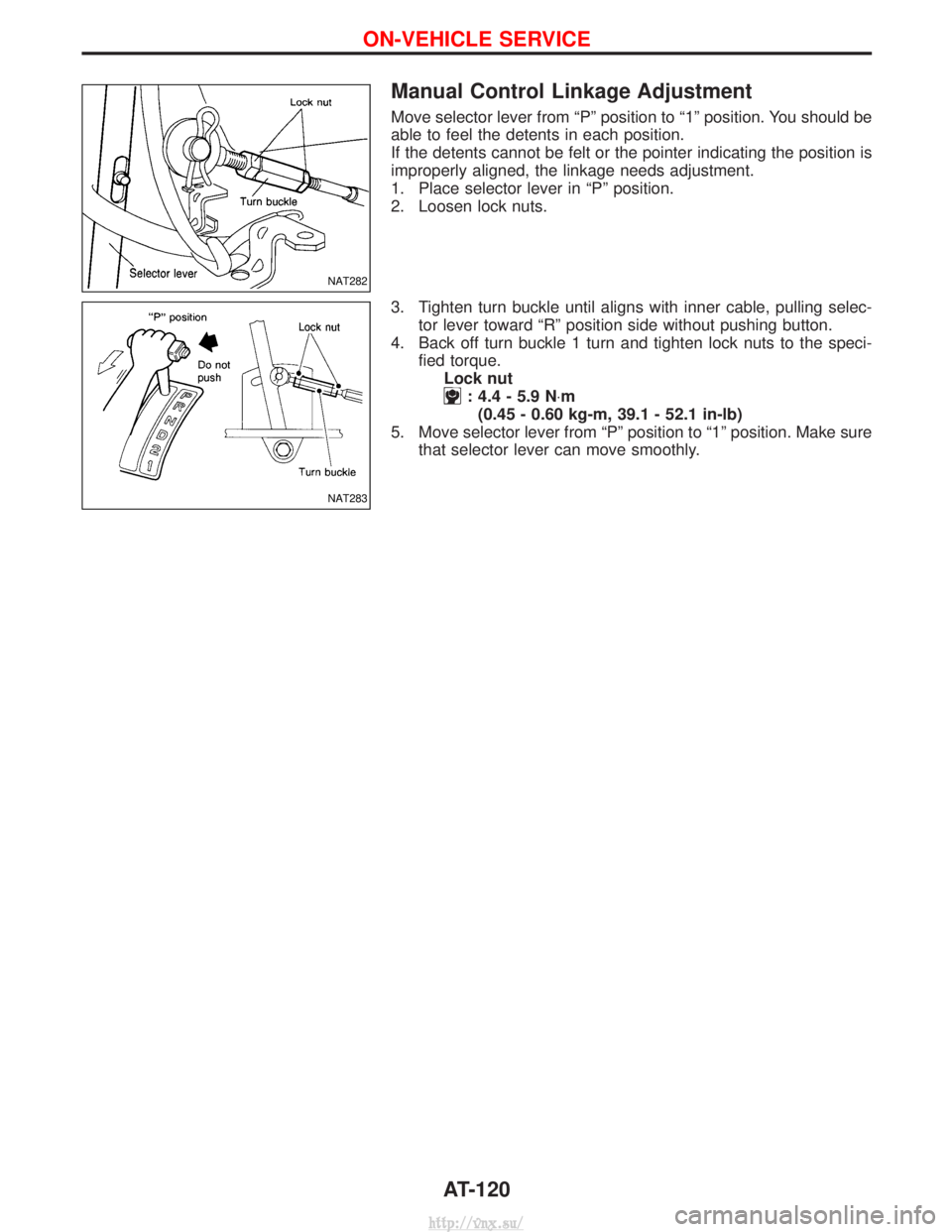
Move selector lever from ªPº position to ª1º position. You should be
able to feel the detents in each position.
If the detents cannot be felt or the pointer indicating the position is
improperly aligned, the linkage needs adjustment.
1. Place selector lever in ªPº position.
2. Loosen lock nuts.
3. Tighten turn buckle until aligns with inner cable, pulling selec-tor lever toward ªRº position side without pushing button.
4. Back off turn buckle 1 turn and tighten lock nuts to the speci- fied torque.Lock nut
: 4.4 - 5.9 N ×m
(0.45 - 0.60 kg-m, 39.1 - 52.1 in-lb)
5. Move selector lever from ªPº position to ª1º position. Make sure that selector lever can move smoothly.
NAT282
NAT283
ON-VEHICLE SERVICE
AT-120
http://vnx.su/
Page 954 of 1833
Side clearances
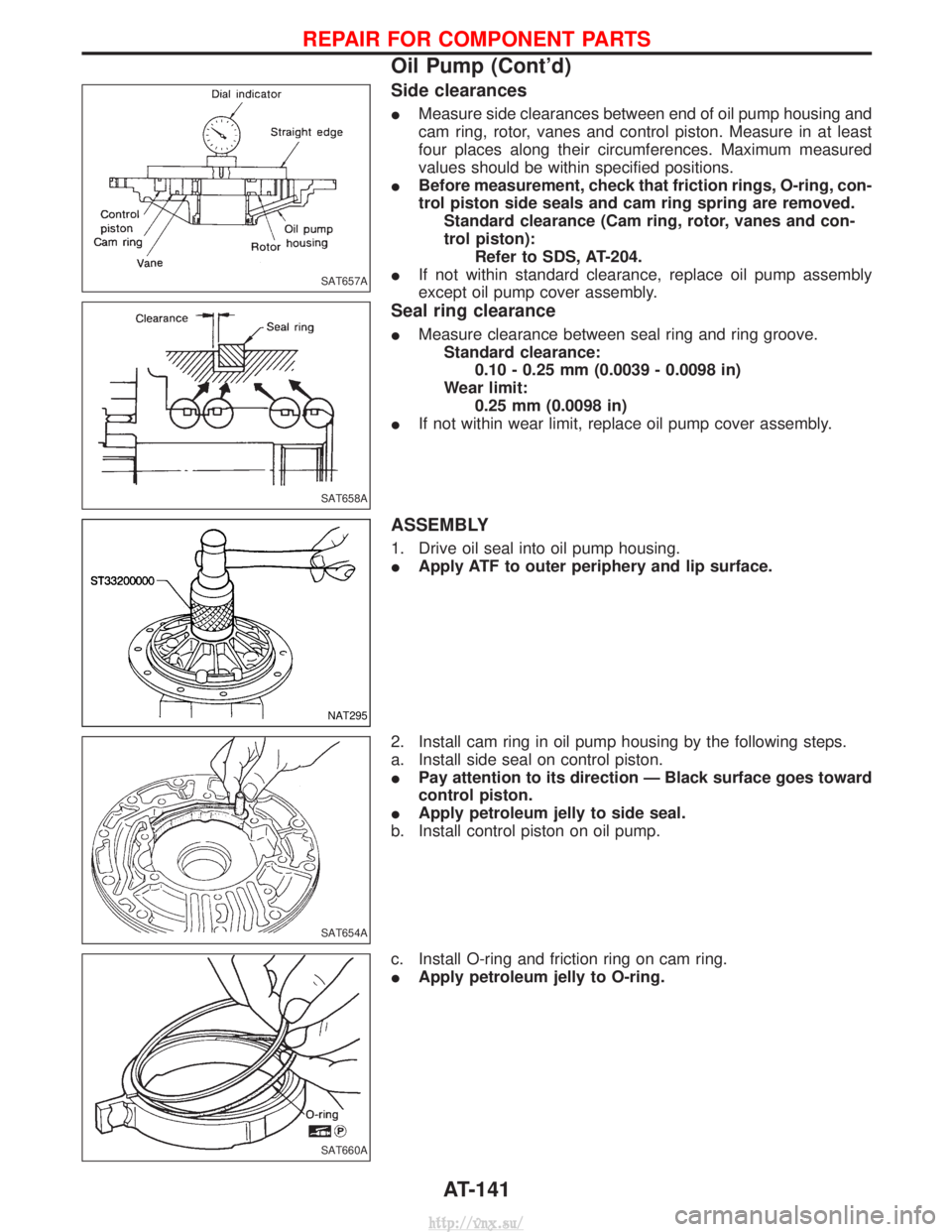
IMeasure side clearances between end of oil pump housing and
cam ring, rotor, vanes and control piston. Measure in at least
four places along their circumferences. Maximum measured
values should be within specified positions.
I Before measurement, check that friction rings, O-ring, con-
trol piston side seals and cam ring spring are removed.
Standard clearance (Cam ring, rotor, vanes and con-
trol piston): Refer to SDS, AT-204.
I If not within standard clearance, replace oil pump assembly
except oil pump cover assembly.
Seal ring clearance
IMeasure clearance between seal ring and ring groove.
Standard clearance: 0.10 - 0.25 mm (0.0039 - 0.0098 in)
Wear limit: 0.25 mm (0.0098 in)
I If not within wear limit, replace oil pump cover assembly.
ASSEMBLY
1. Drive oil seal into oil pump housing.
IApply ATF to outer periphery and lip surface.
2. Install cam ring in oil pump housing by the following steps.
a. Install side seal on control piston.
I Pay attention to its direction Ð Black surface goes toward
control piston.
I Apply petroleum jelly to side seal.
b. Install control piston on oil pump.
c. Install O-ring and friction ring on cam ring.
I Apply petroleum jelly to O-ring.
SAT657A
SAT658A
NAT295
SAT654A
SAT660A
REPAIR FOR COMPONENT PARTS
Oil Pump (Cont'd)
AT-141
http://vnx.su/
Page 1120 of 1833
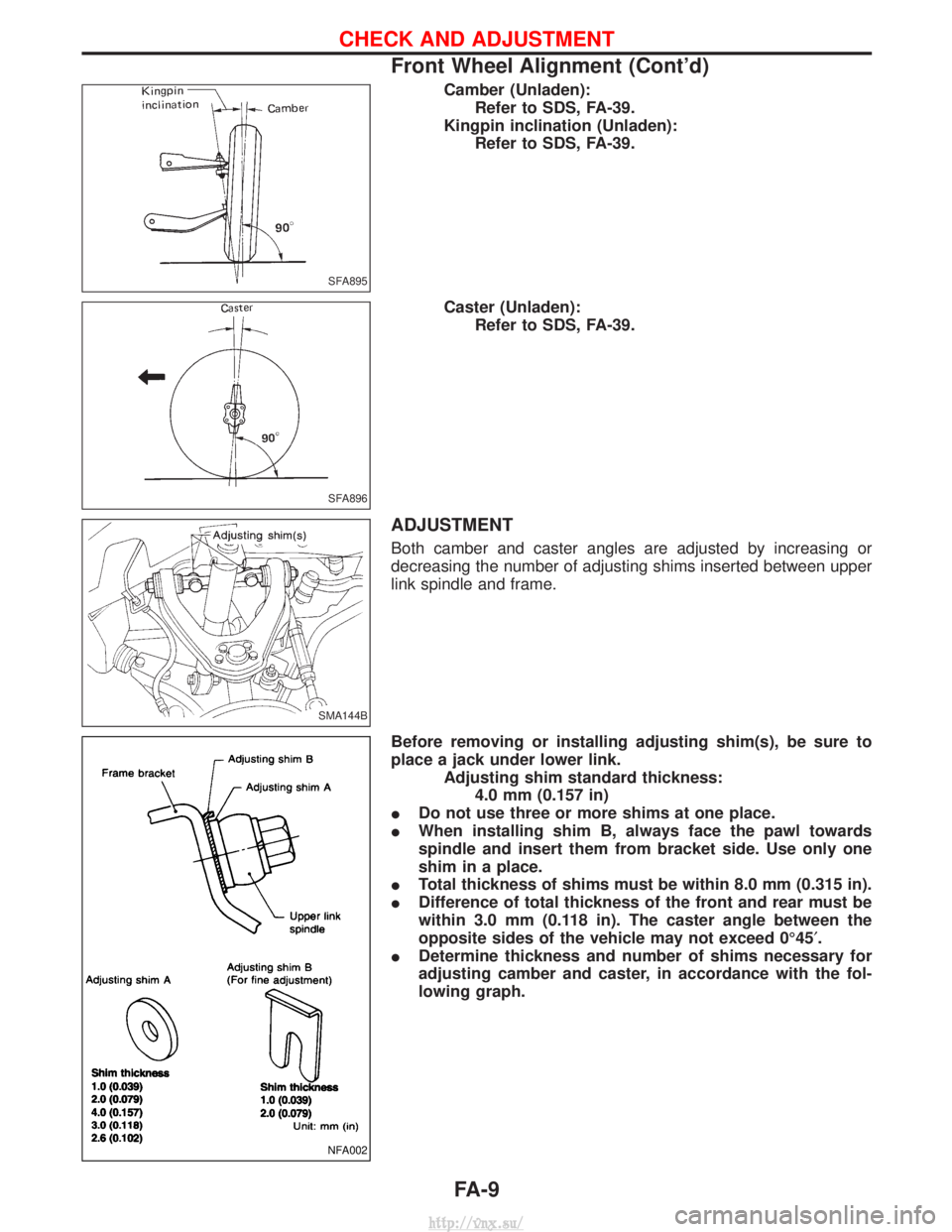
Camber (Unladen):Refer to SDS, FA-39.
Kingpin inclination (Unladen): Refer to SDS, FA-39.
Caster (Unladen): Refer to SDS, FA-39.
ADJUSTMENT
Both camber and caster angles are adjusted by increasing or
decreasing the number of adjusting shims inserted between upper
link spindle and frame.
Before removing or installing adjusting shim(s), be sure to
place a jack under lower link. Adjusting shim standard thickness:4.0 mm (0.157 in)
I Do not use three or more shims at one place.
I When installing shim B, always face the pawl towards
spindle and insert them from bracket side. Use only one
shim in a place.
I Total thickness of shims must be within 8.0 mm (0.315 in).
I Difference of total thickness of the front and rear must be
within 3.0 mm (0.118 in). The caster angle between the
opposite sides of the vehicle may not exceed 0É45 ¢.
I Determine thickness and number of shims necessary for
adjusting camber and caster, in accordance with the fol-
lowing graph.
SFA895
SFA896
SMA144B
NFA002
CHECK AND ADJUSTMENT
Front Wheel Alignment (Cont'd)
FA-9
http://vnx.su/
Page 1135 of 1833
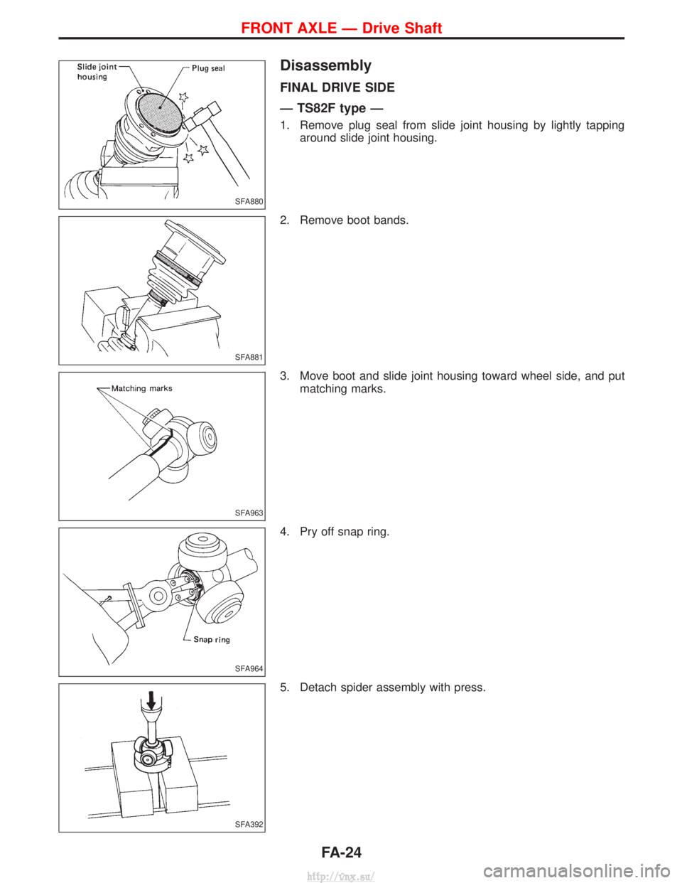
Disassembly
FINAL DRIVE SIDE
Ð TS82F type Ð
1. Remove plug seal from slide joint housing by lightly tappingaround slide joint housing.
2. Remove boot bands.
3. Move boot and slide joint housing toward wheel side, and put matching marks.
4. Pry off snap ring.
5. Detach spider assembly with press.
SFA880
SFA881
SFA963
SFA964
SFA392
FRONT AXLE Ð Drive Shaft
FA-24
http://vnx.su/
Page 1255 of 1833
Supplemental Restraint System (SRS) ªAIR
BAGº and ªSEAT BELT PRE-TENSIONERº
The Supplemental Restraint System such as ªAIR BAGº and ªSEAT BELT PRE-TENSIONERº used along with
a seat belt, helps to reduce the risk or severity of injury to the driver and front passenger for certain types of
collision. The SRS composition which is available to NISSAN MODEL R20 is as follows (The composition
varies according to the destination and optional equipment.):
IFor a frontal collision
The Supplemental Restraint System consists of driver air bag module (located in the center of the steer-
ing wheel), front passenger air bag module (located on the instrument panel on passenger side), front seat
belt pre-tensioners, a diagnosis sensor unit, warning lamp, wiring harness and spiral cable.
I For a side collision
The Supplemental Restraint System consists of front side air bag module (located in the outer side of front
seat), side air bag (satellite) sensor, diagnosis sensor unit (one of components of air bags for a frontal
collision), wiring harness, warning lamp (one of components of air bags for a frontal collision).
WARNING:
I To avoid rendering the SRS inoperative, which could increase the risk of personal injury or death
in the event of a collision which would result in air bag inflation, all maintenance should be per-
formed by an authorized NISSAN dealer.
I Improper maintenance, including incorrect removal and installation of the SRS, can lead to per-
sonal injury caused by unintentional activation of the system.
I Do not use electrical test equipment on any circuit related to the SRS unless instructed to in this
Service Manual. Spiral cable and wiring harnesses covered with yellow insulation tape either just
before the harness connectors or for the complete harness are related to the SRS.
Precautions for SRS ªAIR BAGº and ªSEAT
BELT PRE-TENSIONERº Service
IDo not use electrical test equipment to check SRS circuits unless instructed to in this Service Manual.
I Before servicing the SRS, turn ignition switch ªOFFº, disconnect both battery cables and wait at least 3
minutes.
For approximately 3 minutes after the cables are removed, it is still possible for the air bag and seat belt
pre-tensioner to deploy. Therefore, do not work on any SRS connectors or wires until at least 3 minutes
have passed.
I Diagnosis sensor unit must always be installed with their arrow marks ª +º pointing towards the front of
the vehicle for proper operation. Also check diagnosis sensor unit for cracks, deformities or rust before
installation and replace as required.
I The spiral cable must be aligned with the neutral position since its rotations are limited. Do not attempt to
turn steering wheel or column after removal of steering gear.
I Handle air bag module carefully. Always place driver and front passenger air bag modules with the pad
side facing upward and place front side air bag module (built-in type) standing with stud bolt side setting
bottom.
I Conduct self-diagnosis to check entire SRS for proper function after replacing any components.
I After air bag inflates, the front instrument panel assembly should be replaced if damaged.
Precautions for Steering System
IBefore disassembly, thoroughly clean the outside of the unit.
I Disassembly should be done in a clean work area. It is important to prevent the internal parts from
becoming contaminated by dirt or other foreign matter.
I When disassembling parts, be sure to place them in order on a part rack so they can be reinstalled
in their proper positions.
I Use nylon cloths or paper towels to clean the parts; common shop rags can leave lint that might
interfere with their operation.
I Before inspection or reassembly, carefully clean all parts with a general purpose, non-flammable
solvent.
I Before assembly, apply a coat of recommended ATF* to hydraulic parts. Vaseline may be applied
to O-rings and seals. Do not use any grease.
I Replace all gaskets, seals and O-rings. Avoid damaging O-rings, seals and gaskets during instal-
lation. Perform functional tests whenever designated.
*: Automatic transmission fluid
PRECAUTIONS
ST-2
http://vnx.su/
Page 1264 of 1833
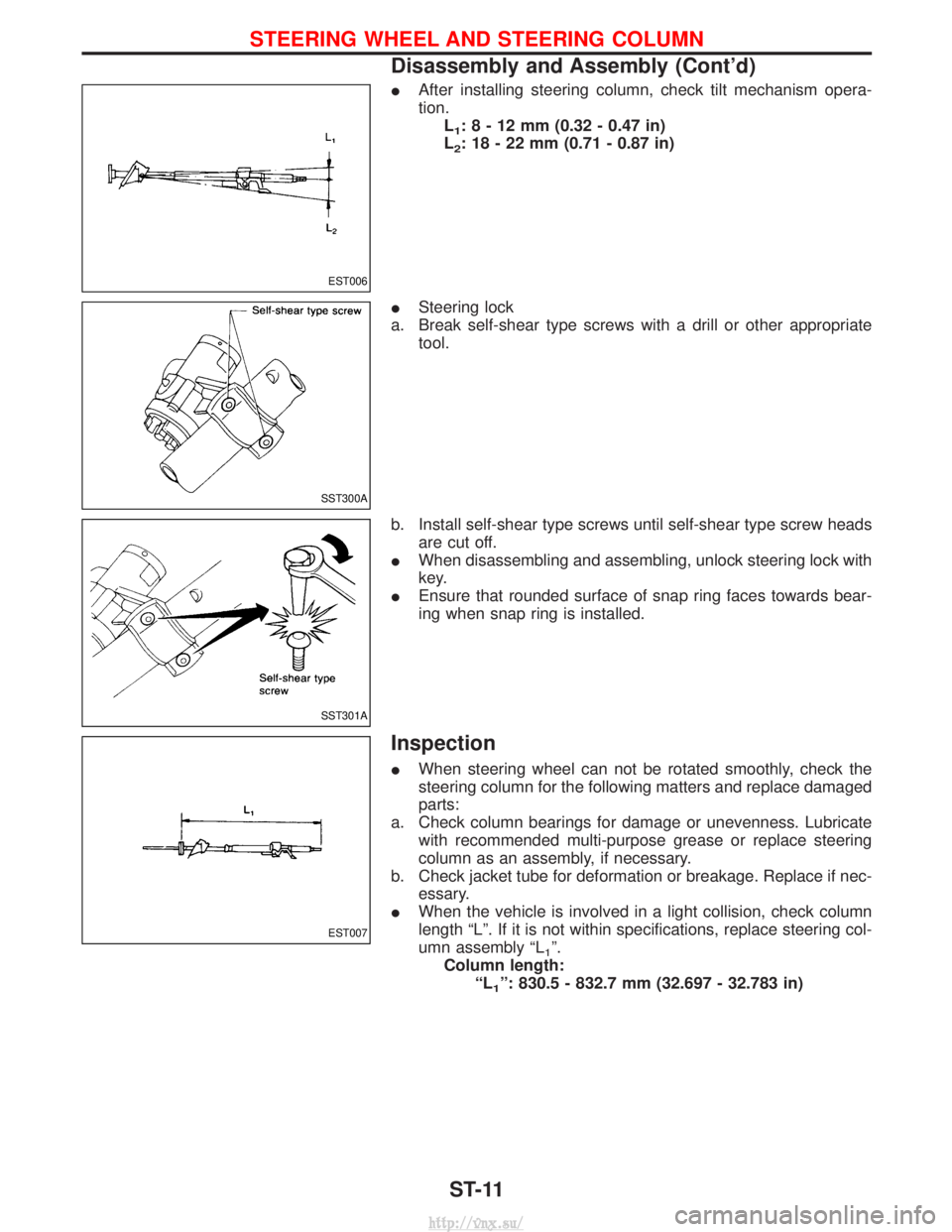
IAfter installing steering column, check tilt mechanism opera-
tion.
L
1:8-12mm (0.32 - 0.47 in)
L
2: 18 - 22 mm (0.71 - 0.87 in)
I Steering lock
a. Break self-shear type screws with a drill or other appropriate tool.
b. Install self-shear type screws until self-shear type screw heads are cut off.
I When disassembling and assembling, unlock steering lock with
key.
I Ensure that rounded surface of snap ring faces towards bear-
ing when snap ring is installed.
Inspection
IWhen steering wheel can not be rotated smoothly, check the
steering column for the following matters and replace damaged
parts:
a. Check column bearings for damage or unevenness. Lubricate with recommended multi-purpose grease or replace steering
column as an assembly, if necessary.
b. Check jacket tube for deformation or breakage. Replace if nec- essary.
I When the vehicle is involved in a light collision, check column
length ªLº. If it is not within specifications, replace steering col-
umn assembly ªL
1º.
Column length: ªL
1º: 830.5 - 832.7 mm (32.697 - 32.783 in)
EST006
SST300A
SST301A
EST007
STEERING WHEEL AND STEERING COLUMN
Disassembly and Assembly (Cont'd)
ST-11
http://vnx.su/