2004 NISSAN TERRANO Speed sensor ring
[x] Cancel search: Speed sensor ringPage 276 of 1833
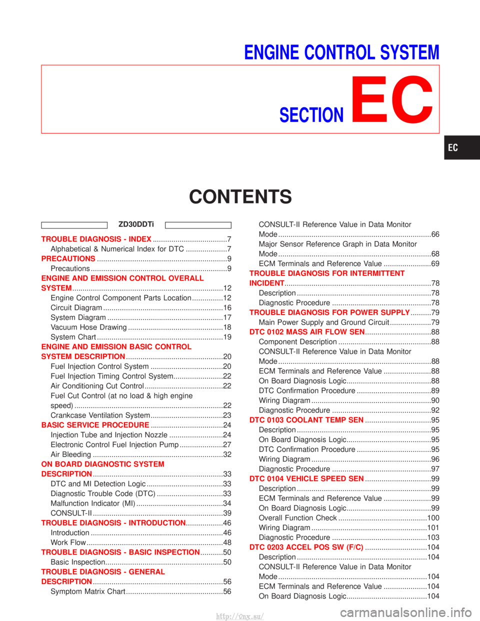
ENGINE CONTROL SYSTEMSECTION
EC
CONTENTS
ZD30DDTi
TROUBLE DIAGNOSIS - INDEX ....................................7
Alphabetical & Numerical Index for DTC ....................7
PRECAUTIONS ...............................................................9
Precautions ..................................................................9
ENGINE AND EMISSION CONTROL OVERALL
SYSTEM ........................................................................\
.12
Engine Control Component Parts Location ...............12
Circuit Diagram ..........................................................16
System Diagram ........................................................17
Vacuum Hose Drawing ..............................................18
System Chart .............................................................19
ENGINE AND EMISSION BASIC CONTROL
SYSTEM DESCRIPTION ...............................................20
Fuel Injection Control System ...................................20
Fuel Injection Timing Control System........................22
Air Conditioning Cut Control ......................................22
Fuel Cut Control (at no load & high engine
speed) ........................................................................\
22
Crankcase Ventilation System ...................................23
BASIC SERVICE PROCEDURE ...................................24
Injection Tube and Injection Nozzle ..........................24
Electronic Control Fuel Injection Pump .....................27
Air Bleeding ...............................................................32
ON BOARD DIAGNOSTIC SYSTEM
DESCRIPTION ...............................................................33
DTC and MI Detection Logic .....................................33
Diagnostic Trouble Code (DTC) ................................33
Malfunction Indicator (MI) ..........................................34
CONSULT-II ...............................................................39
TROUBLE DIAGNOSIS - INTRODUCTION ..................46
Introduction ................................................................46
Work Flow ..................................................................48
TROUBLE DIAGNOSIS - BASIC INSPECTION ...........50
Basic Inspection.........................................................50
TROUBLE DIAGNOSIS - GENERAL
DESCRIPTION ...............................................................56
Symptom Matrix Chart ...............................................56 CONSULT-II Reference Value in Data Monitor
Mode ........................................................................\
..66
Major Sensor Reference Graph in Data Monitor
Mode ........................................................................\
..68
ECM Terminals and Reference Value .......................69
TROUBLE DIAGNOSIS FOR INTERMITTENT
INCIDENT .......................................................................78
Description .................................................................78
Diagnostic Procedure ................................................78
TROUBLE DIAGNOSIS FOR POWER SUPPLY ..........79
Main Power Supply and Ground Circuit ....................79
DTC 0102 MASS AIR FLOW SEN ................................88
Component Description .............................................88
CONSULT-II Reference Value in Data Monitor
Mode ........................................................................\
..88
ECM Terminals and Reference Value .......................88
On Board Diagnosis Logic.........................................88
DTC Confirmation Procedure ....................................89
Wiring Diagram ..........................................................90
Diagnostic Procedure ................................................92
DTC 0103 COOLANT TEMP SEN ................................95
Description .................................................................95
On Board Diagnosis Logic.........................................95
DTC Confirmation Procedure ....................................95
Wiring Diagram ..........................................................96
Diagnostic Procedure ................................................97
DTC 0104 VEHICLE SPEED SEN ................................99
Description .................................................................99
ECM Terminals and Reference Value .......................99
On Board Diagnosis Logic.........................................99
Overall Function Check ...........................................100
Wiring Diagram ........................................................101
Diagnostic Procedure ..............................................103
DTC 0203 ACCEL POS SW (F/C) ..............................104
Description ...............................................................104
CONSULT-II Reference Value in Data Monitor
Mode ........................................................................\
104
ECM Terminals and Reference Value .....................104
On Board Diagnosis Logic.......................................104
http://vnx.su/
Page 279 of 1833
Diagnostic Procedure ..............................................292
ENGINE OIL PRESSURE SWITCH ............................297
Component Description ...........................................297
System Description ..................................................297
ECM Terminals and Reference Value .....................298
Wiring Diagram ........................................................299
Diagnostic Procedure ..............................................301
AIR CONDITIONER CONTROL ..................................308
Wiring Diagram ........................................................308
MI (MIL) & DATA LINK CONNECTORS .....................310
Wiring Diagram ........................................................310
SERVICE DATA AND SPECIFICATIONS (SDS) ........312
General Specifications .............................................312
Injection Pump Numbers .........................................312
Injection Nozzle .......................................................312
Engine Coolant Temperature Sensor ......................312
Crankshaft Position Sensor (TDC) ..........................312
Glow Plug ................................................................312
Accelerator Position Sensor ....................................312
EGR Volume Control Valve .....................................312
TD27Ti
TROUBLE DIAGNOSIS - INDEX ................................313
Alphabetical & Numerical Index for DTC ................313
PRECAUTIONS AND PREPARATION ........................315
Precautions ..............................................................315
Special Service Tools ..............................................318
Engine Fuel & Emission Control System ................320
ENGINE AND EMISSION CONTROL OVERALL
SYSTEM .......................................................................323
Engine Control Component Parts Location .............323
Circuit Diagram ........................................................325
System Diagram ......................................................326
Vacuum Hose Drawing ............................................327
System Chart ...........................................................328
ENGINE AND EMISSION BASIC CONTROL
SYSTEM DESCRIPTION .............................................329
Fuel Injection System ..............................................329
Fuel Injection Timing System ..................................332
Air Conditioning Cut Control ....................................334
Fuel Cut Control (at high engine speed) .................334
Glow Control ............................................................334
CRANKCASE VENTILATION SYSTEM ......................335
Description ...............................................................335
Blow-by Control Valve .............................................335
Ventilation Hose .......................................................335
INJECTION NOZZLE ...................................................336
Removal and Installation .........................................336
Disassembly (No.2-4 nozzle) ...............................336
Inspection (No.2-4 nozzle) ...................................337
Cleaning (No.2-4 nozzle) .....................................337
Assembly (No.2-4 nozzle) ....................................338 Test and Adjustment ................................................339
ELECTRONIC FUEL INJECTION PUMP ....................341
Removal ...................................................................341
Installation ................................................................342
Disassembly and Assembly .....................................343
ON BOARD DIAGNOSTIC SYSTEM
DESCRIPTION .............................................................344
DTC and MI Detection Logic ...................................344
Diagnostic Trouble Code (DTC) ..............................344
Malfunction Indicator (MI) ........................................345
CONSULT-II .............................................................350
TROUBLE DIAGNOSES .............................................357
Introduction ..............................................................357
Diagnostic Worksheet ..............................................358
Work Flow ................................................................359
Description for Work Flow .......................................360
Basic Inspection.......................................................361
Symptom Matrix Chart .............................................363
CONSULT-II Reference Value in Data Monitor
Mode ........................................................................\
366
Major Sensor Reference Graph in Data Monitor
Mode ........................................................................\
368
ECM Terminals and Reference Value .....................369
TROUBLE DIAGNOSIS FOR POWER SUPPLY ........375
Wiring Diagram ........................................................375
Diagnostic Procedure ..............................................376
DTC P0100 MASS AIR FLOW SEN ...........................379
Component Description ...........................................379
On Board Diagnosis Logic.......................................379
DTC Confirmation Procedure ..................................379
Wiring Diagram ........................................................380
Diagnostic Procedure ..............................................382
Component Inspection .............................................383
DTC P0115 COOLANT TEMP SEN ............................384
Component Description ...........................................384
On Board Diagnosis Logic.......................................384
DTC Confirmation Procedure ..................................384
Wiring Diagram ........................................................385
Diagnostic Procedure ..............................................386
Component Inspection .............................................387
DTC P0120 ACCEL POS SENSOR ............................388
Component Description ...........................................388
On Board Diagnosis Logic.......................................388
DTC Confirmation Procedure A (For General
Plausibility) ...............................................................388
DTC Confirmation Procedure B (For Accelerator
Sticking) ...................................................................389
Wiring Diagram ........................................................390
Diagnostic Procedure ..............................................391
Component Inspection .............................................394
DTC P0180 FUEL TEMP SENSOR ............................395
Component Description ...........................................395
CONTENTS(Cont'd)
EC-4
http://vnx.su/
Page 296 of 1833

Normal control
Input/output signal chart
SensorInput Signal to ECM ECM Function Actuator
Crankshaft position sensor (TDC) Engine speed
Fuel injection con-
trol (Normal con-
trol)Electronic control fuel injec-
tion pump
Accelerator position sensor
Accelerator position
Vehicle speed sensor Vehicle speed
The amount of fuel injected under normal driving conditions is
determined according to sensor signals. The crankshaft position
sensor (TDC) detects engine speed and the accelerator position
sensor detects accelerator position. These sensors send signals to
the ECM.
The fuel injection data, predetermined by correlation between vari-
ous engine speeds and accelerator positions, are stored in the
ECM memory, forming a map. The ECM determines the optimal
amount of fuel to be injected using the sensor signals in compari-
son with the map.
Maximum amount control
Input/output signal chart
SensorInput Signal to ECM ECM Function Actuator
Mass air flow sensor Amount of intake air
Fuel injection con-
trol (Maximum
amount control)Electronic control fuel injec-
tion pump
Engine coolant temperature sensor Engine coolant temperature
Crankshaft position sensor (TDC) Engine speed
Accelerator position sensor Accelerator position
The maximum injection amount is controlled to an optimum by the engine speed, intake air amount, engine
coolant temperature, and accelerator opening in accordance with the driving conditions.
This prevents the oversupply of the injection amount caused by decreased air density at a high altitude or
during a system failure.
Deceleration control
Input/output signal chart
Sensor
Input Signal to ECM ECM Function Actuator
Accelerator switch (F/C) Accelerator positionFuel injection con-
trol (Deceleration
control)Electronic control fuel injec-
tion pump
Crankshaft position sensor (TDC) Engine speed
The ECM sends a fuel cut signal to the electronic control fuel injection pump during deceleration for better
fuel efficiency. The ECM determines the time of deceleration according to signals from the accelerator switch
(F/C) and crankshaft position sensor (TDC).
SEF649S
ENGINE AND EMISSION BASIC CONTROL SYSTEM
DESCRIPTIONZD30DDTi
Fuel Injection Control System (Cont'd)
EC-21
http://vnx.su/
Page 333 of 1833
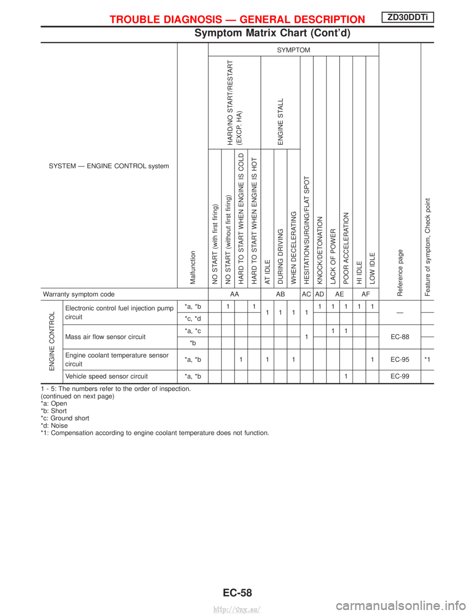
SYSTEM Ð ENGINE CONTROL system
Malfunction
SYMPTOM
Reference page
Feature of symptom, Check pointHARD/NO START/RESTART
(EXCP. HA)
ENGINE STALL
HESITATION/SURGING/FLAT SPOT
KNOCK/DETONATION
LACK OF POWER
POOR ACCELERATION
HI IDLE
LOW IDLE NO START (with first firing)
NO START (without first firing)
HARD TO START WHEN ENGINE IS COLD
HARD TO START WHEN ENGINE IS HOT
AT IDLE
DURING DRIVING
WHEN DECELERATINGWarranty symptom code AAAB AC AD AE AF
ENGINE CONTROL
Electronic control fuel injection pump
circuit *a, *b 1 1
111111111
Ð
*c, *d
Mass air flow sensor circuit *a, *c
111
EC-88
*b
Engine coolant temperature sensor
circuit *a, *b 1 1 1 1 EC-95 *1
Vehicle speed sensor circuit *a, *b 1 EC-99
1 - 5: The numbers refer to the order of inspection.
(continued on next page)
*a: Open
*b: Short
*c: Ground short
*d: Noise
*1: Compensation according to engine coolant temperature does not function.
TROUBLE DIAGNOSIS Ð GENERAL DESCRIPTIONZD30DDTi
Symptom Matrix Chart (Cont'd)
EC-58
http://vnx.su/
Page 363 of 1833
Component Description
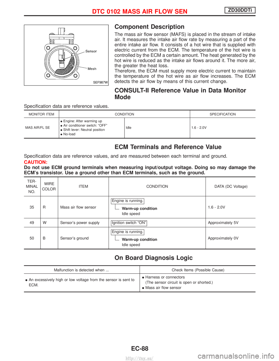
The mass air flow sensor (MAFS) is placed in the stream of intake
air. It measures the intake air flow rate by measuring a part of the
entire intake air flow. It consists of a hot wire that is supplied with
electric current from the ECM. The temperature of the hot wire is
controlled by the ECM a certain amount. The heat generated by the
hot wire is reduced as the intake air flows around it. The more air,
the greater the heat loss.
Therefore, the ECM must supply more electric current to maintain
the temperature of the hot wire as air flow increases. The ECM
detects the air flow by means of this current change.
CONSULT-II Reference Value in Data Monitor
Mode
Specification data are reference values.
MONITOR ITEMCONDITION SPECIFICATION
MAS AIR/FL SE I
Engine: After warming up
I Air conditioner switch: ªOFFº
I Shift lever: Neutral position
I No-load Idle
1.6 - 2.0V
ECM Terminals and Reference Value
Specification data are reference values, and are measured between each terminal and ground.
CAUTION:
Do not use ECM ground terminals when measuring input/output voltage. Doing so may damage the
ECM's transistor. Use a ground other than ECM terminals, such as the ground.
TER-
MINAL NO. WIRE
COLOR ITEM CONDITION DATA (DC Voltage)
35 R Mass air flow sensor Engine is running.
Warm-up condition
Idle speed 1.6 - 2.0V
49 W Sensor's power supply Ignition switch ªONº
Approximately 5V
50 B Sensor's ground Engine is running.
Warm-up condition
Idle speed Approximately 0V
On Board Diagnosis Logic
Malfunction is detected when ...
Check Items (Possible Cause)
I An excessively high or low voltage from the sensor is sent to
ECM. I
Harness or connectors
(The sensor circuit is open or shorted.)
I Mass air flow sensor
SEF987W
DTC 0102 MASS AIR FLOW SENZD30DDTi
EC-88
http://vnx.su/
Page 374 of 1833
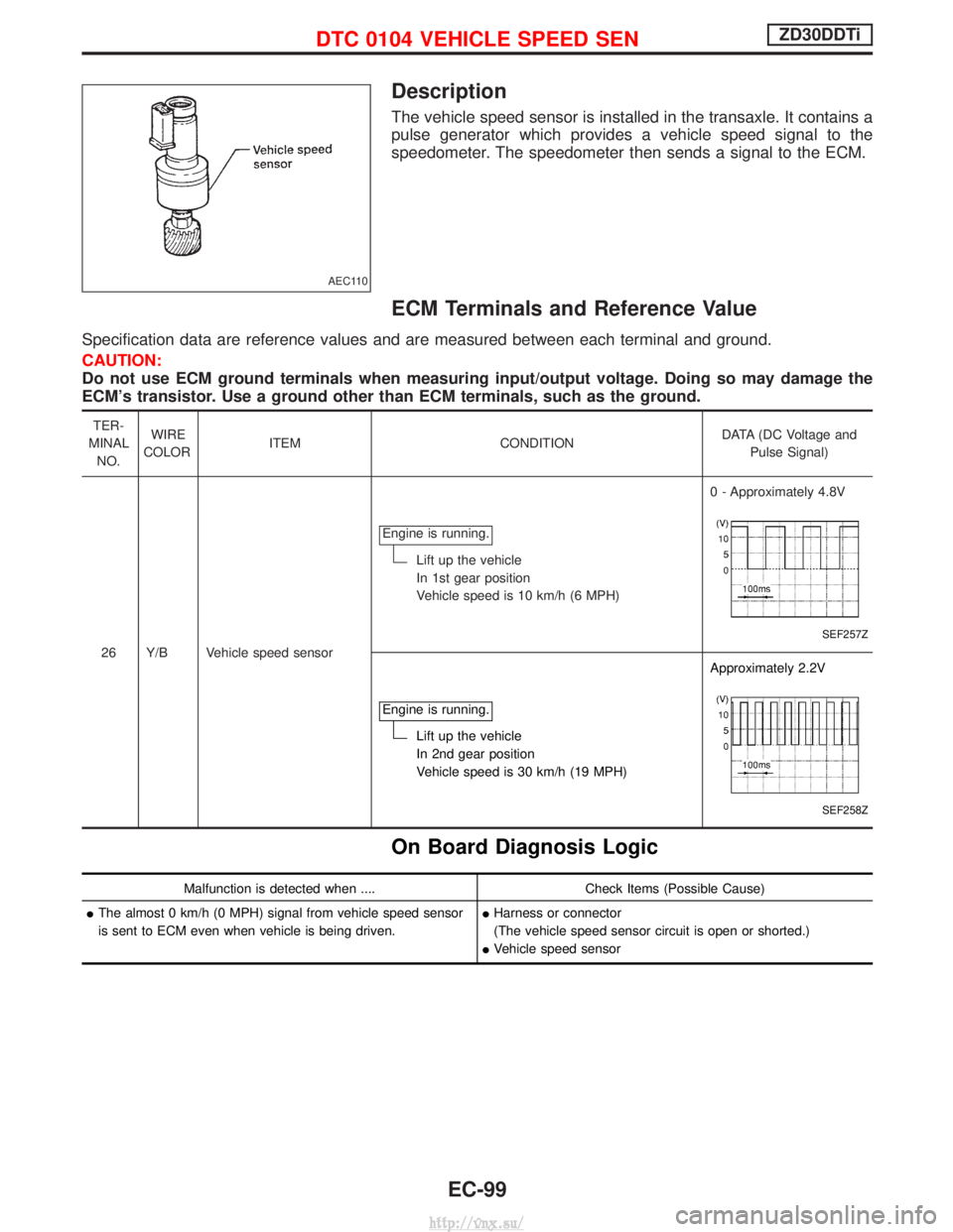
Description
The vehicle speed sensor is installed in the transaxle. It contains a
pulse generator which provides a vehicle speed signal to the
speedometer. The speedometer then sends a signal to the ECM.
ECM Terminals and Reference Value
Specification data are reference values and are measured between each terminal and ground.
CAUTION:
Do not use ECM ground terminals when measuring input/output voltage. Doing so may damage the
ECM's transistor. Use a ground other than ECM terminals, such as the ground.
TER-
MINAL NO. WIRE
COLOR ITEM CONDITION DATA (DC Voltage and
Pulse Signal)
26 Y/B Vehicle speed sensor Engine is running.
Lift up the vehicle
In 1st gear position
Vehicle speed is 10 km/h (6 MPH)
0 - Approximately 4.8V
SEF257Z
Engine is running.
Lift up the vehicle
In 2nd gear position
Vehicle speed is 30 km/h (19 MPH)Approximately 2.2V
SEF258Z
On Board Diagnosis Logic
Malfunction is detected when ....
Check Items (Possible Cause)
I The almost 0 km/h (0 MPH) signal from vehicle speed sensor
is sent to ECM even when vehicle is being driven. I
Harness or connector
(The vehicle speed sensor circuit is open or shorted.)
I Vehicle speed sensor
AEC110
DTC 0104 VEHICLE SPEED SENZD30DDTi
EC-99
http://vnx.su/
Page 375 of 1833
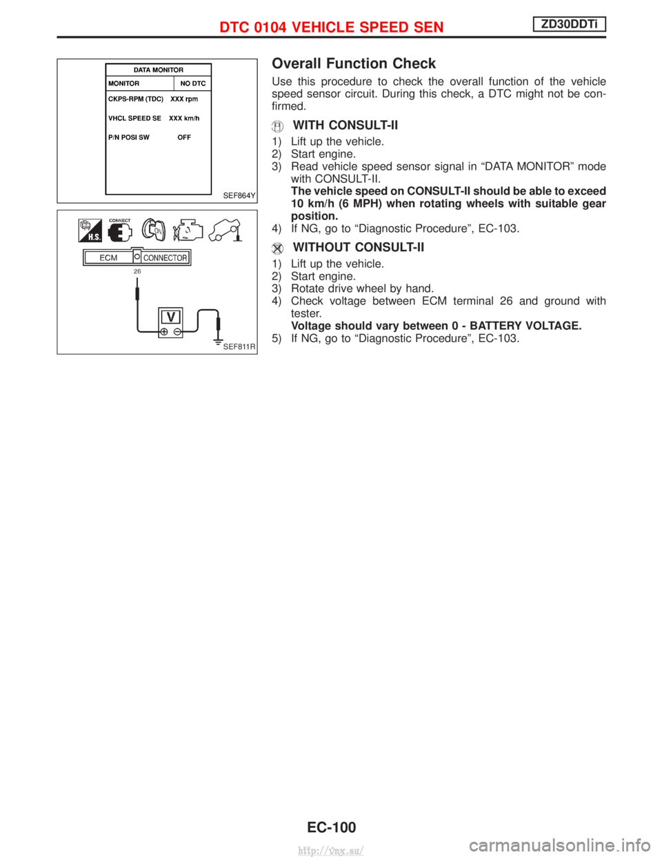
Overall Function Check
Use this procedure to check the overall function of the vehicle
speed sensor circuit. During this check, a DTC might not be con-
firmed.
WITH CONSULT-II
1) Lift up the vehicle.
2) Start engine.
3) Read vehicle speed sensor signal in ªDATA MONITORº modewith CONSULT-II.
The vehicle speed on CONSULT-II should be able to exceed
10 km/h (6 MPH) when rotating wheels with suitable gear
position.
4) If NG, go to ªDiagnostic Procedureº, EC-103.
WITHOUT CONSULT-II
1) Lift up the vehicle.
2) Start engine.
3) Rotate drive wheel by hand.
4) Check voltage between ECM terminal 26 and ground with tester.
Voltage should vary between0-BA TTERY VOLTAGE.
5) If NG, go to ªDiagnostic Procedureº, EC-103.
SEF864Y
SEF811R
DTC 0104 VEHICLE SPEED SENZD30DDTi
EC-100
http://vnx.su/
Page 378 of 1833

Diagnostic Procedure
1 CHECK VEHICLE SPEED SENSOR INPUT SIGNAL CIRCUIT FOR OPEN AND SHORT
1. Turn ignition switch ªOFFº.
2. Disconnect ECM harness connector and combination meter harness connector.
3. Check harness continuity between ECM terminal 26 and combination meter terminal 26. Refer to Wiring Diagram.Continuity should exist.
4. Also check harness for short to ground and short to power.
OK or NG
OK EGO TO 2.
NG ERepair open circuit or short to ground or short to power in harness or connectors.
2 CHECK SPEEDOMETER FUNCTION
Make sure that speedometer functions properly.
OK or NG
OK EGO TO 4.
NG EGO TO 3.
3 CHECK SPEEDOMETER CIRCUIT FOR OPEN AND SHORT
Check the following.
IHarness connectors F108, E225
I Harness connectors M842, F135 (RHD models)
I Harness for open or short between combination meter and vehicle speed sensor
OK or NG
OK ECheck vehicle speed sensor and combination meter. Refer to EL section.
NG ERepair open circuit or short to ground or short to power in harness or connectors.
4 CHECK INTERMITTENT INCIDENT
Refer to ªTROUBLE DIAGNOSIS FOR INTERMITTENT INCIDENTº, EC-78.
EINSPECTION END
DTC 0104 VEHICLE SPEED SENZD30DDTi
EC-103
http://vnx.su/