2004 NISSAN TERRANO electrical
[x] Cancel search: electricalPage 654 of 1833
Component Description
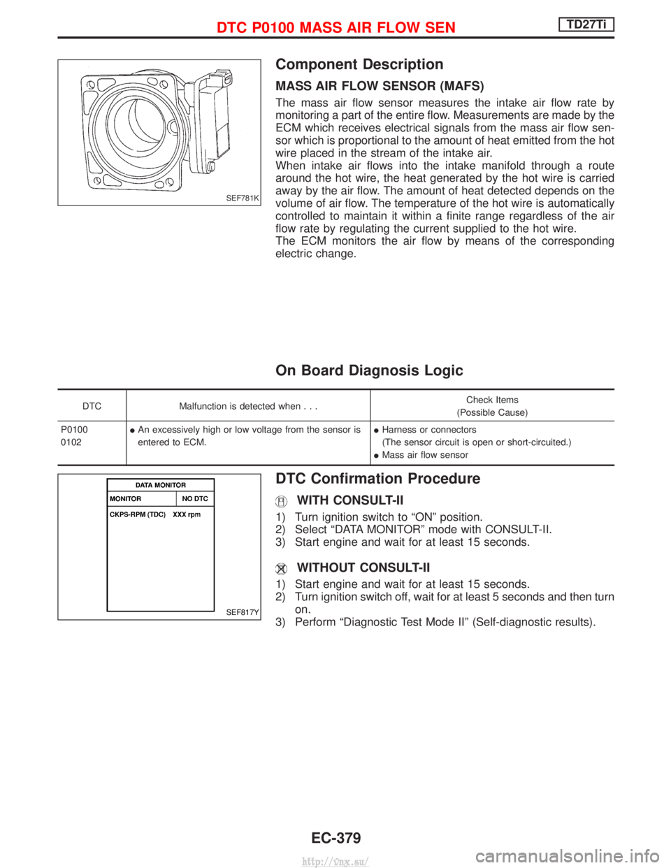
MASS AIR FLOW SENSOR (MAFS)
The mass air flow sensor measures the intake air flow rate by
monitoring a part of the entire flow. Measurements are made by the
ECM which receives electrical signals from the mass air flow sen-
sor which is proportional to the amount of heat emitted from the hot
wire placed in the stream of the intake air.
When intake air flows into the intake manifold through a route
around the hot wire, the heat generated by the hot wire is carried
away by the air flow. The amount of heat detected depends on the
volume of air flow. The temperature of the hot wire is automatically
controlled to maintain it within a finite range regardless of the air
flow rate by regulating the current supplied to the hot wire.
The ECM monitors the air flow by means of the corresponding
electric change.
On Board Diagnosis Logic
DTCMalfunction is detected when... Check Items
(Possible Cause)
P0100
0102 I
An excessively high or low voltage from the sensor is
entered to ECM. I
Harness or connectors
(The sensor circuit is open or short-circuited.)
I Mass air flow sensor
DTC Confirmation Procedure
WITH CONSULT-II
1) Turn ignition switch to ªONº position.
2) Select ªDATA MONITORº mode with CONSULT-II.
3) Start engine and wait for at least 15 seconds.
WITHOUT CONSULT-II
1) Start engine and wait for at least 15 seconds.
2) Turn ignition switch off, wait for at least 5 seconds and then turn
on.
3) Perform ªDiagnostic Test Mode IIº (Self-diagnostic results).
SEF781K
SEF817Y
DTC P0100 MASS AIR FLOW SENTD27Ti
EC-379
http://vnx.su/
Page 659 of 1833
Component Description
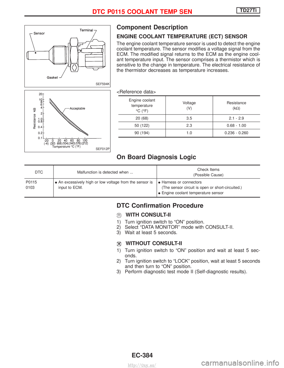
ENGINE COOLANT TEMPERATURE (ECT) SENSOR
The engine coolant temperature sensor is used to detect the engine
coolant temperature. The sensor modifies a voltage signal from the
ECM. The modified signal returns to the ECM as the engine cool-
ant temperature input. The sensor comprises a thermistor which is
sensitive to the change in temperature. The electrical resistance of
the thermistor decreases as temperature increases.
Engine coolanttemperature ÉC (ÉF) Voltage
(V) Resistance
(kW )
20 (68) 3.5 2.1 - 2.9
50 (122) 2.3 0.68 - 1.00
90 (194) 1.0 0.236 - 0.260
On Board Diagnosis Logic
DTC Malfunction is detected when ... Check Items
(Possible Cause)
P0115
0103 I
An excessively high or low voltage from the sensor is
input to ECM. I
Harness or connectors
(The sensor circuit is open or short-circuited.)
I Engine coolant temperature sensor
DTC Confirmation Procedure
WITH CONSULT-II
1) Turn ignition switch to ªONº position.
2) Select ªDATA MONITORº mode with CONSULT-II.
3) Wait at least 5 seconds.
WITHOUT CONSULT-II
1) Turn ignition switch to ªONº position and wait at least 5 sec-
onds.
2) Turn ignition switch to ªLOCKº position, wait at least 5 seconds and then turn to ªONº position.
3) Perform diagnostic test mode II (Self-diagnostic results).
SEF594K
SEF012P
DTC P0115 COOLANT TEMP SENTD27Ti
EC-384
http://vnx.su/
Page 670 of 1833
Component Description
FUEL TEMPERATURE SENSOR (FTS)
The fuel temperature sensor is used to detect the fuel temperature
in the injection pump. The sensor modifies a voltage signal from the
ECM. The modified signal returns to the ECM as the fuel tempera-
ture input. The sensor uses a thermistor which is sensitive to the
change in temperature. The electrical resistance of the thermistor
decreases as temperature increases.
The sensor is built into the inside electrical circuit of the injection
pump.
On Board Diagnosis Logic
DTCMalfunction is detected when ... Check Items
(Possible Cause)
P0180
0402 I
An excessively high or low voltage from the sensor is
detected by ECM. I
Harness or connectors
(The sensor circuit is open or short-circuited.)
I Fuel temperature sensor
DTC Confirmation Procedure
WITH CONSULT-II
1) Turn ignition switch to ªONº position.
2) Select ªDATA MONITORº mode with CONSULT-II.
3) Wait at least 5 seconds.
WITHOUT CONSULT-II
1) Turn ignition switch to ªONº position and wait at least 5 sec-
onds.
2) Turn ignition switch to ªLOCKº position, wait at least 5 seconds and then turn to ªONº position.
3) Perform ªDiagnostic Test Mode IIº (Self-diagnostic results).
DTC P0180 FUEL TEMP SENSORTD27Ti
EC-395
http://vnx.su/
Page 672 of 1833
Diagnostic Procedure
INSPECTION START
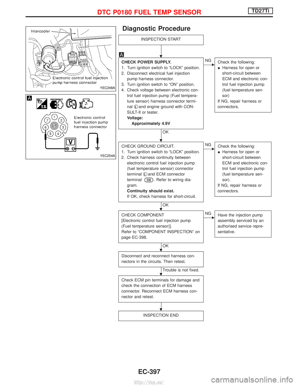
CHECK POWER SUPPLY.
1. Turn ignition switch to ªLOCKº position.
2. Disconnect electrical fuel injection pump harness connector.
3. Turn ignition switch to ªONº position.
4. Check voltage between electronic con- trol fuel injection pump (Fuel tempera-
ture sensor) harness connector termi-
nal q
6and engine ground with CON-
SULT-II or tester.
Voltage: Approximately 4.9V
OK
ENG Check the following:
IHarness for open or
short-circuit between
ECM and electronic con-
trol fuel injection pump
(fuel temperature sen-
sor)
If NG, repair harness or
connectors.
CHECK GROUND CIRCUIT.
1. Turn ignition switch to ªLOCKº position.
2. Check harness continuity between electronic control fuel injection pump
(fuel temperature sensor) connector
terminal q
5and ECM connector
terminal
335. Refer to wiring dia-
gram.
Continuity should exist.
If OK, check harness for short-circuit.
OK
ENG Check the following:
IHarness for open or
short-circuit between
ECM and electronic con-
trol fuel injection pump
(fuel temperature sen-
sor).
If NG, repair harness or
connectors.
CHECK COMPONENT
[Electronic control fuel injection pump
(Fuel temperature sensor)].
Refer to ªCOMPONENT INSPECTIONº on
page EC-398.
OK
ENG Have the injection pump
assembly serviced by an
authorised service repre-
sentative.
Disconnect and reconnect harness con-
nectors in the circuits. Then retest.
Trouble is not fixed.
Check ECM pin terminals for damage and
check the connection of ECM harness
connector. Reconnect ECM harness con-
nector and retest.
INSPECTION END
YEC248A
YEC254A
H
H
H
H
H
H
DTC P0180 FUEL TEMP SENSORTD27Ti
EC-397
http://vnx.su/
Page 714 of 1833

Diagnostic Procedure
INSPECTION START
CHECK POWER SUPPLY CIRCUIT.
1. Turn ignition switch to ªLOCKº position.
2. Disconnect ECM harness connector and electrical fuel injection pump
harness connector.
3. Check harness continuity between electrical fuel injection pump terminal q
2
and ECM connector terminals321.
Refer to wiring diagram.
Continuity should exist.
If OK, check harness for short-circuit.
OK
ENG Check the following:
IHarness for open or
short-circuit between
ECM and control sleeve
position sensor.
If NG, repair harness or
connectors.
CHECK INPUT SIGNAL CIRCUIT.
1. Turn ignition switch to ªLOCKº position.
2. Check harness continuity between con- trol sleeve position sensor connector
terminal q
3and ECM connector termi-
nals
320. Refer to wiring diagram.
Continuity should exist.
If OK, check harness for short-circuit.
OK
ENG Check the following:
IHarness for open or
short-circuit between
ECM and control sleeve
position sensor.
If NG, repair harness or
connectors.
CHECK GROUND CIRCUIT-I.
Check harness continuity between electri-
cal fuel injection pump connector termi-
nals q
1and ECM connector terminals
322. Refer to wiring diagram.
Continuity should exist.
If OK, check harness for short-circuit.
OK
ENG Check the following:
IHarness for open or
short-circuit between
ECM and control sleeve
position sensor.
If NG, repair harness or
connectors.
CHECK GROUND CIRCUIT-II.
Check harness continuity between ECM
connector terminal
327and engine
ground. Refer to wiring diagram.
Continuity should exist.
If OK, check harness for short-circuit.
OK
ENG Check the following:
IHarness for open or
short-circuit.
If NG, repair harness or
connectors.
qA
YEC248A
H
H
H
H
H
DTC P1207 CONT SLEEV POS SENTD27Ti
EC-439
http://vnx.su/
Page 784 of 1833
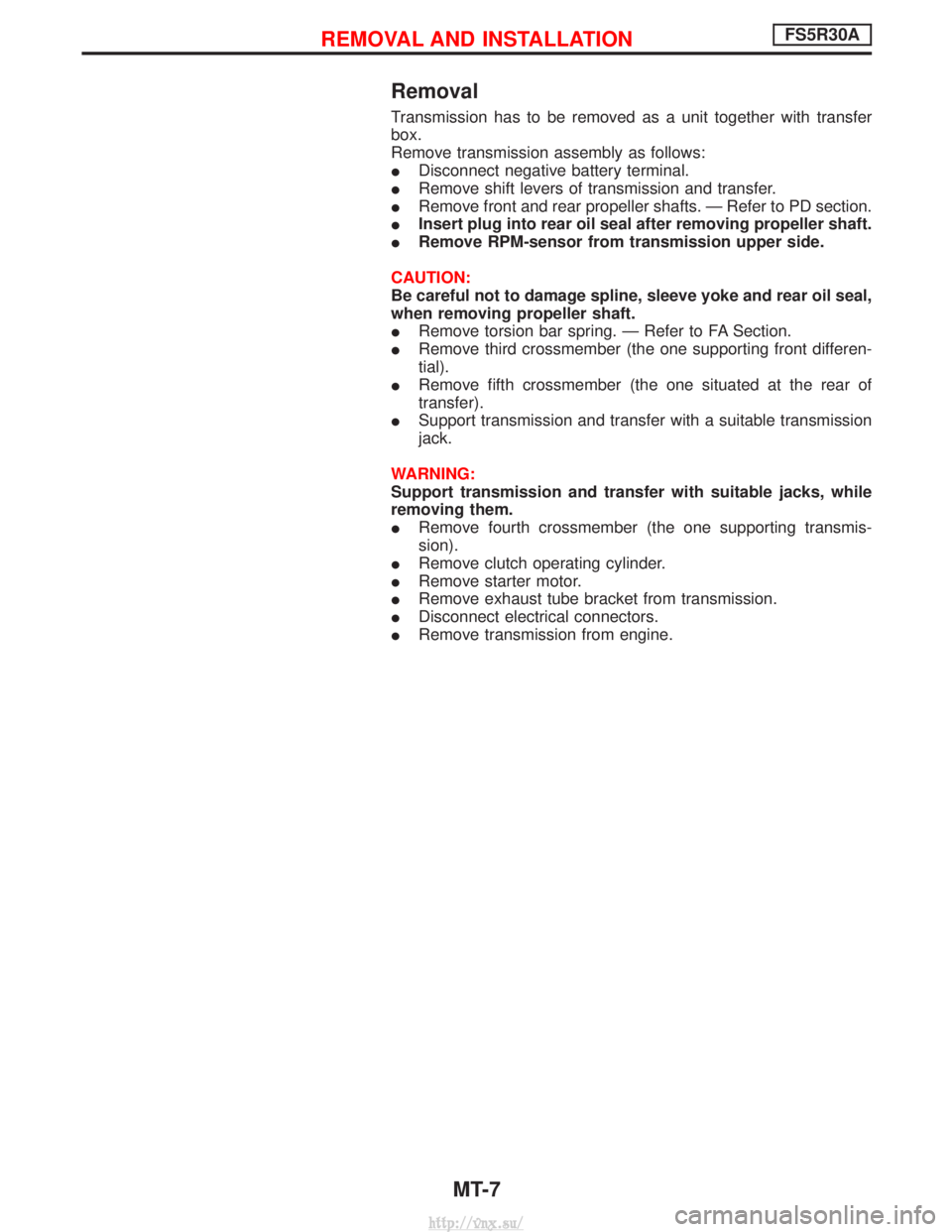
Removal
Transmission has to be removed as a unit together with transfer
box.
Remove transmission assembly as follows:
IDisconnect negative battery terminal.
I Remove shift levers of transmission and transfer.
I Remove front and rear propeller shafts. Ð Refer to PD section.
I Insert plug into rear oil seal after removing propeller shaft.
I Remove RPM-sensor from transmission upper side.
CAUTION:
Be careful not to damage spline, sleeve yoke and rear oil seal,
when removing propeller shaft.
I Remove torsion bar spring. Ð Refer to FA Section.
I Remove third crossmember (the one supporting front differen-
tial).
I Remove fifth crossmember (the one situated at the rear of
transfer).
I Support transmission and transfer with a suitable transmission
jack.
WARNING:
Support transmission and transfer with suitable jacks, while
removing them.
I Remove fourth crossmember (the one supporting transmis-
sion).
I Remove clutch operating cylinder.
I Remove starter motor.
I Remove exhaust tube bracket from transmission.
I Disconnect electrical connectors.
I Remove transmission from engine.
REMOVAL AND INSTALLATIONFS5R30A
MT-7
http://vnx.su/
Page 786 of 1833
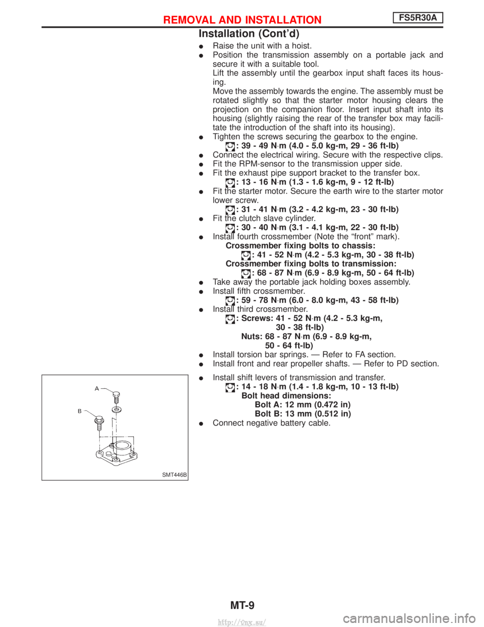
IRaise the unit with a hoist.
I Position the transmission assembly on a portable jack and
secure it with a suitable tool.
Lift the assembly until the gearbox input shaft faces its hous-
ing.
Move the assembly towards the engine. The assembly must be
rotated slightly so that the starter motor housing clears the
projection on the companion floor. Insert input shaft into its
housing (slightly raising the rear of the transfer box may facili-
tate the introduction of the shaft into its housing).
I Tighten the screws securing the gearbox to the engine.
:39-49N ×m (4.0 - 5.0 kg-m, 29 - 36 ft-lb)
I Connect the electrical wiring. Secure with the respective clips.
I Fit the RPM-sensor to the transmission upper side.
I Fit the exhaust pipe support bracket to the transfer box.
:13-16N ×m (1.3 - 1.6 kg-m ,9-12ft-lb)
I Fit the starter motor. Secure the earth wire to the starter motor
lower screw.
:31-41N ×m (3.2 - 4.2 kg-m, 23 - 30 ft-lb)
I Fit the clutch slave cylinder.
:30-40N ×m (3.1 - 4.1 kg-m, 22 - 30 ft-lb)
I Install fourth crossmember (Note the ªfrontº mark).
Crossmember fixing bolts to chassis:
:41-52N ×m (4.2 - 5.3 kg-m, 30 - 38 ft-lb)
Crossmember fixing bolts to transmission:
:68-87N ×m (6.9 - 8.9 kg-m, 50 - 64 ft-lb)
I Take away the portable jack holding boxes assembly.
I Install fifth crossmember.
:59-78N ×m (6.0 - 8.0 kg-m, 43 - 58 ft-lb)
I Install third crossmember.
: Screws: 41 - 52 N ×m (4.2 - 5.3 kg-m,
30 - 38 ft-lb)
Nuts: 68 - 87 N ×m (6.9 - 8.9 kg-m,
50 - 64 ft-lb)
I Install torsion bar springs. Ð Refer to FA section.
I Install front and rear propeller shafts. Ð Refer to PD section.
I Install shift levers of transmission and transfer.
:14-18N ×m (1.4 - 1.8 kg-m, 10 - 13 ft-lb)
Bolt head dimensions: Bolt A: 12 mm (0.472 in)
Bolt B: 13 mm (0.512 in)
I Connect negative battery cable.
SMT446B
REMOVAL AND INSTALLATIONFS5R30A
Installation (Cont'd)
MT-9
http://vnx.su/
Page 814 of 1833
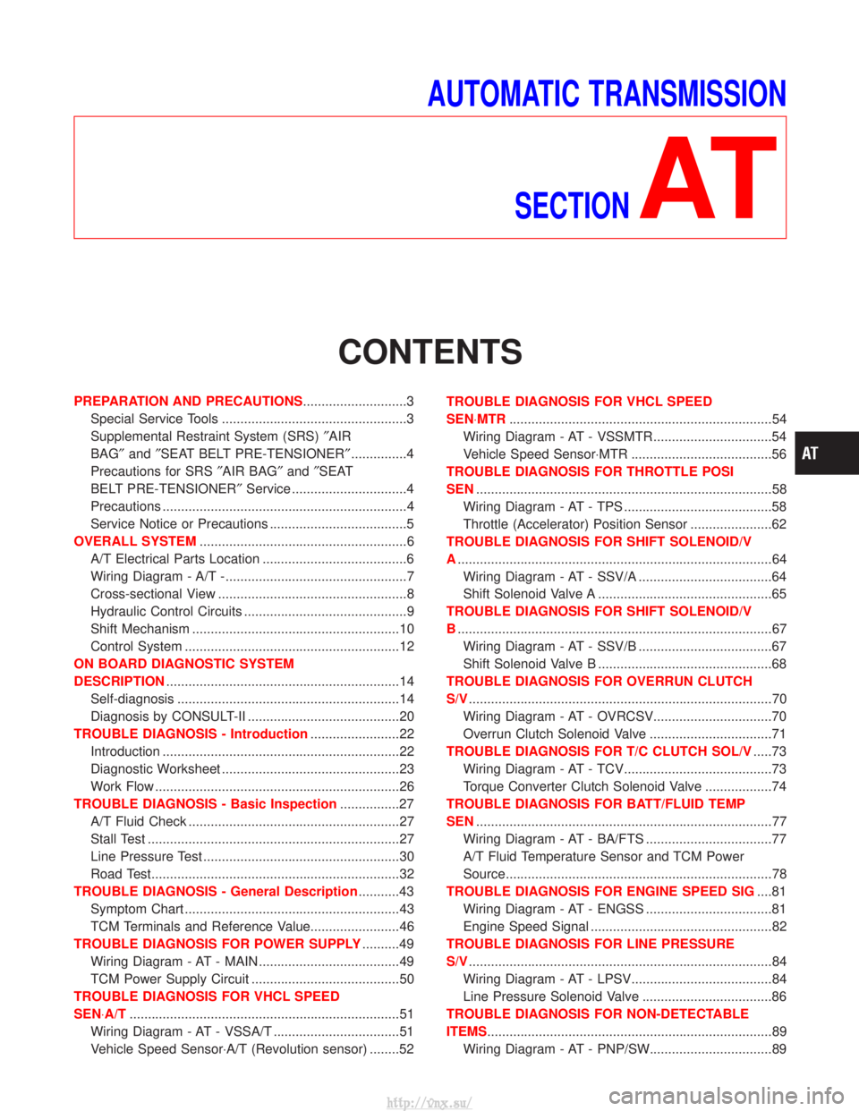
AUTOMATIC TRANSMISSIONSECTION
AT
CONTENTS
PREPARATION AND PRECAUTIONS ............................3
Special Service Tools ..................................................3
Supplemental Restraint System (SRS) ²AIR
BAG² and²SEAT BELT PRE-TENSIONER² ...............4
Precautions for SRS ²AIR BAG² and²SEAT
BELT PRE-TENSIONER² Service ...............................4
Precautions ..................................................................4
Service Notice or Precautions .....................................5
OVERALL SYSTEM ........................................................6
A/T Electrical Parts Location .......................................6
Wiring Diagram - A/T -.................................................7
Cross-sectional View ...................................................8
Hydraulic Control Circuits ............................................9
Shift Mechanism ........................................................10
Control System ..........................................................12
ON BOARD DIAGNOSTIC SYSTEM
DESCRIPTION ...............................................................14
Self-diagnosis ............................................................14
Diagnosis by CONSULT-II .........................................20
TROUBLE DIAGNOSIS - Introduction ........................22
Introduction ................................................................22
Diagnostic Worksheet ................................................23
Work Flow ..................................................................26
TROUBLE DIAGNOSIS - Basic Inspection ................27
A/T Fluid Check .........................................................27
Stall Test ....................................................................27
Line Pressure Test .....................................................30
Road Test...................................................................32
TROUBLE DIAGNOSIS - General Description ...........43
Symptom Chart ..........................................................43
TCM Terminals and Reference Value........................46
TROUBLE DIAGNOSIS FOR POWER SUPPLY ..........49
Wiring Diagram - AT - MAIN ......................................49
TCM Power Supply Circuit ........................................50
TROUBLE DIAGNOSIS FOR VHCL SPEED
SEN×A/T ........................................................................\
.51
Wiring Diagram - AT - VSSA/T ..................................51
Vehicle Speed Sensor×A/T (Revolution sensor) ........52 TROUBLE DIAGNOSIS FOR VHCL SPEED
SEN×MTR
.......................................................................54
Wiring Diagram - AT - VSSMTR ................................54
Vehicle Speed Sensor×MTR ......................................56
TROUBLE DIAGNOSIS FOR THROTTLE POSI
SEN ........................................................................\
........58
Wiring Diagram - AT - TPS ........................................58
Throttle (Accelerator) Position Sensor ......................62
TROUBLE DIAGNOSIS FOR SHIFT SOLENOID/V
A ........................................................................\
.............64
Wiring Diagram - AT - SSV/A ....................................64
Shift Solenoid Valve A ...............................................65
TROUBLE DIAGNOSIS FOR SHIFT SOLENOID/V
B ........................................................................\
.............67
Wiring Diagram - AT - SSV/B ....................................67
Shift Solenoid Valve B ...............................................68
TROUBLE DIAGNOSIS FOR OVERRUN CLUTCH
S/V ........................................................................\
..........70
Wiring Diagram - AT - OVRCSV................................70
Overrun Clutch Solenoid Valve .................................71
TROUBLE DIAGNOSIS FOR T/C CLUTCH SOL/V .....73
Wiring Diagram - AT - TCV........................................73
Torque Converter Clutch Solenoid Valve ..................74
TROUBLE DIAGNOSIS FOR BATT/FLUID TEMP
SEN ........................................................................\
........77
Wiring Diagram - AT - BA/FTS ..................................77
A/T Fluid Temperature Sensor and TCM Power
Source........................................................................\
78
TROUBLE DIAGNOSIS FOR ENGINE SPEED SIG ....81
Wiring Diagram - AT - ENGSS ..................................81
Engine Speed Signal .................................................82
TROUBLE DIAGNOSIS FOR LINE PRESSURE
S/V ........................................................................\
..........84
Wiring Diagram - AT - LPSV......................................84
Line Pressure Solenoid Valve ...................................86
TROUBLE DIAGNOSIS FOR NON-DETECTABLE
ITEMS........................................................................\
.....89 Wiring Diagram - AT - PNP/SW.................................89
http://vnx.su/