2004 NISSAN TERRANO electrical
[x] Cancel search: electricalPage 1303 of 1833
Trouble Diagnoses Introduction
CAUTION:
IDo not use electrical test equipment on any circuit related to the SRS unless instructed to in this
Service Manual. Spiral cable and wiring harnesses covered with yellow insulation tape either just
before the harness connectors or for the complete harness are related to the SRS.
I Do not attempt to repair, splice or modify the SRS wiring harness. If the harness is damaged,
replace it with a new one.
I Keep ground portion clean.
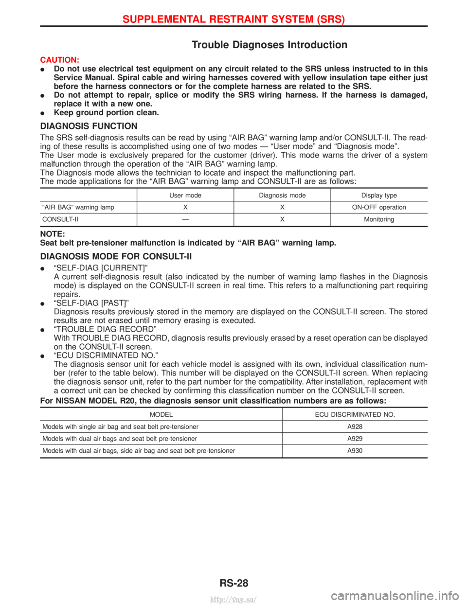
DIAGNOSIS FUNCTION
The SRS self-diagnosis results can be read by using ªAIR BAGº warning lamp and/or CONSULT-II. The read-
ing of these results is accomplished using one of two modes Ð ªUser modeº and ªDiagnosis modeº.
The User mode is exclusively prepared for the customer (driver). This mode warns the driver of a system
malfunction through the operation of the ªAIR BAGº warning lamp.
The Diagnosis mode allows the technician to locate and inspect the malfunctioning part.
The mode applications for the ªAIR BAGº warning lamp and CONSULT-II are as follows:
User mode Diagnosis mode Display type
ªAIR BAGº warning lamp X X ON-OFF operation
CONSULT-II Ð X Monitoring
NOTE:
Seat belt pre-tensioner malfunction is indicated by ªAIR BAGº warning lamp.
DIAGNOSIS MODE FOR CONSULT-II
I ªSELF-DIAG [CURRENT]º
A current self-diagnosis result (also indicated by the number of warning lamp flashes in the Diagnosis
mode) is displayed on the CONSULT-II screen in real time. This refers to a malfunctioning part requiring
repairs.
I ªSELF-DIAG [PAST]º
Diagnosis results previously stored in the memory are displayed on the CONSULT-II screen. The stored
results are not erased until memory erasing is executed.
I ªTROUBLE DIAG RECORDº
With TROUBLE DIAG RECORD, diagnosis results previously erased by a reset operation can be displayed
on the CONSULT-II screen.
I ªECU DISCRIMINATED NO.º
The diagnosis sensor unit for each vehicle model is assigned with its own, individual classification num-
ber (refer to the table below). This number will be displayed on the CONSULT-II screen. When replacing
the diagnosis sensor unit, refer to the part number for the compatibility. After installation, replacement with
a correct unit can be checked by confirming this classification number on the CONSULT-II screen.
For NISSAN MODEL R20, the diagnosis sensor unit classification numbers are as follows:
MODEL ECU DISCRIMINATED NO.
Models with single air bag and seat belt pre-tensioner A928
Models with dual air bags and seat belt pre-tensioner A929
Models with dual air bags, side air bag and seat belt pre-tensioner A930
SUPPLEMENTAL RESTRAINT SYSTEM (SRS)
RS-28
http://vnx.su/
Page 1339 of 1833
Service Notice
IWhen removing or installing various parts, place a cloth or padding onto the vehicle body to prevent
scratches.
I Handle trim, molding, instruments, grille, etc. carefully during removing or installing. Be careful not to oil
or damage them.
I Apply sealing compound where necessary when installing parts.
I When applying sealing compound, be careful that the sealing compound does not protrude from parts.
I When replacing any metal parts (for example body outer panel, members, etc.), be sure to take rust pre-
vention measures.
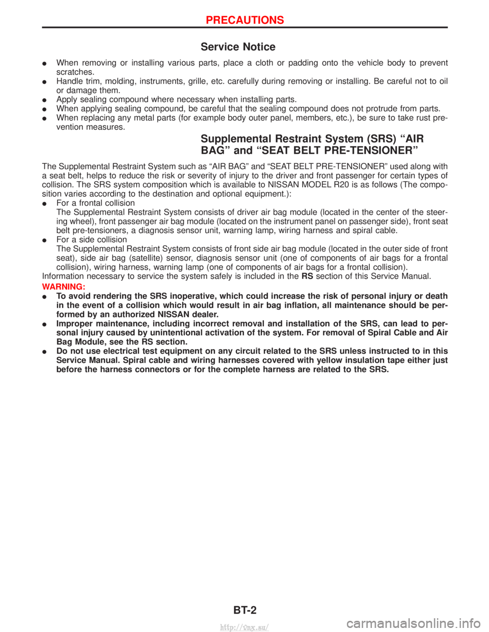
Supplemental Restraint System (SRS) ªAIR
BAGº and ªSEAT BELT PRE-TENSIONERº
The Supplemental Restraint System such as ªAIR BAGº and ªSEAT BELT PRE-TENSIONERº used along with
a seat belt, helps to reduce the risk or severity of injury to the driver and front passenger for certain types of
collision. The SRS system composition which is available to NISSAN MODEL R20 is as follows (The compo-
sition varies according to the destination and optional equipment.):
IFor a frontal collision
The Supplemental Restraint System consists of driver air bag module (located in the center of the steer-
ing wheel), front passenger air bag module (located on the instrument panel on passenger side), front seat
belt pre-tensioners, a diagnosis sensor unit, warning lamp, wiring harness and spiral cable.
I For a side collision
The Supplemental Restraint System consists of front side air bag module (located in the outer side of front
seat), side air bag (satellite) sensor, diagnosis sensor unit (one of components of air bags for a frontal
collision), wiring harness, warning lamp (one of components of air bags for a frontal collision).
Information necessary to service the system safely is included in the RSsection of this Service Manual.
WARNING:
I To avoid rendering the SRS inoperative, which could increase the risk of personal injury or death
in the event of a collision which would result in air bag inflation, all maintenance should be per-
formed by an authorized NISSAN dealer.
I Improper maintenance, including incorrect removal and installation of the SRS, can lead to per-
sonal injury caused by unintentional activation of the system. For removal of Spiral Cable and Air
Bag Module, see the RS section.
I Do not use electrical test equipment on any circuit related to the SRS unless instructed to in this
Service Manual. Spiral cable and wiring harnesses covered with yellow insulation tape either just
before the harness connectors or for the complete harness are related to the SRS.
PRECAUTIONS
BT-2
http://vnx.su/
Page 1398 of 1833
HEATER & AIR CONDITIONERSECTION
HA
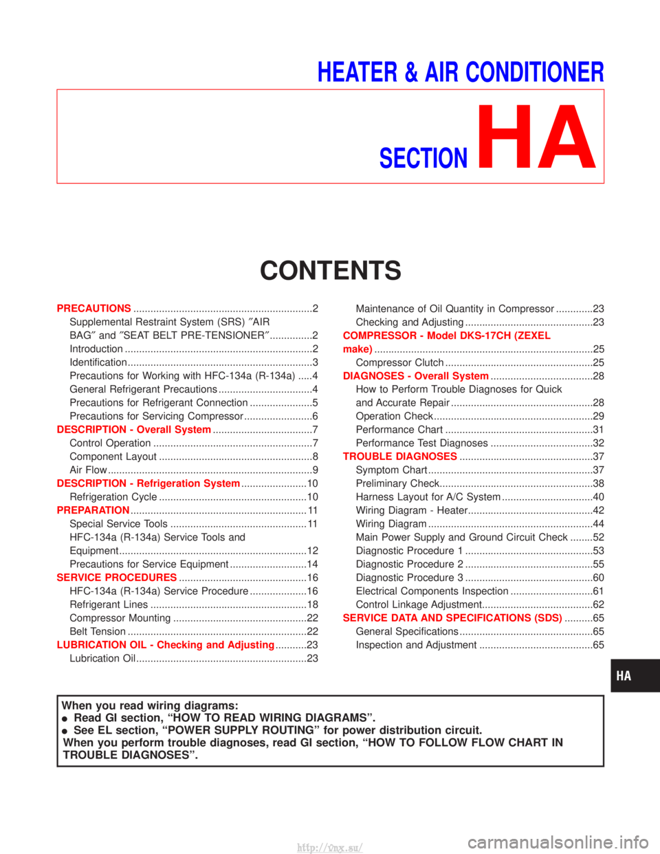
CONTENTS
PRECAUTIONS ...............................................................2
Supplemental Restraint System (SRS) ²AIR
BAG² and²SEAT BELT PRE-TENSIONER² ...............2
Introduction ..................................................................2
Identification .................................................................3
Precautions for Working with HFC-134a (R-134a) .....4
General Refrigerant Precautions .................................4
Precautions for Refrigerant Connection ......................5
Precautions for Servicing Compressor ........................6
DESCRIPTION - Overall System ...................................7
Control Operation ........................................................7
Component Layout ......................................................8
Air Flow ........................................................................\
9
DESCRIPTION - Refrigeration System .......................10
Refrigeration Cycle ....................................................10
PREPARATION .............................................................. 11
Special Service Tools ................................................ 11
HFC-134a (R-134a) Service Tools and
Equipment ..................................................................12
Precautions for Service Equipment ...........................14
SERVICE PROCEDURES .............................................16
HFC-134a (R-134a) Service Procedure ....................16
Refrigerant Lines .......................................................18
Compressor Mounting ...............................................22
Belt Tension ...............................................................22
LUBRICATION OIL - Checking and Adjusting ...........23
Lubrication Oil ............................................................23 Maintenance of Oil Quantity in Compressor .............23
Checking and Adjusting .............................................23
COMPRESSOR - Model DKS-17CH (ZEXEL
make) ........................................................................\
.....25
Compressor Clutch ....................................................25
DIAGNOSES - Overall System ....................................28
How to Perform Trouble Diagnoses for Quick
and Accurate Repair ..................................................28
Operation Check ........................................................29
Performance Chart ....................................................31
Performance Test Diagnoses ....................................32
TROUBLE DIAGNOSES ...............................................37
Symptom Chart ..........................................................37
Preliminary Check......................................................38
Harness Layout for A/C System ................................40
Wiring Diagram - Heater............................................42
Wiring Diagram ..........................................................44
Main Power Supply and Ground Circuit Check ........52
Diagnostic Procedure 1 .............................................53
Diagnostic Procedure 2 .............................................55
Diagnostic Procedure 3 .............................................60
Electrical Components Inspection .............................61
Control Linkage Adjustment.......................................62
SERVICE DATA AND SPECIFICATIONS (SDS) ..........65
General Specifications ...............................................65
Inspection and Adjustment ........................................65
When you read wiring diagrams:
I Read GI section, ªHOW TO READ WIRING DIAGRAMSº.
I See EL section, ªPOWER SUPPLY ROUTINGº for power distribution circuit.
When you perform trouble diagnoses, read GI section, ªHOW TO FOLLOW FLOW CHART IN
TROUBLE DIAGNOSESº.
http://vnx.su/
Page 1399 of 1833
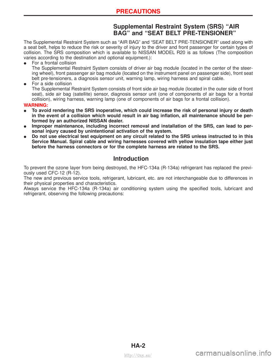
Supplemental Restraint System (SRS) ªAIR
BAGº and ªSEAT BELT PRE-TENSIONERº
The Supplemental Restraint System such as ªAIR BAGº and ªSEAT BELT PRE-TENSIONERº used along with
a seat belt, helps to reduce the risk or severity of injury to the driver and front passenger for certain types of
collision. The SRS composition which is available to NISSAN MODEL R20 is as follows (The composition
varies according to the destination and optional equipment.):
IFor a frontal collision
The Supplemental Restraint System consists of driver air bag module (located in the center of the steer-
ing wheel), front passenger air bag module (located on the instrument panel on passenger side), front seat
belt pre-tensioners, a diagnosis sensor unit, warning lamp, wiring harness and spiral cable.
I For a side collision
The Supplemental Restraint System consists of front side air bag module (located in the outer side of front
seat), side air bag (satellite) sensor, diagnosis sensor unit (one of components of air bags for a frontal
collision), wiring harness, warning lamp (one of components of air bags for a frontal collision).
WARNING:
I To avoid rendering the SRS inoperative, which could increase the risk of personal injury or death
in the event of a collision which would result in air bag inflation, all maintenance should be per-
formed by an authorized NISSAN dealer.
I Improper maintenance, including incorrect removal and installation of the SRS, can lead to per-
sonal injury caused by unintentional activation of the system.
I Do not use electrical test equipment on any circuit related to the SRS unless instructed to in this
Service Manual. Spiral cable and wiring harnesses covered with yellow insulation tape either just
before the harness connectors or for the complete harness are related to the SRS.
Introduction
To prevent the ozone layer from being destroyed, the HFC-134a (R-134a) refrigerant has replaced the previ-
ously used CFC-12 (R-12).
The new and previous service tools, refrigerant, lubricant, etc. are not interchangeable due to differences in
their physical properties and characteristics.
Always service the HFC-134a (R-134a) air conditioning system using the specified tools, lubricant and
refrigerant, observing the following precautions:
PRECAUTIONS
HA-2
http://vnx.su/
Page 1409 of 1833
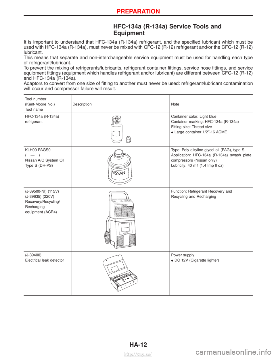
HFC-134a (R-134a) Service Tools and
Equipment
It is important to understand that HFC-134a (R-134a) refrigerant, and the specified lubricant which must be
used with HFC-134a (R-134a), must never be mixed with CFC-12 (R-12) refrigerant and/or the CFC-12 (R-12)
lubricant.
This means that separate and non-interchangeable service equipment must be used for handling each type
of refrigerant/lubricant.
To prevent the mixing of refrigerants/lubricants, refrigerant container fittings, service hose fittings, and service
equipment fittings (equipment which handles refrigerant and/or lubricant) are different between CFC-12 (R-12)
and HFC-134a (R-134a).
Adaptors to convert from one size of fitting to another must never be used: refrigerant/lubricant contamination
will occur and compressor failure will result.
Tool number
(Kent-Moore No.)
Tool nameDescription Note
HFC-134a (R-134a)
refrigerant
Container color: Light blue
Container marking: HFC-134a (R-134a)
Fitting size: Thread size
I Large container 1/2² -16 ACME
KLH00-PAGS0
(Ð)
Nissan A/C System Oil
Type S (DH-PS)
Type: Poly alkyline glycol oil (PAG), type S
Application: HFC-134a (R-134a) swash plate
compressors (Nissan only)
Lubricity: 40 m (1.4 Imp fl oz)
(J-39500-NI) (115V)
(J-39635) (220V)
Recovery/Recycling/
Recharging
equipment (ACR4)
Function: Refrigerant Recovery and
Recycling and Recharging
(J-39400)
Electrical leak detector
Power supply:
I DC 12V (Cigarette lighter)
PREPARATION
HA-12
http://vnx.su/
Page 1425 of 1833
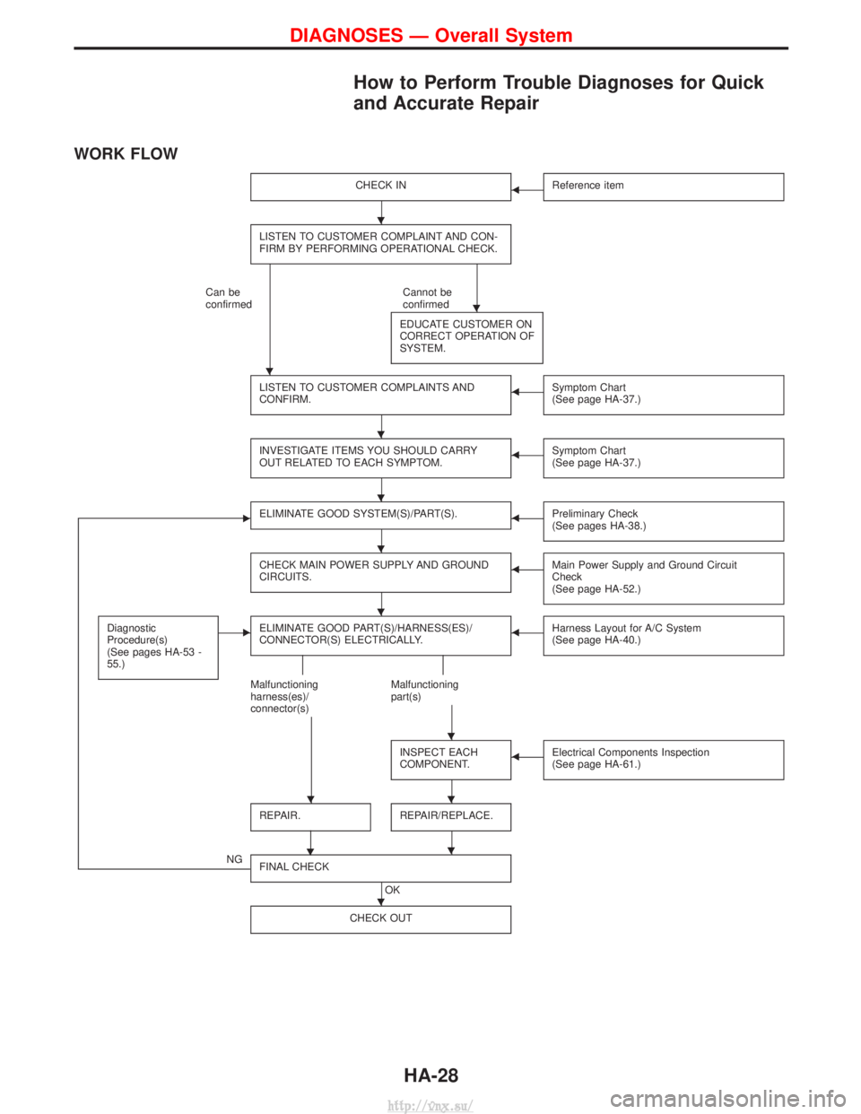
How to Perform Trouble Diagnoses for Quick
and Accurate Repair
WORK FLOW
CHECK INFReference item
LISTEN TO CUSTOMER COMPLAINT AND CON-
FIRM BY PERFORMING OPERATIONAL CHECK.
Can be
confirmedCannot be
confirmed
EDUCATE CUSTOMER ON
CORRECT OPERATION OF
SYSTEM.
LISTEN TO CUSTOMER COMPLAINTS AND
CONFIRM.FSymptom Chart
(See page HA-37.)
INVESTIGATE ITEMS YOU SHOULD CARRY
OUT RELATED TO EACH SYMPTOM.FSymptom Chart
(See page HA-37.)
EELIMINATE GOOD SYSTEM(S)/PART(S).FPreliminary Check
(See pages HA-38.)
CHECK MAIN POWER SUPPLY AND GROUND
CIRCUITS.FMain Power Supply and Ground Circuit
Check
(See page HA-52.)
Diagnostic
Procedure(s)
(See pages HA-53 -
55.)EELIMINATE GOOD PART(S)/HARNESS(ES)/
CONNECTOR(S) ELECTRICALLY.FHarness Layout for A/C System
(See page HA-40.)
Malfunctioning
harness(es)/
connector(s) Malfunctioning
part(s)
INSPECT EACH
COMPONENT.
FElectrical Components Inspection
(See page HA-61.)
REPAIR.
H
REPAIR/REPLACE.
NG FINAL CHECK
OK
CHECK OUT
H
H
H
H
H
H
H
H
HH
H
H
DIAGNOSES Ð Overall System
HA-28
http://vnx.su/
Page 1434 of 1833
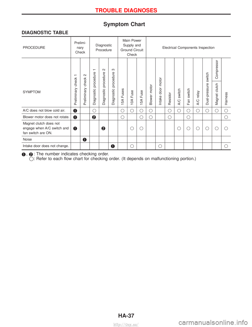
Symptom Chart
DIAGNOSTIC TABLE
PROCEDUREPrelimi-
nary
Check Diagnostic
Procedure Main Power
Supply and
Ground Circuit Check Electrical Components Inspection
SYMPTOM
Preliminary check 1
Preliminary check 2
Diagnostic procedure 1
Diagnostic procedure 2
Diagnostic procedure 3
15A Fuses
10A Fuse
15A Fuse
Blower motor
Intake door motor
Resistor
A/C switch
Fan switch
A/C relay
Dual-pressure switch Compressor
Harness Magnet clutch
A/C does not blow cold air.q qqqq qqqqqqq
Blower motor does not rotate.
qqqqq q
Magnet clutch does not
engage when A/C switch and
fan switch are ON.
qq qqqqqq
Noise
Intake door does not change.qq q
,: The number indicates checking order.
q: Refer to each flow chart for checking order. (It depends on malfunctioning portion.)
TROUBLE DIAGNOSES
HA-37
http://vnx.su/
Page 1435 of 1833
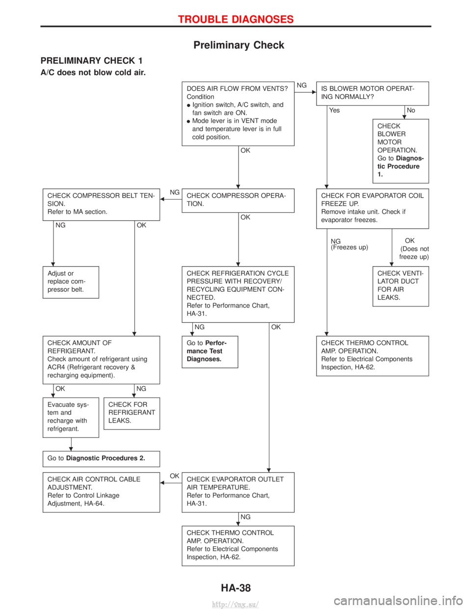
Preliminary Check
PRELIMINARY CHECK 1
A/C does not blow cold air.
DOES AIR FLOW FROM VENTS?
Condition
IIgnition switch, A/C switch, and
fan switch are ON.
I Mode lever is in VENT mode
and temperature lever is in full
cold position.
OK
ENG
IS BLOWER MOTOR OPERAT-
ING NORMALLY?
Ye s N o
CHECK
BLOWER
MOTOR
OPERATION.
Go to Diagnos-
tic Procedure
1.
CHECK COMPRESSOR BELT TEN-
SION.
Refer to MA section.
NG OK
FNG
CHECK COMPRESSOR OPERA-
TION.
OK CHECK FOR EVAPORATOR COIL
FREEZE UP.
Remove intake unit. Check if
evaporator freezes.
NG
(Freezes up)
OK
(Does not
freeze up)
Adjust or
replace com-
pressor belt.
CHECK REFRIGERATION CYCLE
PRESSURE WITH RECOVERY/
RECYCLING EQUIPMENT CON-
NECTED.
Refer to Performance Chart,
HA-31.
NG OK CHECK VENTI-
LATOR DUCT
FOR AIR
LEAKS.
CHECK AMOUNT OF
REFRIGERANT.
Check amount of refrigerant using
ACR4 (Refrigerant recovery &
recharging equipment).
OK
NGGo to
Perfor-
mance Test
Diagnoses.
CHECK THERMO CONTROL
AMP. OPERATION.
Refer to Electrical Components
Inspection, HA-62.
Evacuate sys-
tem and
recharge with
refrigerant.CHECK FOR
REFRIGERANT
LEAKS.
Go to Diagnostic Procedures 2.
CHECK AIR CONTROL CABLE
ADJUSTMENT.
Refer to Control Linkage
Adjustment, HA-64.FOK
CHECK EVAPORATOR OUTLET
AIR TEMPERATURE.
Refer to Performance Chart,
HA-31.
NG
CHECK THERMO CONTROL
AMP. OPERATION.
Refer to Electrical Components
Inspection, HA-62.
H
HH
HHH
HHH
HH
H
H
H
TROUBLE DIAGNOSES
HA-38
http://vnx.su/