Page 324 of 1833

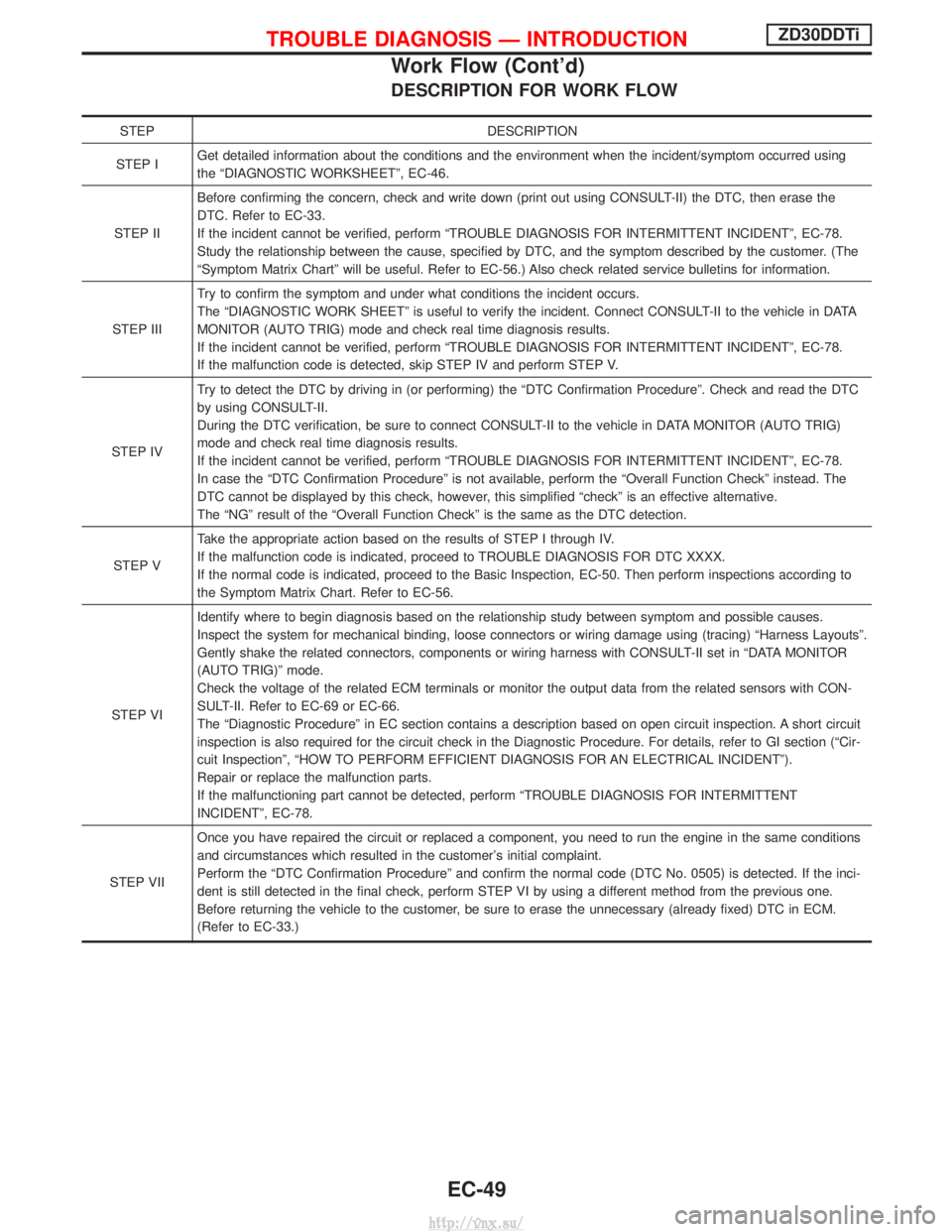
DESCRIPTION FOR WORK FLOW
STEPDESCRIPTION
STEP I Get detailed information about the conditions and the environment when the incident/symptom occurred using
the ªDIAGNOSTIC WORKSHEETº, EC-46.
STEP II Before confirming the concern, check and write down (print out using CONSULT-II) the DTC, then erase the
DTC. Refer to EC-33.
If the incident cannot be verified, perform ªTROUBLE DIAGNOSIS FOR INTERMITTENT INCIDENTº, EC-78.
Study the relationship between the cause, specified by DTC, and the symptom described by the customer. (The
ªSymptom Matrix Chartº will be useful. Refer to EC-56.) Also check related service bulletins for information.
STEP III Try to confirm the symptom and under what conditions the incident occurs.
The ªDIAGNOSTIC WORK SHEETº is useful to verify the incident. Connect CONSULT-II to the vehicle in DATA
MONITOR (AUTO TRIG) mode and check real time diagnosis results.
If the incident cannot be verified, perform ªTROUBLE DIAGNOSIS FOR INTERMITTENT INCIDENTº, EC-78.
If the malfunction code is detected, skip STEP IV and perform STEP V.
STEP IV Try to detect the DTC by driving in (or performing) the ªDTC Confirmation Procedureº. Check and read the DTC
by using CONSULT-II.
During the DTC verification, be sure to connect CONSULT-II to the vehicle in DATA MONITOR (AUTO TRIG)
mode and check real time diagnosis results.
If the incident cannot be verified, perform ªTROUBLE DIAGNOSIS FOR INTERMITTENT INCIDENTº, EC-78.
In case the ªDTC Confirmation Procedureº is not available, perform the ªOverall Function Checkº instead. The
DTC cannot be displayed by this check, however, this simplified ªcheckº is an effective alternative.
The ªNGº result of the ªOverall Function Checkº is the same as the DTC detection.
STEP V Take the appropriate action based on the results of STEP I through IV.
If the malfunction code is indicated, proceed to TROUBLE DIAGNOSIS FOR DTC XXXX.
If the normal code is indicated, proceed to the Basic Inspection, EC-50. Then perform inspections according to
the Symptom Matrix Chart. Refer to EC-56.
STEP VI Identify where to begin diagnosis based on the relationship study between symptom and possible causes.
Inspect the system for mechanical binding, loose connectors or wiring damage using (tracing) ªHarness Layoutsº.
Gently shake the related connectors, components or wiring harness with CONSULT-II set in ªDATA MONITOR
(AUTO TRIG)º mode.
Check the voltage of the related ECM terminals or monitor the output data from the related sensors with CON-
SULT-II. Refer to EC-69 or EC-66.
The ªDiagnostic Procedureº in EC section contains a description based on open circuit inspection. A short circuit
inspection is also required for the circuit check in the Diagnostic Procedure. For details, refer to GI section (ªCir-
cuit Inspectionº, ªHOW TO PERFORM EFFICIENT DIAGNOSIS FOR AN ELECTRICAL INCIDENTº).
Repair or replace the malfunction parts.
If the malfunctioning part cannot be detected, perform ªTROUBLE DIAGNOSIS FOR INTERMITTENT
INCIDENTº, EC-78.
STEP VII Once you have repaired the circuit or replaced a component, you need to run the engine in the same conditions
and circumstances which resulted in the customer's initial complaint.
Perform the ªDTC Confirmation Procedureº and confirm the normal code (DTC No. 0505) is detected. If the inci-
dent is still detected in the final check, perform STEP VI by using a different method from the previous one.
Before returning the vehicle to the customer, be sure to erase the unnecessary (already fixed) DTC in ECM.
(Refer to EC-33.)
TROUBLE DIAGNOSIS Ð INTRODUCTIONZD30DDTi
Work Flow (Cont'd)
EC-49
http://vnx.su/
Page 397 of 1833
Diagnostic Procedure
1 INSPECTION START
With CONSULT-II
1. Turn ignition switch ªONº.
2. Select ªSELF DIAG RESULTSº mode with CONSULT-II.
3. Touch ªERASEº.
4. Perform ªDTC Confirmation Procedureº, EC-121, again.
5. Is the malfunction displayed again?
Without CONSULT-II
1. Turn ignition switch ªONº.
2. Erase the Diagnostic Test Mode II (Self-diagnostic results) memory.
3. Perform ªDTC Confirmation Procedureº, EC-121, again.
4. Perform ªDiagnostic Test Mode II (Self-diagnostic results)º.
5. Is the DTC 0301 displayed again?
YesorNo
Ye s EReplace ECM.
No EINSPECTION END
DTC 0301 ECM 2ZD30DDTi
EC-122
http://vnx.su/
Page 425 of 1833

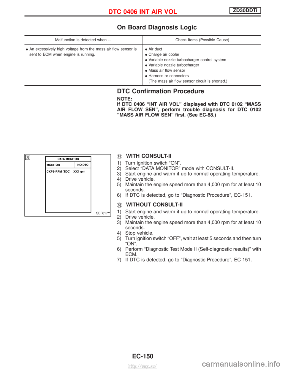
On Board Diagnosis Logic
Malfunction is detected when ...Check Items (Possible Cause)
I An excessively high voltage from the mass air flow sensor is
sent to ECM when engine is running. I
Air duct
I Charge air cooler
I Variable nozzle turbocharger control system
I Variable nozzle turbocharger
I Mass air flow sensor
I Harness or connectors
(The mass air flow sensor circuit is shorted.)
DTC Confirmation Procedure
NOTE:
If DTC 0406 ªINT AIR VOLº displayed with DTC 0102 ªMASS
AIR FLOW SENº, perform trouble diagnosis for DTC 0102
ªMASS AIR FLOW SENº first. (See EC-88.)
WITH CONSULT-II
1) Turn ignition switch ªONº.
2) Select ªDATA MONITORº mode with CONSULT-II.
3) Start engine and warm it up to normal operating temperature.
4) Drive vehicle.
5) Maintain the engine speed more than 4,000 rpm for at least 10
seconds.
6) If DTC is detected, go to ªDiagnostic Procedureº, EC-151.
WITHOUT CONSULT-II
1) Start engine and warm it up to normal operating temperature.
2) Drive vehicle.
3) Maintain the engine speed more than 4,000 rpm for at least 10 seconds.
4) Stop vehicle.
5) Turn ignition switch ªOFFº, wait at least 5 seconds and then turn ªONº.
6) Perform ªDiagnostic Test Mode II (Self-diagnostic results)º with ECM.
7) If DTC is detected, go to ªDiagnostic Procedureº, EC-151.SEF817Y
DTC 0406 INT AIR VOLZD30DDTi
EC-150
http://vnx.su/
Page 471 of 1833

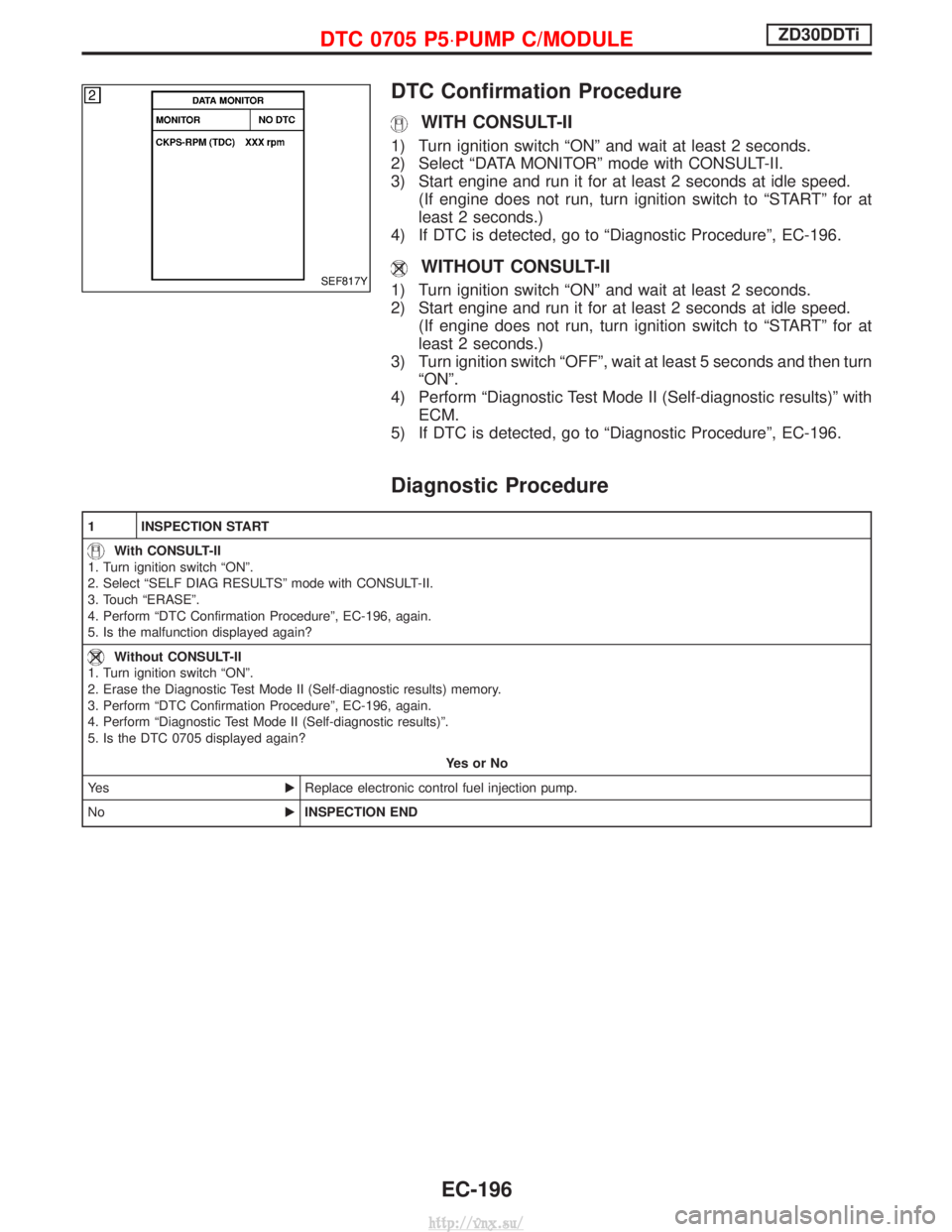
DTC Confirmation Procedure
WITH CONSULT-II
1) Turn ignition switch ªONº and wait at least 2 seconds.
2) Select ªDATA MONITORº mode with CONSULT-II.
3) Start engine and run it for at least 2 seconds at idle speed.(If engine does not run, turn ignition switch to ªSTARTº for at
least 2 seconds.)
4) If DTC is detected, go to ªDiagnostic Procedureº, EC-196.
WITHOUT CONSULT-II
1) Turn ignition switch ªONº and wait at least 2 seconds.
2) Start engine and run it for at least 2 seconds at idle speed. (If engine does not run, turn ignition switch to ªSTARTº for at
least 2 seconds.)
3) Turn ignition switch ªOFFº, wait at least 5 seconds and then turn ªONº.
4) Perform ªDiagnostic Test Mode II (Self-diagnostic results)º with ECM.
5) If DTC is detected, go to ªDiagnostic Procedureº, EC-196.
Diagnostic Procedure
1 INSPECTION START
With CONSULT-II
1. Turn ignition switch ªONº.
2. Select ªSELF DIAG RESULTSº mode with CONSULT-II.
3. Touch ªERASEº.
4. Perform ªDTC Confirmation Procedureº, EC-196, again.
5. Is the malfunction displayed again?
Without CONSULT-II
1. Turn ignition switch ªONº.
2. Erase the Diagnostic Test Mode II (Self-diagnostic results) memory.
3. Perform ªDTC Confirmation Procedureº, EC-196, again.
4. Perform ªDiagnostic Test Mode II (Self-diagnostic results)º.
5. Is the DTC 0705 displayed again?
YesorNo
Ye s EReplace electronic control fuel injection pump.
No EINSPECTION END
SEF817Y
DTC 0705 P5×PUMP C/MODULEZD30DDTi
EC-196
http://vnx.su/
Page 481 of 1833
Diagnostic Procedure
1 INSPECTION START
With CONSULT-II
1. Turn ignition switch ªONº.
2. Select ªSELF DIAG RESULTSº mode with CONSULT-II.
3. Touch ªERASEº.
4. Perform ªDTC Confirmation Procedureº, EC-205, again.
5. Is the malfunction displayed again?
Without CONSULT-II
1. Turn ignition switch ªONº.
2. Erase the Diagnostic Test Mode II (Self-diagnostic results) memory.
3. Perform ªDTC Confirmation Procedureº, EC-205, again.
4. Perform ªDiagnostic Test Mode II (Self-diagnostic results)º.
5. Is the DTC 0802 displayed again?
YesorNo
Ye s EReplace ECM.
No EINSPECTION END
DTC 0802 ECM 10ZD30DDTi
EC-206
http://vnx.su/
Page 483 of 1833
Diagnostic Procedure
1 INSPECTION START
With CONSULT-II
1. Turn ignition switch ªONº.
2. Select ªSELF DIAG RESULTSº mode with CONSULT-II.
3. Touch ªERASEº.
4. Perform ªDTC Confirmation Procedureº, EC-207, again.
5. Is the malfunction displayed again?
Without CONSULT-II
1. Turn ignition switch ªONº.
2. Erase the Diagnostic Test Mode II (Self-diagnostic results) memory.
3. Perform ªDTC Confirmation Procedureº, EC-207, again.
4. Perform ªDiagnostic Test Mode II (Self-diagnostic results)º.
5. Is the DTC 0802 displayed again?
YesorNo
Ye s EReplace ECM.
No EINSPECTION END
DTC 0804 ECM 11ZD30DDTi
EC-208
http://vnx.su/
Page 494 of 1833
Diagnostic Procedure
1 INSPECTION START
With CONSULT-II
1. Turn ignition switch ªONº.
2. Select ªSELF DIAG RESULTSº mode with CONSULT-II.
3. Touch ªERASEº.
4. Perform ªDTC Confirmation Procedureº, EC-218, again.
5. Is the malfunction displayed again?
Without CONSULT-II
1. Turn ignition switch ªONº.
2. Erase the Diagnostic Test Mode II (Self-diagnostic results) memory.
3. Perform ªDTC Confirmation Procedureº, EC-218, again.
4. Perform ªDiagnostic Test Mode II (Self-diagnostic results)º.
5. Is the DTC 0903 displayed again?
YesorNo
Ye s EReplace ECM.
No EINSPECTION END
DTC 0903 ECM 15ZD30DDTi
EC-219
http://vnx.su/
Page 591 of 1833

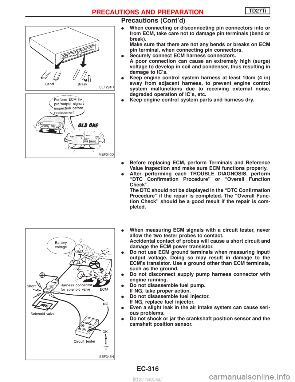
IWhen connecting or disconnecting pin connectors into or
from ECM, take care not to damage pin terminals (bend or
break).
Make sure that there are not any bends or breaks on ECM
pin terminal, when connecting pin connectors.
I Securely connect ECM harness connectors.
A poor connection can cause an extremely high (surge)
voltage to develop in coil and condenser, thus resulting in
damage to IC's.
I Keep engine control system harness at least 10cm (4 in)
away from adjacent harness, to prevent engine control
system malfunctions due to receiving external noise,
degraded operation of IC's, etc.
I Keep engine control system parts and harness dry.
I Before replacing ECM, perform Terminals and Reference
Value inspection and make sure ECM functions properly.
I After performing each TROUBLE DIAGNOSIS, perform
ªDTC Confirmation Procedureº or ªOverall Function
Checkº.
The DTC should not be displayed in the ªDTC Confirmation
Procedureº if the repair is completed. The ªOverall Func-
tion Checkº should be a good result if the repair is com-
pleted.
I When measuring ECM signals with a circuit tester, never
allow the two tester probes to contact.
Accidental contact of probes will cause a short circuit and
damage the ECM power transistor.
I Do not use ECM ground terminals when measuring input/
output voltage. Doing so may result in damage to the
ECM's transistor. Use a ground other than ECM terminals,
such as the ground.
I Do not disconnect supply pump harness connector with
engine running.
I Do not disassemble fuel pump.
If NG, take proper action.
I Do not disassemble fuel injector.
If NG, replace fuel injector.
I Even a slight leak in the air intake system can cause seri-
ous problems.
I Do not shock or jar the crankshaft position sensor and the
camshaft position sensor.
SEF291H
MEF040D
SEF348N
PRECAUTIONS AND PREPARATIONTD27Ti
Precautions (Cont'd)
EC-316
http://vnx.su/