2004 NISSAN TERRANO display
[x] Cancel search: displayPage 635 of 1833
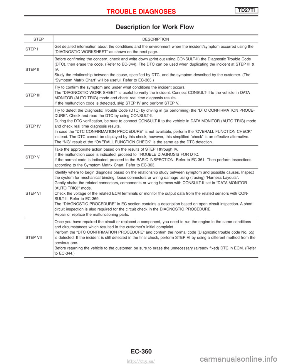
Description for Work Flow
STEPDESCRIPTION
STEP I Get detailed information about the conditions and the environment when the incident/symptom occurred using the
ªDIAGNOSTIC WORKSHEETº as shown on the next page.
STEP II Before confirming the concern, check and write down (print out using CONSULT-II) the Diagnostic Trouble Code
(DTC), then erase the code. (Refer to EC-344). The DTC can be used when duplicating the incident at STEP III &
IV.
Study the relationship between the cause, specified by DTC, and the symptom described by the customer. (The
ªSymptom Matrix Chartº will be useful. Refer to EC-363.)
STEP III Try to confirm the symptom and under what conditions the incident occurs.
The ªDIAGNOSTIC WORK SHEETº is useful to verify the incident. Connect CONSULT-II to the vehicle in DATA
MONITOR (AUTO TRIG) mode and check real time diagnosis results.
If the malfunction code is detected, skip STEP IV and perform STEP V.
STEP IV Try to detect the Diagnostic Trouble Code (DTC) by driving in (or performing) the ªDTC CONFIRMATION PROCE-
DUREº. Check and read the DTC by using CONSULT-II.
During the DTC verification, be sure to connect CONSULT-II to the vehicle in DATA MONITOR (AUTO TRIG) mode
and check real time diagnosis results.
In case the ªDTC CONFIRMATION PROCEDUREº is not available, perform the ªOVERALL FUNCTION CHECKº
instead. The DTC cannot be displayed by this check, however, this simplified ªcheckº is an effective alternative.
The ªNGº result of the ªOVERALL FUNCTION CHECKº is the same as the DTC detection.
STEP V Take the appropriate action based on the results of STEP I through IV.
If the malfunction code is indicated, proceed to TROUBLE DIAGNOSIS FOR DTC.
If the normal code is indicated, proceed to the BASIC INSPECTION. Refer to EC-361. Then perform inspections
according to the Symptom Matrix Chart. Refer to EC-363.
STEP VI Identify where to begin diagnosis based on the relationship study between symptom and possible causes. Inspect
the system for mechanical binding, loose connectors or wiring damage using (tracing) ªHarness Layoutsº.
Gently shake the related connectors, components or wiring harness with CONSULT-II set in ªDATA MONITOR
(AUTO TRIG)º mode.
Check the voltage of the related ECM terminals or monitor the output data from the related sensors with CON-
SULT-II. Refer to EC-369.
The ªDIAGNOSTIC PROCEDUREº in EC section contains a description based on open circuit inspection. A short
circuit inspection is also required for the circuit check in the DIAGNOSTIC PROCEDURE.
Repair or replace the malfunctioning parts.
STEP VII Once you have repaired the circuit or replaced a component, you need to run the engine in the same conditions
and circumstances which resulted in the customer's initial complaint.
Perform the ªDTC CONFIRMATION PROCEDUREº and confirm the normal code (Diagnostic trouble code No. 55)
is detected. If the incident is still detected in the final check, perform STEP VI by using a different method from the
previous one.
Before returning the vehicle to the customer, be sure to erase the unnecessary (already fixed) DTC in ECM. (Refer
to EC-344.)
TROUBLE DIAGNOSESTD27Ti
EC-360
http://vnx.su/
Page 637 of 1833
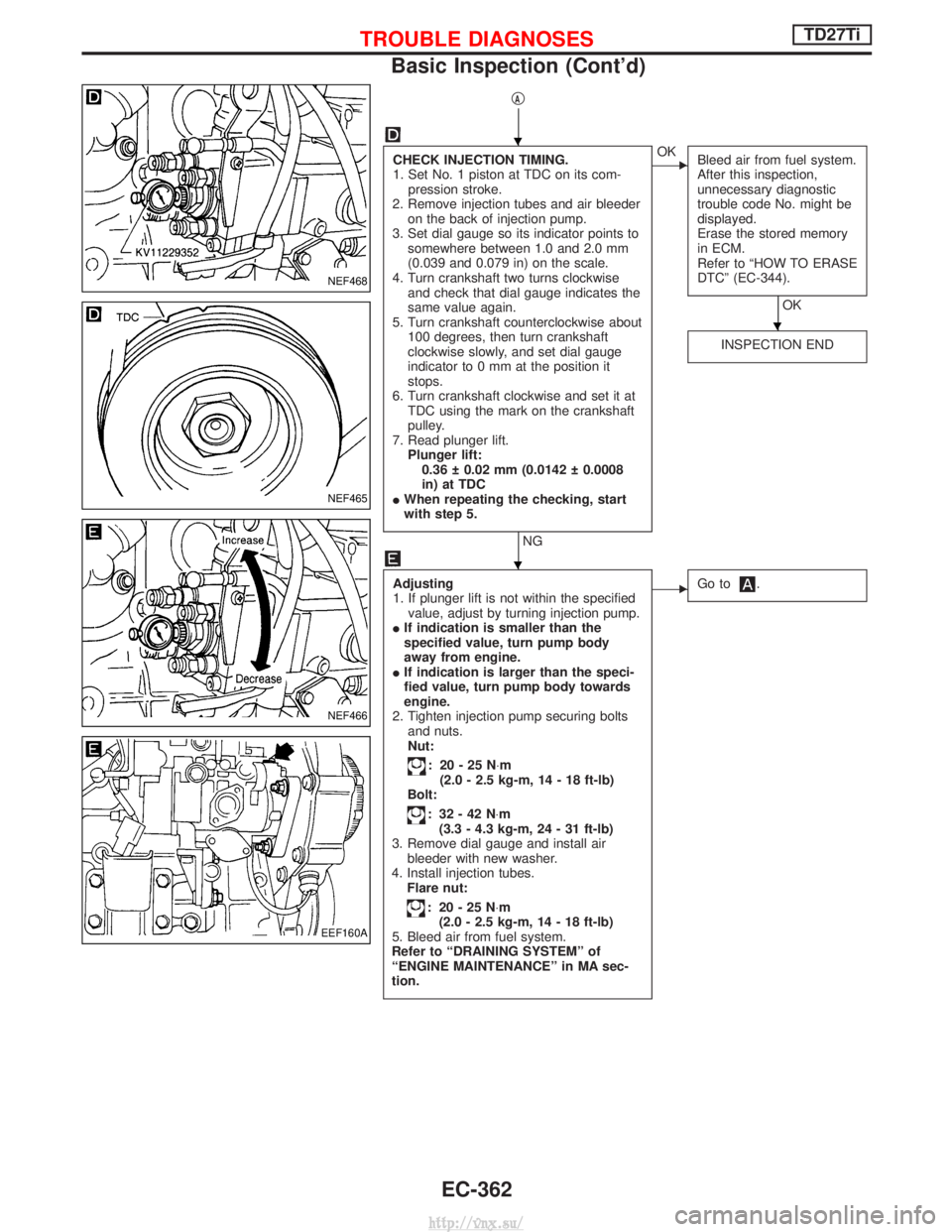
qA
CHECK INJECTION TIMING.
1. Set No. 1 piston at TDC on its com-pression stroke.
2. Remove injection tubes and air bleeder on the back of injection pump.
3. Set dial gauge so its indicator points to somewhere between 1.0 and 2.0 mm
(0.039 and 0.079 in) on the scale.
4. Turn crankshaft two turns clockwise and check that dial gauge indicates the
same value again.
5. Turn crankshaft counterclockwise about 100 degrees, then turn crankshaft
clockwise slowly, and set dial gauge
indicator to 0 mm at the position it
stops.
6. Turn crankshaft clockwise and set it at TDC using the mark on the crankshaft
pulley.
7. Read plunger lift. Plunger lift:0.36 0.02 mm (0.0142 0.0008
in) at TDC
I When repeating the checking, start
with step 5.
NG
EOK
Bleed air from fuel system.
After this inspection,
unnecessary diagnostic
trouble code No. might be
displayed.
Erase the stored memory
in ECM.
Refer to ªHOW TO ERASE
DTCº (EC-344).
OK
INSPECTION END
Adjusting
1. If plunger lift is not within the specified value, adjust by turning injection pump.
I If indication is smaller than the
specified value, turn pump body
away from engine.
I If indication is larger than the speci-
fied value, turn pump body towards
engine.
2. Tighten injection pump securing bolts and nuts.
Nut:
: 20-25N ×m
(2.0 - 2.5 kg-m, 14 - 18 ft-lb)
Bolt:
: 32-42N ×m
(3.3 - 4.3 kg-m, 24 - 31 ft-lb)
3. Remove dial gauge and install air bleeder with new washer.
4. Install injection tubes. Flare nut:
: 20-25N ×m
(2.0 - 2.5 kg-m, 14 - 18 ft-lb)
5. Bleed air from fuel system.
Refer to ªDRAINING SYSTEMº of
ªENGINE MAINTENANCEº in MA sec-
tion.
EGo to.
NEF468
NEF465
NEF466
EEF160A
H
H
H
TROUBLE DIAGNOSESTD27Ti
Basic Inspection (Cont'd)
EC-362
http://vnx.su/
Page 664 of 1833
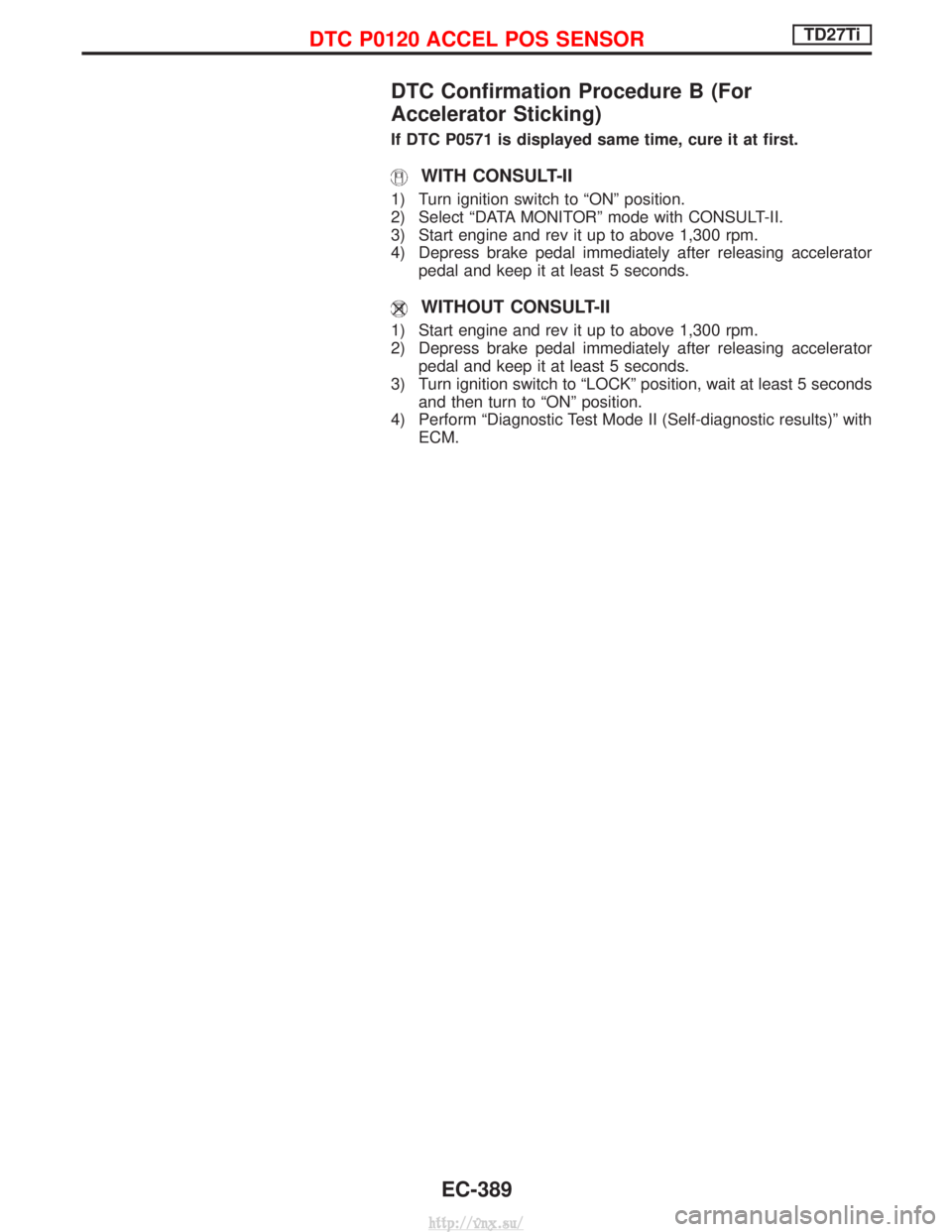
DTC Confirmation Procedure B (For
Accelerator Sticking)
If DTC P0571 is displayed same time, cure it at first.
WITH CONSULT-II
1) Turn ignition switch to ªONº position.
2) Select ªDATA MONITORº mode with CONSULT-II.
3) Start engine and rev it up to above 1,300 rpm.
4) Depress brake pedal immediately after releasing acceleratorpedal and keep it at least 5 seconds.
WITHOUT CONSULT-II
1) Start engine and rev it up to above 1,300 rpm.
2) Depress brake pedal immediately after releasing acceleratorpedal and keep it at least 5 seconds.
3) Turn ignition switch to ªLOCKº position, wait at least 5 seconds and then turn to ªONº position.
4) Perform ªDiagnostic Test Mode II (Self-diagnostic results)º with ECM.
DTC P0120 ACCEL POS SENSORTD27Ti
EC-389
http://vnx.su/
Page 674 of 1833
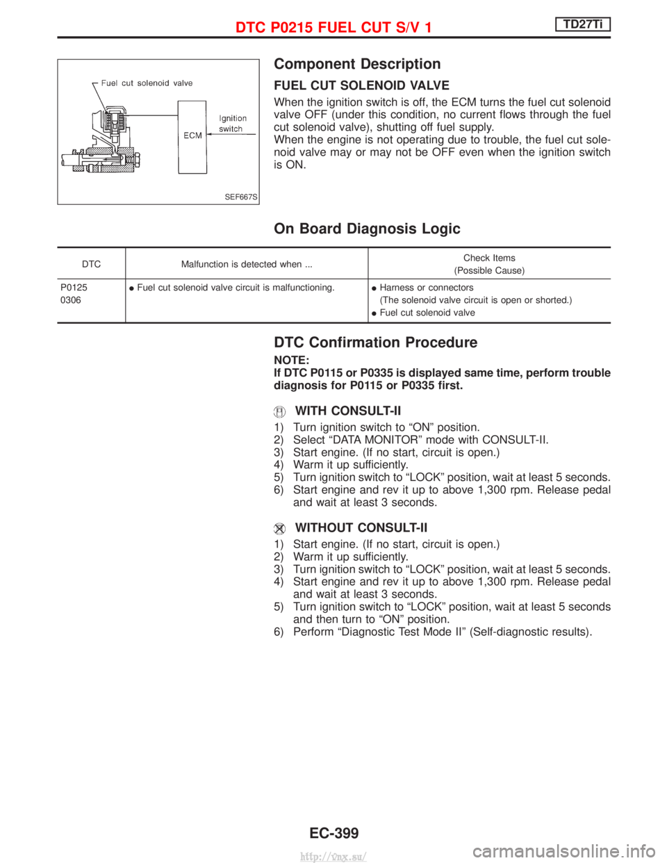
Component Description
FUEL CUT SOLENOID VALVE
When the ignition switch is off, the ECM turns the fuel cut solenoid
valve OFF (under this condition, no current flows through the fuel
cut solenoid valve), shutting off fuel supply.
When the engine is not operating due to trouble, the fuel cut sole-
noid valve may or may not be OFF even when the ignition switch
is ON.
On Board Diagnosis Logic
DTCMalfunction is detected when ... Check Items
(Possible Cause)
P0125
0306 I
Fuel cut solenoid valve circuit is malfunctioning. IHarness or connectors
(The solenoid valve circuit is open or shorted.)
I Fuel cut solenoid valve
DTC Confirmation Procedure
NOTE:
If DTC P0115 or P0335 is displayed same time, perform trouble
diagnosis for P0115 or P0335 first.
WITH CONSULT-II
1) Turn ignition switch to ªONº position.
2) Select ªDATA MONITORº mode with CONSULT-II.
3) Start engine. (If no start, circuit is open.)
4) Warm it up sufficiently.
5) Turn ignition switch to ªLOCKº position, wait at least 5 seconds.
6) Start engine and rev it up to above 1,300 rpm. Release pedal
and wait at least 3 seconds.
WITHOUT CONSULT-II
1) Start engine. (If no start, circuit is open.)
2) Warm it up sufficiently.
3) Turn ignition switch to ªLOCKº position, wait at least 5 seconds.
4) Start engine and rev it up to above 1,300 rpm. Release pedaland wait at least 3 seconds.
5) Turn ignition switch to ªLOCKº position, wait at least 5 seconds and then turn to ªONº position.
6) Perform ªDiagnostic Test Mode IIº (Self-diagnostic results).
SEF667S
DTC P0215 FUEL CUT S/V 1TD27Ti
EC-399
http://vnx.su/
Page 679 of 1833
DTC P1246 Confirmation Procedure
NOTE:
If both DTC P1246 and P1240 or P0335 are displayed, perform
TROUBLE DIAGNOSIS FOR DTC P1240 or P0335. (See EC-450
or EC-408.)
WITH CONSULT-II
1) Turn ignition switch to ªONº position and select ªDATA MONI-TORº mode with CONSULT-II.
2) Start engine. Run it for 10 seconds at idle.
WITHOUT CONSULT-II
1) Start engine. Run it for 10 seconds at idle.
2) Turn ignition switch to ªLOCKº position, wait at least 5 seconds and then turn to ªONº position.
3) Perform ªDiagnostic Test Mode IIº (Self-diagnostic results).
NOTE:
If a malfunction occurs intermittently, conduct suitable driving
pattern for 10 minutes. This makes it possible to determine
DTC.
DTC P0216 INJ TIMING CONT/V, DTC P1246 F/INJ TIMG F/BTD27Ti
EC-404
http://vnx.su/
Page 683 of 1833
Component Description
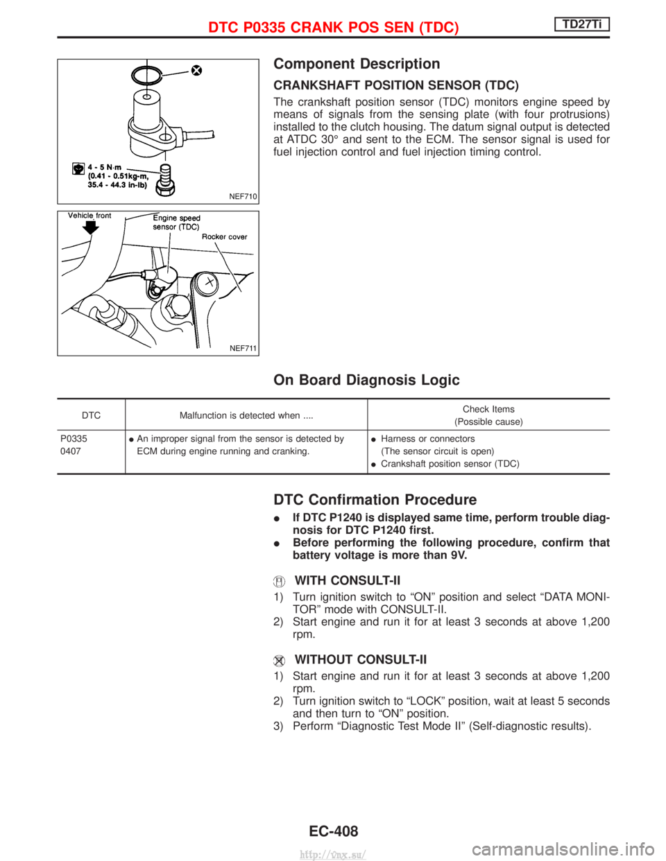
CRANKSHAFT POSITION SENSOR (TDC)
The crankshaft position sensor (TDC) monitors engine speed by
means of signals from the sensing plate (with four protrusions)
installed to the clutch housing. The datum signal output is detected
at ATDC 30É and sent to the ECM. The sensor signal is used for
fuel injection control and fuel injection timing control.
On Board Diagnosis Logic
DTCMalfunction is detected when .... Check Items
(Possible cause)
P0335
0407 I
An improper signal from the sensor is detected by
ECM during engine running and cranking. I
Harness or connectors
(The sensor circuit is open)
I Crankshaft position sensor (TDC)
DTC Confirmation Procedure
I If DTC P1240 is displayed same time, perform trouble diag-
nosis for DTC P1240 first.
I Before performing the following procedure, confirm that
battery voltage is more than 9V.
WITH CONSULT-II
1) Turn ignition switch to ªONº position and select ªDATA MONI-
TORº mode with CONSULT-II.
2) Start engine and run it for at least 3 seconds at above 1,200 rpm.
WITHOUT CONSULT-II
1) Start engine and run it for at least 3 seconds at above 1,200rpm.
2) Turn ignition switch to ªLOCKº position, wait at least 5 seconds and then turn to ªONº position.
3) Perform ªDiagnostic Test Mode IIº (Self-diagnostic results).
NEF710
NEF711
DTC P0335 CRANK POS SEN (TDC)TD27Ti
EC-408
http://vnx.su/
Page 706 of 1833
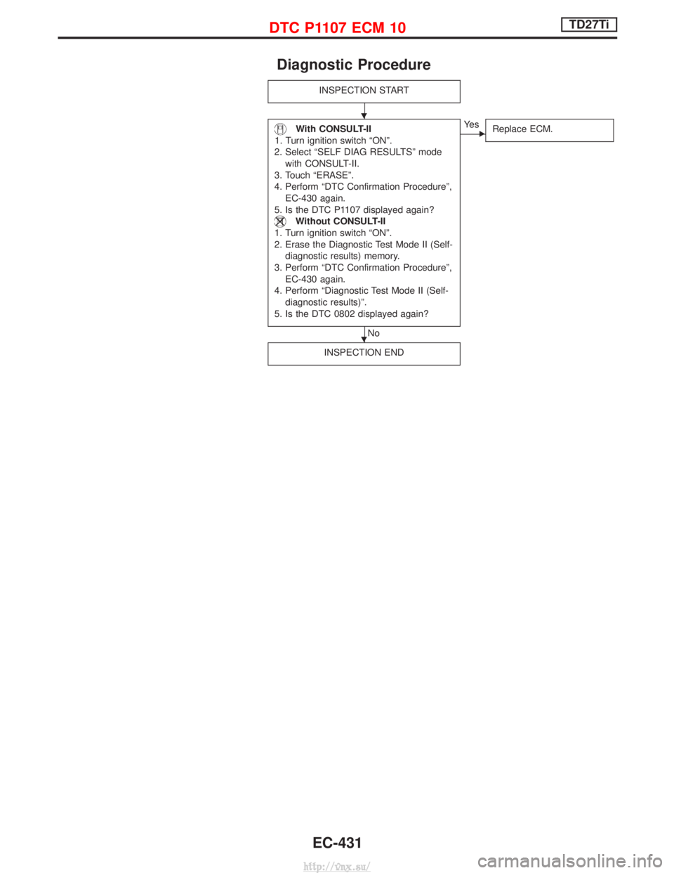
Diagnostic Procedure
INSPECTION START
With CONSULT-II
1. Turn ignition switch ªONº.
2. Select ªSELF DIAG RESULTSº mode with CONSULT-II.
3. Touch ªERASEº.
4. Perform ªDTC Confirmation Procedureº, EC-430 again.
5. Is the DTC P1107 displayed again?
Without CONSULT-II
1. Turn ignition switch ªONº.
2. Erase the Diagnostic Test Mode II (Self- diagnostic results) memory.
3. Perform ªDTC Confirmation Procedureº, EC-430 again.
4. Perform ªDiagnostic Test Mode II (Self- diagnostic results)º.
5. Is the DTC 0802 displayed again?
No
EYe s Replace ECM.
INSPECTION END
H
H
DTC P1107 ECM 10TD27Ti
EC-431
http://vnx.su/
Page 734 of 1833
Diagnostic Procedure
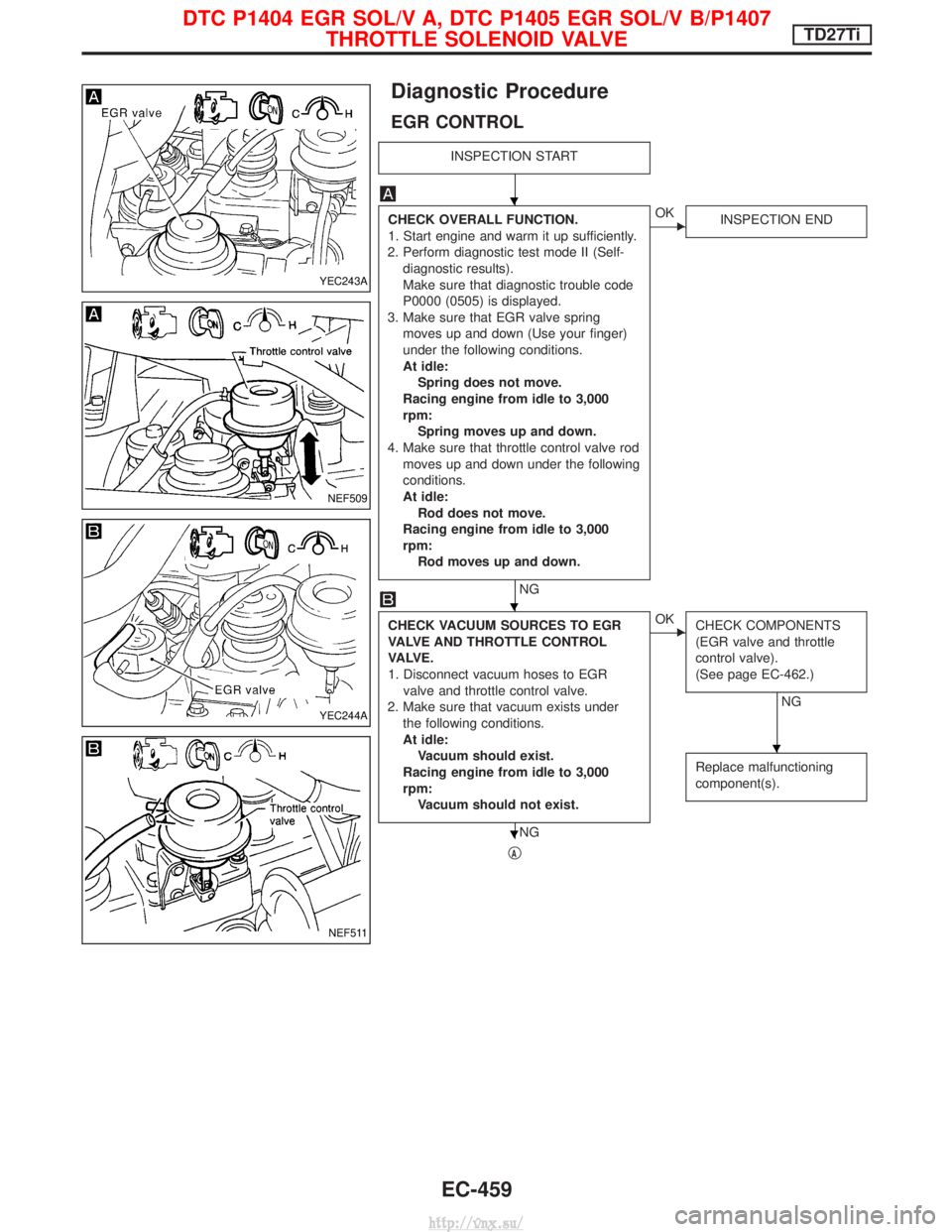
EGR CONTROL
INSPECTION START
CHECK OVERALL FUNCTION.
1. Start engine and warm it up sufficiently.
2. Perform diagnostic test mode II (Self- diagnostic results).
Make sure that diagnostic trouble code
P0000 (0505) is displayed.
3. Make sure that EGR valve spring moves up and down (Use your finger)
under the following conditions.
At idle:Spring does not move.
Racing engine from idle to 3,000
rpm: Spring moves up and down.
4. Make sure that throttle control valve rod moves up and down under the following
conditions.
At idle:Rod does not move.
Racing engine from idle to 3,000
rpm: Rod moves up and down.
NG
EOK INSPECTION END
CHECK VACUUM SOURCES TO EGR
VALVE AND THROTTLE CONTROL
VA LV E .
1. Disconnect vacuum hoses to EGR
valve and throttle control valve.
2. Make sure that vacuum exists under the following conditions.
At idle:Vacuum should exist.
Racing engine from idle to 3,000
rpm: Vacuum should not exist.
NG
EOK CHECK COMPONENTS
(EGR valve and throttle
control valve).
(See page EC-462.)
NG
Replace malfunctioning
component(s).
qA
YEC243A
NEF509
YEC244A
NEF511
H
H
H
H
DTC P1404 EGR SOL/V A, DTC P1405 EGR SOL/V B/P1407 THROTTLE SOLENOID VALVETD27Ti
EC-459
http://vnx.su/