2004 NISSAN TERRANO diagram
[x] Cancel search: diagramPage 20 of 1833
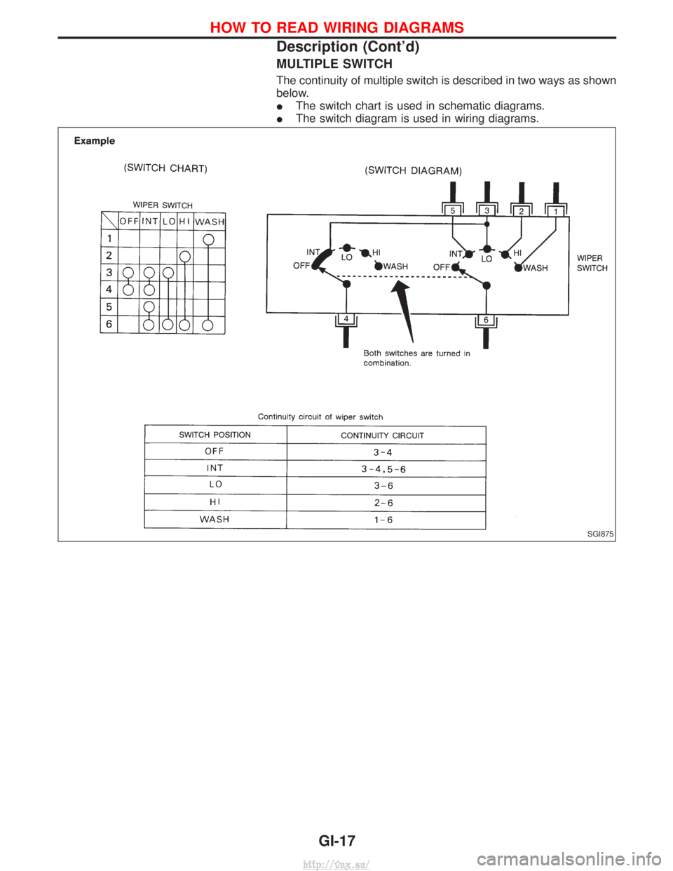
MULTIPLE SWITCH
The continuity of multiple switch is described in two ways as shown
below.
IThe switch chart is used in schematic diagrams.
I The switch diagram is used in wiring diagrams.
SGI875
HOW TO READ WIRING DIAGRAMS
Description (Cont'd)
GI-17
http://vnx.su/
Page 21 of 1833
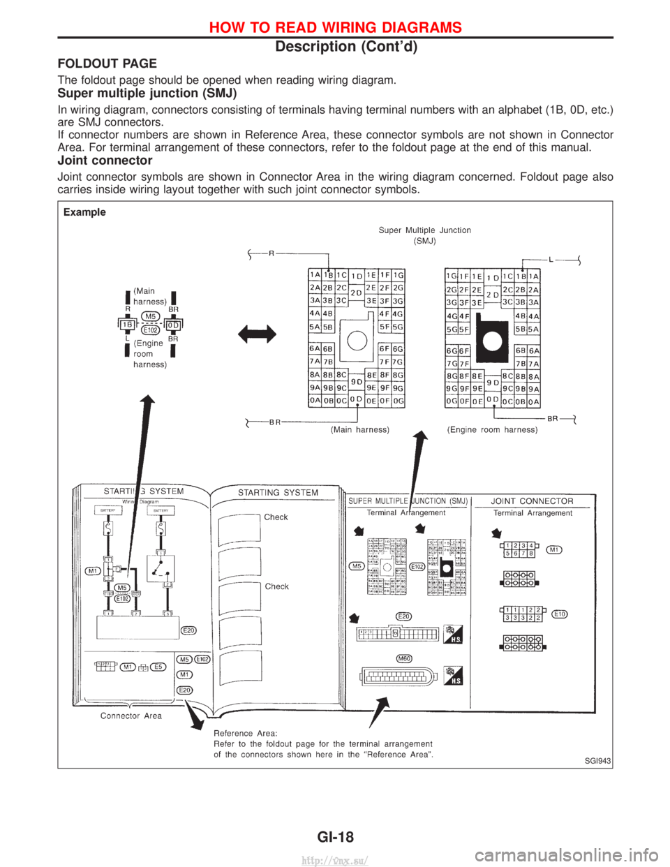
FOLDOUT PAGE
The foldout page should be opened when reading wiring diagram.
Super multiple junction (SMJ)
In wiring diagram, connectors consisting of terminals having terminal numbers with an alphabet (1B, 0D, etc.)
are SMJ connectors.
If connector numbers are shown in Reference Area, these connector symbols are not shown in Connector
Area. For terminal arrangement of these connectors, refer to the foldout page at the end of this manual.
Joint connector
Joint connector symbols are shown in Connector Area in the wiring diagram concerned. Foldout page also
carries inside wiring layout together with such joint connector symbols.
SGI943
HOW TO READ WIRING DIAGRAMS
Description (Cont'd)GI-18
http://vnx.su/
Page 27 of 1833
Engine compartment
There are several reasons a vehicle or engine vibration could
cause an electrical complaint. Some of the things to check for are:
IConnectors not fully seated.
I Wiring harness not long enough and is being stressed due to
engine vibrations or rocking.
I Wires laying across brackets or moving components.
I Loose, dirty or corroded ground wires.
I Wires routed too close to hot components.
To inspect components under the hood, start by verifying the integ-
rity of ground connections. (Refer to GROUND INSPECTION
described later.) First check that the system is properly grounded.
Then check for loose connection by gently shakingthe wiring or
components as previously explained. Using the wiring diagrams
inspect the wiring for continuity.
Behind the instrument panel
An improperly routed or improperly clamped harness can become
pinched during accessory installation. Vehicle vibration can aggra-
vate a harness which is routed along a bracket or near a screw.
Under seating areas
An unclamped or loose harness can cause wiring to be pinched by
seat components (such as slide guides) during vehicle vibration. If
the wiring runs under seating areas, inspect wire routing for pos-
sible damage or pinching.
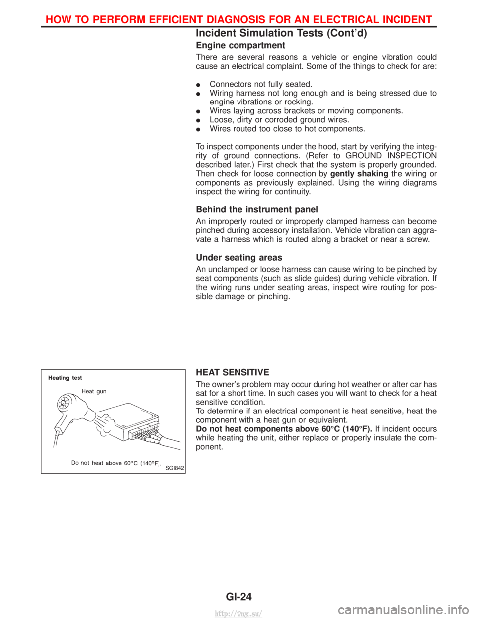
HEAT SENSITIVE
The owner's problem may occur during hot weather or after car has
sat for a short time. In such cases you will want to check for a heat
sensitive condition.
To determine if an electrical component is heat sensitive, heat the
component with a heat gun or equivalent.
Do not heat components above 60ÉC (140ÉF). If incident occurs
while heating the unit, either replace or properly insulate the com-
ponent.
SGI842
HOW TO PERFORM EFFICIENT DIAGNOSIS FOR AN ELECTRICAL INCIDENT
Incident Simulation Tests (Cont'd)
GI-24
http://vnx.su/
Page 110 of 1833
Inspection
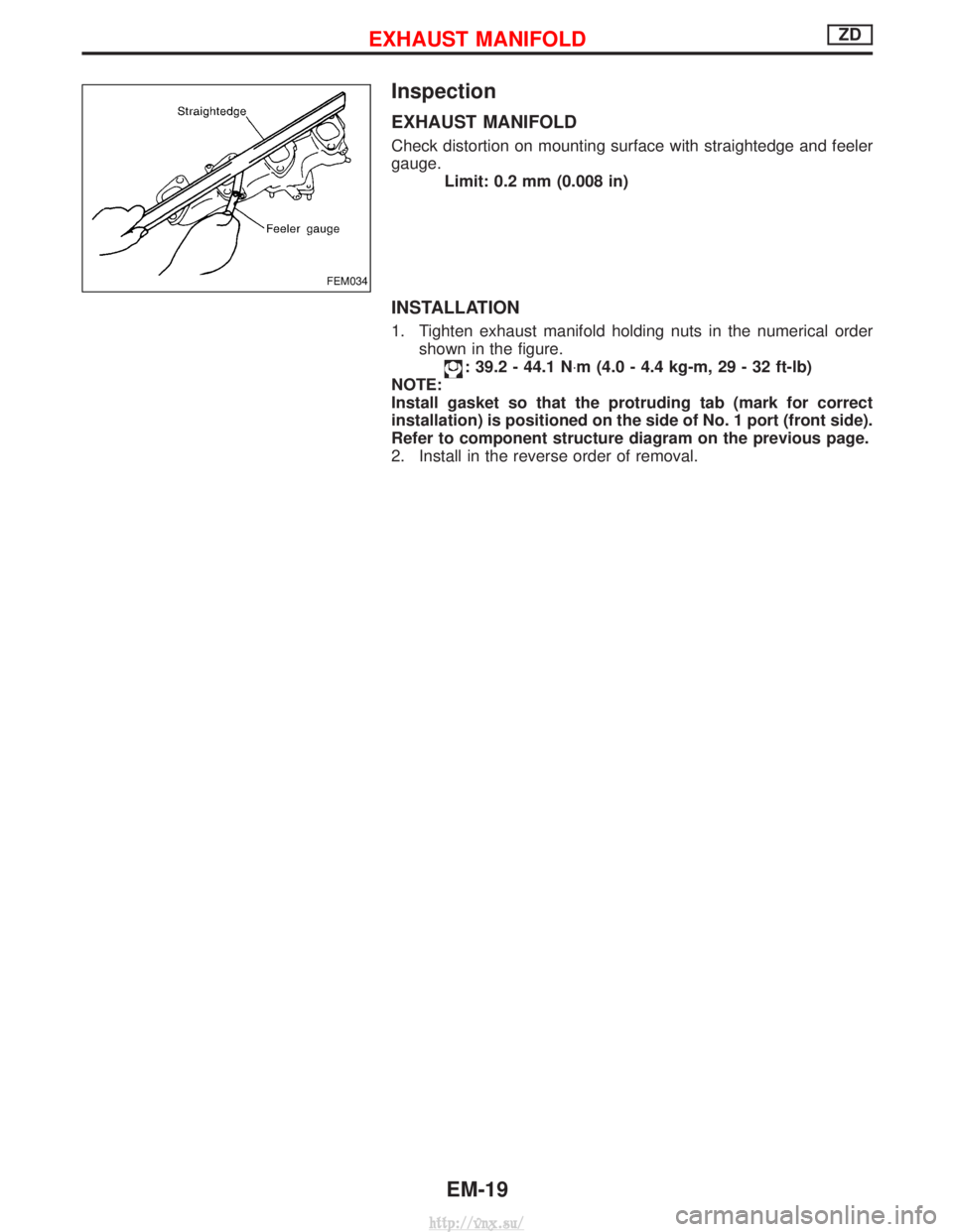
EXHAUST MANIFOLD
Check distortion on mounting surface with straightedge and feeler
gauge.Limit: 0.2 mm (0.008 in)
INSTALLATION
1. Tighten exhaust manifold holding nuts in the numerical ordershown in the figure.
: 39.2 - 44.1 N ×m (4.0 - 4.4 kg-m, 29 - 32 ft-lb)
NOTE:
Install gasket so that the protruding tab (mark for correct
installation) is positioned on the side of No. 1 port (front side).
Refer to component structure diagram on the previous page.
2. Install in the reverse order of removal.
FEM034
EXHAUST MANIFOLDZD
EM-19
http://vnx.su/
Page 276 of 1833
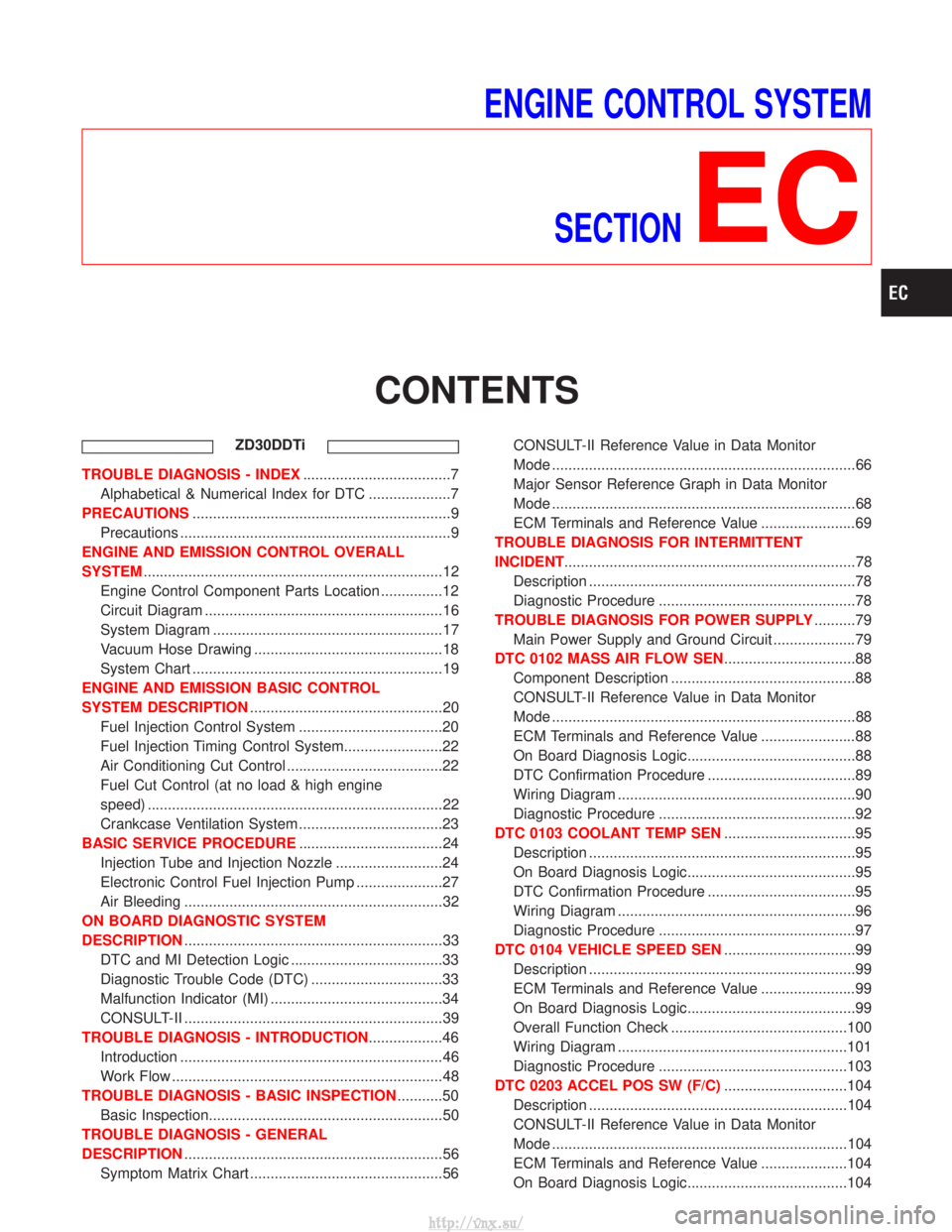
ENGINE CONTROL SYSTEMSECTION
EC
CONTENTS
ZD30DDTi
TROUBLE DIAGNOSIS - INDEX ....................................7
Alphabetical & Numerical Index for DTC ....................7
PRECAUTIONS ...............................................................9
Precautions ..................................................................9
ENGINE AND EMISSION CONTROL OVERALL
SYSTEM ........................................................................\
.12
Engine Control Component Parts Location ...............12
Circuit Diagram ..........................................................16
System Diagram ........................................................17
Vacuum Hose Drawing ..............................................18
System Chart .............................................................19
ENGINE AND EMISSION BASIC CONTROL
SYSTEM DESCRIPTION ...............................................20
Fuel Injection Control System ...................................20
Fuel Injection Timing Control System........................22
Air Conditioning Cut Control ......................................22
Fuel Cut Control (at no load & high engine
speed) ........................................................................\
22
Crankcase Ventilation System ...................................23
BASIC SERVICE PROCEDURE ...................................24
Injection Tube and Injection Nozzle ..........................24
Electronic Control Fuel Injection Pump .....................27
Air Bleeding ...............................................................32
ON BOARD DIAGNOSTIC SYSTEM
DESCRIPTION ...............................................................33
DTC and MI Detection Logic .....................................33
Diagnostic Trouble Code (DTC) ................................33
Malfunction Indicator (MI) ..........................................34
CONSULT-II ...............................................................39
TROUBLE DIAGNOSIS - INTRODUCTION ..................46
Introduction ................................................................46
Work Flow ..................................................................48
TROUBLE DIAGNOSIS - BASIC INSPECTION ...........50
Basic Inspection.........................................................50
TROUBLE DIAGNOSIS - GENERAL
DESCRIPTION ...............................................................56
Symptom Matrix Chart ...............................................56 CONSULT-II Reference Value in Data Monitor
Mode ........................................................................\
..66
Major Sensor Reference Graph in Data Monitor
Mode ........................................................................\
..68
ECM Terminals and Reference Value .......................69
TROUBLE DIAGNOSIS FOR INTERMITTENT
INCIDENT .......................................................................78
Description .................................................................78
Diagnostic Procedure ................................................78
TROUBLE DIAGNOSIS FOR POWER SUPPLY ..........79
Main Power Supply and Ground Circuit ....................79
DTC 0102 MASS AIR FLOW SEN ................................88
Component Description .............................................88
CONSULT-II Reference Value in Data Monitor
Mode ........................................................................\
..88
ECM Terminals and Reference Value .......................88
On Board Diagnosis Logic.........................................88
DTC Confirmation Procedure ....................................89
Wiring Diagram ..........................................................90
Diagnostic Procedure ................................................92
DTC 0103 COOLANT TEMP SEN ................................95
Description .................................................................95
On Board Diagnosis Logic.........................................95
DTC Confirmation Procedure ....................................95
Wiring Diagram ..........................................................96
Diagnostic Procedure ................................................97
DTC 0104 VEHICLE SPEED SEN ................................99
Description .................................................................99
ECM Terminals and Reference Value .......................99
On Board Diagnosis Logic.........................................99
Overall Function Check ...........................................100
Wiring Diagram ........................................................101
Diagnostic Procedure ..............................................103
DTC 0203 ACCEL POS SW (F/C) ..............................104
Description ...............................................................104
CONSULT-II Reference Value in Data Monitor
Mode ........................................................................\
104
ECM Terminals and Reference Value .....................104
On Board Diagnosis Logic.......................................104
http://vnx.su/
Page 277 of 1833
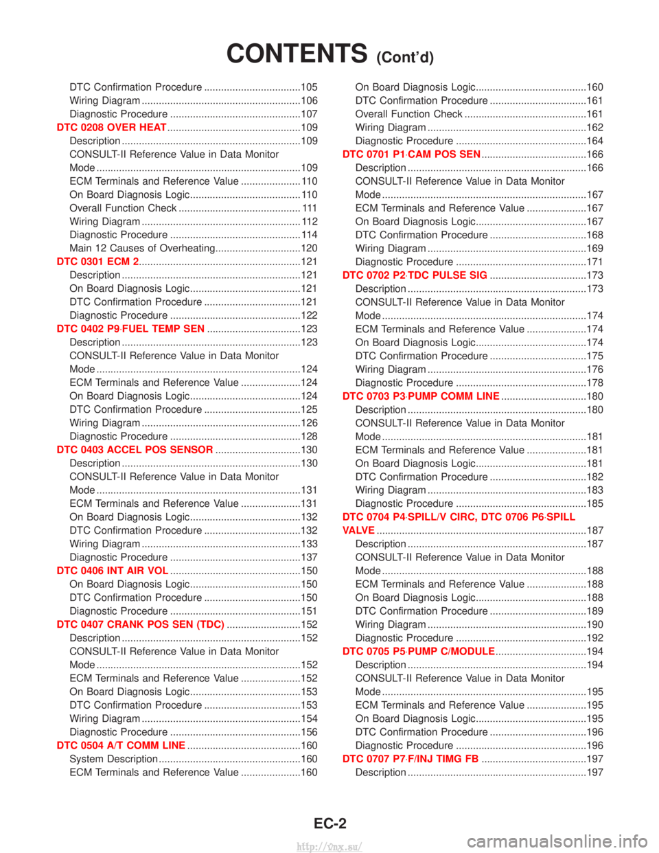
DTC Confirmation Procedure ..................................105
Wiring Diagram ........................................................106
Diagnostic Procedure ..............................................107
DTC 0208 OVER HEAT ...............................................109
Description ...............................................................109
CONSULT-II Reference Value in Data Monitor
Mode ........................................................................\
109
ECM Terminals and Reference Value ..................... 110
On Board Diagnosis Logic....................................... 110
Overall Function Check ........................................... 111
Wiring Diagram ........................................................ 112
Diagnostic Procedure .............................................. 114
Main 12 Causes of Overheating..............................120
DTC 0301 ECM 2.........................................................121 Description ...............................................................121
On Board Diagnosis Logic.......................................121
DTC Confirmation Procedure ..................................121
Diagnostic Procedure ..............................................122
DTC 0402 P9×FUEL TEMP SEN .................................123
Description ...............................................................123
CONSULT-II Reference Value in Data Monitor
Mode ........................................................................\
124
ECM Terminals and Reference Value .....................124
On Board Diagnosis Logic.......................................124
DTC Confirmation Procedure ..................................125
Wiring Diagram ........................................................126
Diagnostic Procedure ..............................................128
DTC 0403 ACCEL POS SENSOR ..............................130
Description ...............................................................130
CONSULT-II Reference Value in Data Monitor
Mode ........................................................................\
131
ECM Terminals and Reference Value .....................131
On Board Diagnosis Logic.......................................132
DTC Confirmation Procedure ..................................132
Wiring Diagram ........................................................133
Diagnostic Procedure ..............................................137
DTC 0406 INT AIR VOL ..............................................150
On Board Diagnosis Logic.......................................150
DTC Confirmation Procedure ..................................150
Diagnostic Procedure ..............................................151
DTC 0407 CRANK POS SEN (TDC) ..........................152
Description ...............................................................152
CONSULT-II Reference Value in Data Monitor
Mode ........................................................................\
152
ECM Terminals and Reference Value .....................152
On Board Diagnosis Logic.......................................153
DTC Confirmation Procedure ..................................153
Wiring Diagram ........................................................154
Diagnostic Procedure ..............................................156
DTC 0504 A/T COMM LINE ........................................160
System Description ..................................................160
ECM Terminals and Reference Value .....................160 On Board Diagnosis Logic.......................................160
DTC Confirmation Procedure ..................................161
Overall Function Check ...........................................161
Wiring Diagram ........................................................162
Diagnostic Procedure ..............................................164
DTC 0701 P1×CAM POS SEN .....................................166
Description ...............................................................166
CONSULT-II Reference Value in Data Monitor
Mode ........................................................................\
167
ECM Terminals and Reference Value .....................167
On Board Diagnosis Logic.......................................167
DTC Confirmation Procedure ..................................168
Wiring Diagram ........................................................169
Diagnostic Procedure ..............................................171
DTC 0702 P2×TDC PULSE SIG ..................................173
Description ...............................................................173
CONSULT-II Reference Value in Data Monitor
Mode ........................................................................\
174
ECM Terminals and Reference Value .....................174
On Board Diagnosis Logic.......................................174
DTC Confirmation Procedure ..................................175
Wiring Diagram ........................................................176
Diagnostic Procedure ..............................................178
DTC 0703 P3×PUMP COMM LINE ..............................180
Description ...............................................................180
CONSULT-II Reference Value in Data Monitor
Mode ........................................................................\
181
ECM Terminals and Reference Value .....................181
On Board Diagnosis Logic.......................................181
DTC Confirmation Procedure ..................................182
Wiring Diagram ........................................................183
Diagnostic Procedure ..............................................185
DTC 0704 P4×SPILL/V CIRC, DTC 0706 P6×SPILL
VA LV E ........................................................................\
..187
Description ...............................................................187
CONSULT-II Reference Value in Data Monitor
Mode ........................................................................\
188
ECM Terminals and Reference Value .....................188
On Board Diagnosis Logic.......................................188
DTC Confirmation Procedure ..................................189
Wiring Diagram ........................................................190
Diagnostic Procedure ..............................................192
DTC 0705 P5×PUMP C/MODULE ................................194
Description ...............................................................194
CONSULT-II Reference Value in Data Monitor
Mode ........................................................................\
195
ECM Terminals and Reference Value .....................195
On Board Diagnosis Logic.......................................195
DTC Confirmation Procedure ..................................196
Diagnostic Procedure ..............................................196
DTC 0707 P7×F/INJ TIMG FB .....................................197
Description ...............................................................197
CONTENTS(Cont'd)
EC-2
http://vnx.su/
Page 278 of 1833
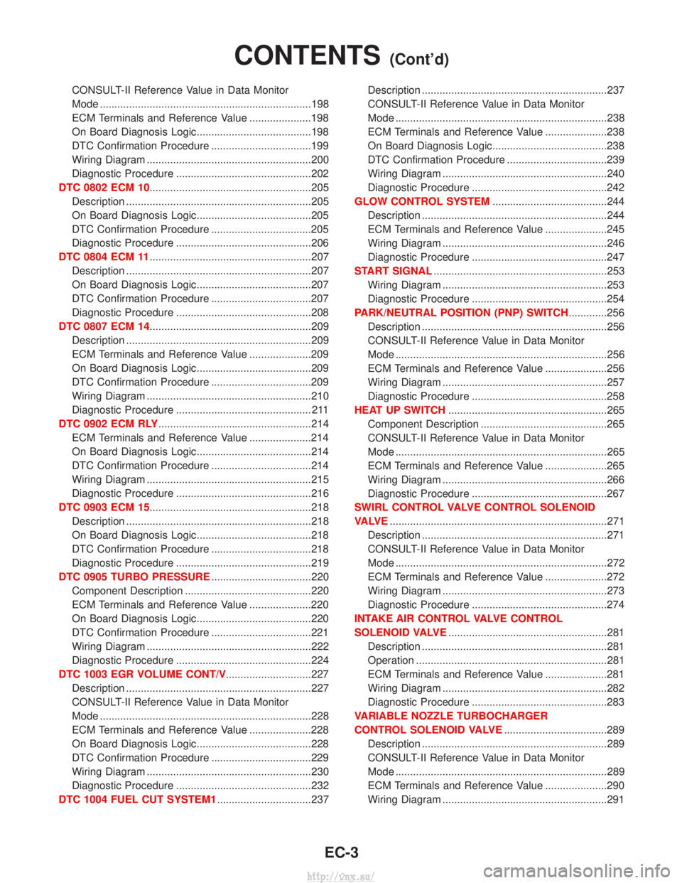
CONSULT-II Reference Value in Data Monitor
Mode ........................................................................\
198
ECM Terminals and Reference Value .....................198
On Board Diagnosis Logic.......................................198
DTC Confirmation Procedure ..................................199
Wiring Diagram ........................................................200
Diagnostic Procedure ..............................................202
DTC 0802 ECM 10.......................................................205 Description ...............................................................205
On Board Diagnosis Logic.......................................205
DTC Confirmation Procedure ..................................205
Diagnostic Procedure ..............................................206
DTC 0804 ECM 11 .......................................................207
Description ...............................................................207
On Board Diagnosis Logic.......................................207
DTC Confirmation Procedure ..................................207
Diagnostic Procedure ..............................................208
DTC 0807 ECM 14.......................................................209 Description ...............................................................209
ECM Terminals and Reference Value .....................209
On Board Diagnosis Logic.......................................209
DTC Confirmation Procedure ..................................209
Wiring Diagram ........................................................210
Diagnostic Procedure .............................................. 211
DTC 0902 ECM RLY ....................................................214
ECM Terminals and Reference Value .....................214
On Board Diagnosis Logic.......................................214
DTC Confirmation Procedure ..................................214
Wiring Diagram ........................................................215
Diagnostic Procedure ..............................................216
DTC 0903 ECM 15.......................................................218 Description ...............................................................218
On Board Diagnosis Logic.......................................218
DTC Confirmation Procedure ..................................218
Diagnostic Procedure ..............................................219
DTC 0905 TURBO PRESSURE ..................................220
Component Description ...........................................220
ECM Terminals and Reference Value .....................220
On Board Diagnosis Logic.......................................220
DTC Confirmation Procedure ..................................221
Wiring Diagram ........................................................222
Diagnostic Procedure ..............................................224
DTC 1003 EGR VOLUME CONT/V .............................227
Description ...............................................................227
CONSULT-II Reference Value in Data Monitor
Mode ........................................................................\
228
ECM Terminals and Reference Value .....................228
On Board Diagnosis Logic.......................................228
DTC Confirmation Procedure ..................................229
Wiring Diagram ........................................................230
Diagnostic Procedure ..............................................232
DTC 1004 FUEL CUT SYSTEM1 ................................237Description ...............................................................237
CONSULT-II Reference Value in Data Monitor
Mode ........................................................................\
238
ECM Terminals and Reference Value .....................238
On Board Diagnosis Logic.......................................238
DTC Confirmation Procedure ..................................239
Wiring Diagram ........................................................240
Diagnostic Procedure ..............................................242
GLOW CONTROL SYSTEM .......................................244
Description ...............................................................244
ECM Terminals and Reference Value .....................245
Wiring Diagram ........................................................246
Diagnostic Procedure ..............................................247
START SIGNAL ...........................................................253
Wiring Diagram ........................................................253
Diagnostic Procedure ..............................................254
PARK/NEUTRAL POSITION (PNP) SWITCH .............256
Description ...............................................................256
CONSULT-II Reference Value in Data Monitor
Mode ........................................................................\
256
ECM Terminals and Reference Value .....................256
Wiring Diagram ........................................................257
Diagnostic Procedure ..............................................258
HEAT UP SWITCH ......................................................265
Component Description ...........................................265
CONSULT-II Reference Value in Data Monitor
Mode ........................................................................\
265
ECM Terminals and Reference Value .....................265
Wiring Diagram ........................................................266
Diagnostic Procedure ..............................................267
SWIRL CONTROL VALVE CONTROL SOLENOID
VA LV E ........................................................................\
..271
Description ...............................................................271
CONSULT-II Reference Value in Data Monitor
Mode ........................................................................\
272
ECM Terminals and Reference Value .....................272
Wiring Diagram ........................................................273
Diagnostic Procedure ..............................................274
INTAKE AIR CONTROL VALVE CONTROL
SOLENOID VALVE ......................................................281
Description ...............................................................281
Operation .................................................................281
ECM Terminals and Reference Value .....................281
Wiring Diagram ........................................................282
Diagnostic Procedure ..............................................283
VARIABLE NOZZLE TURBOCHARGER
CONTROL SOLENOID VALVE ...................................289
Description ...............................................................289
CONSULT-II Reference Value in Data Monitor
Mode ........................................................................\
289
ECM Terminals and Reference Value .....................290
Wiring Diagram ........................................................291
CONTENTS(Cont'd)
EC-3
http://vnx.su/
Page 279 of 1833
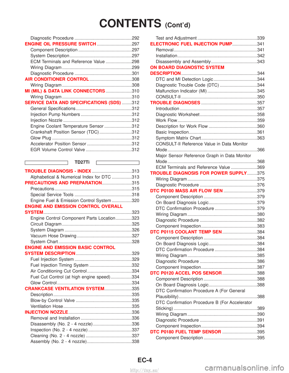
Diagnostic Procedure ..............................................292
ENGINE OIL PRESSURE SWITCH ............................297
Component Description ...........................................297
System Description ..................................................297
ECM Terminals and Reference Value .....................298
Wiring Diagram ........................................................299
Diagnostic Procedure ..............................................301
AIR CONDITIONER CONTROL ..................................308
Wiring Diagram ........................................................308
MI (MIL) & DATA LINK CONNECTORS .....................310
Wiring Diagram ........................................................310
SERVICE DATA AND SPECIFICATIONS (SDS) ........312
General Specifications .............................................312
Injection Pump Numbers .........................................312
Injection Nozzle .......................................................312
Engine Coolant Temperature Sensor ......................312
Crankshaft Position Sensor (TDC) ..........................312
Glow Plug ................................................................312
Accelerator Position Sensor ....................................312
EGR Volume Control Valve .....................................312
TD27Ti
TROUBLE DIAGNOSIS - INDEX ................................313
Alphabetical & Numerical Index for DTC ................313
PRECAUTIONS AND PREPARATION ........................315
Precautions ..............................................................315
Special Service Tools ..............................................318
Engine Fuel & Emission Control System ................320
ENGINE AND EMISSION CONTROL OVERALL
SYSTEM .......................................................................323
Engine Control Component Parts Location .............323
Circuit Diagram ........................................................325
System Diagram ......................................................326
Vacuum Hose Drawing ............................................327
System Chart ...........................................................328
ENGINE AND EMISSION BASIC CONTROL
SYSTEM DESCRIPTION .............................................329
Fuel Injection System ..............................................329
Fuel Injection Timing System ..................................332
Air Conditioning Cut Control ....................................334
Fuel Cut Control (at high engine speed) .................334
Glow Control ............................................................334
CRANKCASE VENTILATION SYSTEM ......................335
Description ...............................................................335
Blow-by Control Valve .............................................335
Ventilation Hose .......................................................335
INJECTION NOZZLE ...................................................336
Removal and Installation .........................................336
Disassembly (No.2-4 nozzle) ...............................336
Inspection (No.2-4 nozzle) ...................................337
Cleaning (No.2-4 nozzle) .....................................337
Assembly (No.2-4 nozzle) ....................................338 Test and Adjustment ................................................339
ELECTRONIC FUEL INJECTION PUMP ....................341
Removal ...................................................................341
Installation ................................................................342
Disassembly and Assembly .....................................343
ON BOARD DIAGNOSTIC SYSTEM
DESCRIPTION .............................................................344
DTC and MI Detection Logic ...................................344
Diagnostic Trouble Code (DTC) ..............................344
Malfunction Indicator (MI) ........................................345
CONSULT-II .............................................................350
TROUBLE DIAGNOSES .............................................357
Introduction ..............................................................357
Diagnostic Worksheet ..............................................358
Work Flow ................................................................359
Description for Work Flow .......................................360
Basic Inspection.......................................................361
Symptom Matrix Chart .............................................363
CONSULT-II Reference Value in Data Monitor
Mode ........................................................................\
366
Major Sensor Reference Graph in Data Monitor
Mode ........................................................................\
368
ECM Terminals and Reference Value .....................369
TROUBLE DIAGNOSIS FOR POWER SUPPLY ........375
Wiring Diagram ........................................................375
Diagnostic Procedure ..............................................376
DTC P0100 MASS AIR FLOW SEN ...........................379
Component Description ...........................................379
On Board Diagnosis Logic.......................................379
DTC Confirmation Procedure ..................................379
Wiring Diagram ........................................................380
Diagnostic Procedure ..............................................382
Component Inspection .............................................383
DTC P0115 COOLANT TEMP SEN ............................384
Component Description ...........................................384
On Board Diagnosis Logic.......................................384
DTC Confirmation Procedure ..................................384
Wiring Diagram ........................................................385
Diagnostic Procedure ..............................................386
Component Inspection .............................................387
DTC P0120 ACCEL POS SENSOR ............................388
Component Description ...........................................388
On Board Diagnosis Logic.......................................388
DTC Confirmation Procedure A (For General
Plausibility) ...............................................................388
DTC Confirmation Procedure B (For Accelerator
Sticking) ...................................................................389
Wiring Diagram ........................................................390
Diagnostic Procedure ..............................................391
Component Inspection .............................................394
DTC P0180 FUEL TEMP SENSOR ............................395
Component Description ...........................................395
CONTENTS(Cont'd)
EC-4
http://vnx.su/