2004 NISSAN TERRANO diagram
[x] Cancel search: diagramPage 280 of 1833
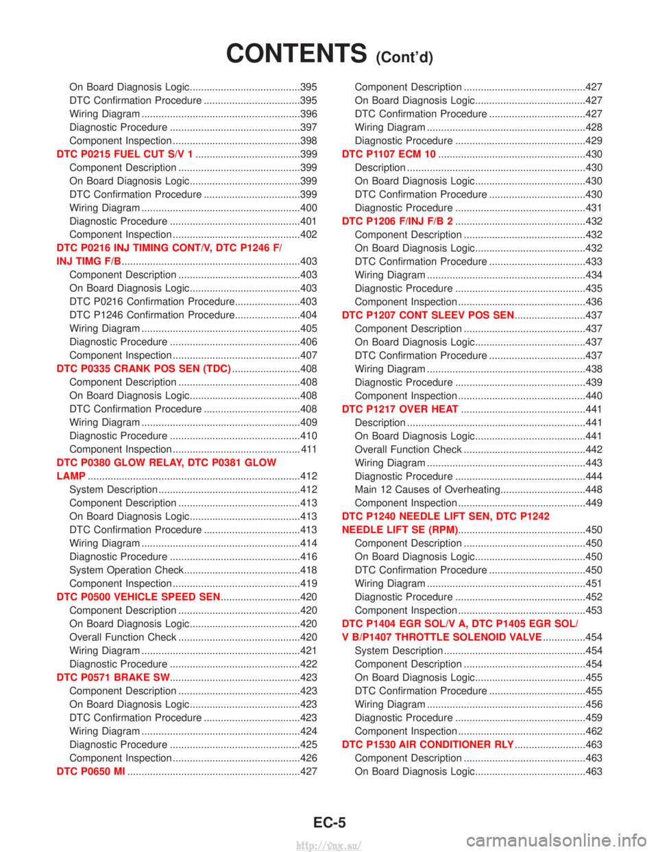
On Board Diagnosis Logic.......................................395
DTC Confirmation Procedure ..................................395
Wiring Diagram ........................................................396
Diagnostic Procedure ..............................................397
Component Inspection .............................................398
DTC P0215 FUEL CUT S/V 1 .....................................399
Component Description ...........................................399
On Board Diagnosis Logic.......................................399
DTC Confirmation Procedure ..................................399
Wiring Diagram ........................................................400
Diagnostic Procedure ..............................................401
Component Inspection .............................................402
DTC P0216 INJ TIMING CONT/V, DTC P1246 F/
INJ TIMG F/B ...............................................................403
Component Description ...........................................403
On Board Diagnosis Logic.......................................403
DTC P0216 Confirmation Procedure.......................403
DTC P1246 Confirmation Procedure.......................404
Wiring Diagram ........................................................405
Diagnostic Procedure ..............................................406
Component Inspection .............................................407
DTC P0335 CRANK POS SEN (TDC) ........................408
Component Description ...........................................408
On Board Diagnosis Logic.......................................408
DTC Confirmation Procedure ..................................408
Wiring Diagram ........................................................409
Diagnostic Procedure ..............................................410
Component Inspection ............................................. 411
DTC P0380 GLOW RELAY, DTC P0381 GLOW
LAMP ........................................................................\
...412
System Description ..................................................412
Component Description ...........................................413
On Board Diagnosis Logic.......................................413
DTC Confirmation Procedure ..................................413
Wiring Diagram ........................................................414
Diagnostic Procedure ..............................................416
System Operation Check.........................................418
Component Inspection .............................................419
DTC P0500 VEHICLE SPEED SEN ............................420
Component Description ...........................................420
On Board Diagnosis Logic.......................................420
Overall Function Check ...........................................420
Wiring Diagram ........................................................421
Diagnostic Procedure ..............................................422
DTC P0571 BRAKE SW ..............................................423
Component Description ...........................................423
On Board Diagnosis Logic.......................................423
DTC Confirmation Procedure ..................................423
Wiring Diagram ........................................................424
Diagnostic Procedure ..............................................425
Component Inspection .............................................426
DTC P0650 MI .............................................................427 Component Description ...........................................427
On Board Diagnosis Logic.......................................427
DTC Confirmation Procedure ..................................427
Wiring Diagram ........................................................428
Diagnostic Procedure ..............................................429
DTC P1107 ECM 10 ....................................................430
Description ...............................................................430
On Board Diagnosis Logic.......................................430
DTC Confirmation Procedure ..................................430
Diagnostic Procedure ..............................................431
DTC P1206 F/INJ F/B 2 ..............................................432
Component Description ...........................................432
On Board Diagnosis Logic.......................................432
DTC Confirmation Procedure ..................................433
Wiring Diagram ........................................................434
Diagnostic Procedure ..............................................435
Component Inspection .............................................436
DTC P1207 CONT SLEEV POS SEN .........................437
Component Description ...........................................437
On Board Diagnosis Logic.......................................437
DTC Confirmation Procedure ..................................437
Wiring Diagram ........................................................438
Diagnostic Procedure ..............................................439
Component Inspection .............................................440
DTC P1217 OVER HEAT ............................................441
Description ...............................................................441
On Board Diagnosis Logic.......................................441
Overall Function Check ...........................................442
Wiring Diagram ........................................................443
Diagnostic Procedure ..............................................444
Main 12 Causes of Overheating..............................448
Component Inspection .............................................449
DTC P1240 NEEDLE LIFT SEN, DTC P1242
NEEDLE LIFT SE (RPM) .............................................450
Component Description ...........................................450
On Board Diagnosis Logic.......................................450
DTC Confirmation Procedure ..................................450
Wiring Diagram ........................................................451
Diagnostic Procedure ..............................................452
Component Inspection .............................................453
DTC P1404 EGR SOL/V A, DTC P1405 EGR SOL/
V B/P1407 THROTTLE SOLENOID VALVE ...............454
System Description ..................................................454
Component Description ...........................................454
On Board Diagnosis Logic.......................................455
DTC Confirmation Procedure ..................................455
Wiring Diagram ........................................................456
Diagnostic Procedure ..............................................459
Component Inspection .............................................462
DTC P1530 AIR CONDITIONER RLY .........................463
Component Description ...........................................463
On Board Diagnosis Logic.......................................463
CONTENTS(Cont'd)
EC-5
http://vnx.su/
Page 281 of 1833
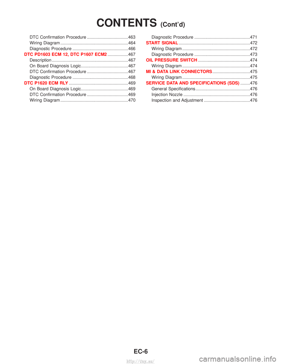
DTC Confirmation Procedure ..................................463
Wiring Diagram ........................................................464
Diagnostic Procedure ..............................................466
DTC PD1603 ECM 12, DTC P1607 ECM2 .................467
Description ...............................................................467
On Board Diagnosis Logic.......................................467
DTC Confirmation Procedure ..................................467
Diagnostic Procedure ..............................................468
DTC P1620 ECM RLY .................................................469
On Board Diagnosis Logic.......................................469
DTC Confirmation Procedure ..................................469
Wiring Diagram ........................................................470 Diagnostic Procedure ..............................................471
START SIGNAL ...........................................................472
Wiring Diagram ........................................................472
Diagnostic Procedure ..............................................473
OIL PRESSURE SWITCH ...........................................474
Wiring Diagram ........................................................474
MI & DATA LINK CONNECTORS ...............................475
Wiring Diagram ........................................................475
SERVICE DATA AND SPECIFICATIONS (SDS) ........476
General Specifications .............................................476
Injection Nozzle .......................................................476
Inspection and Adjustment ......................................476
CONTENTS(Cont'd)
EC-6
http://vnx.su/
Page 291 of 1833
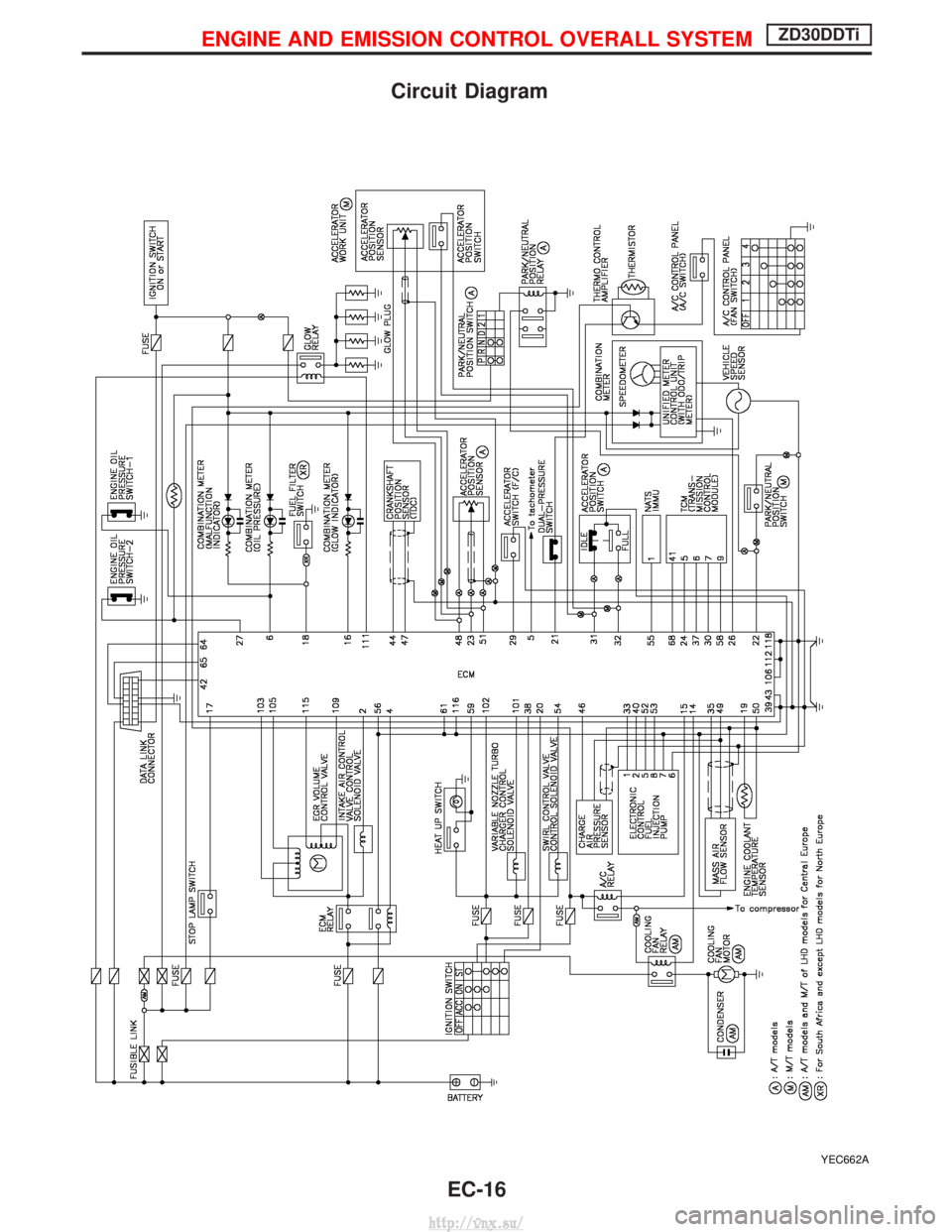
Circuit Diagram
YEC662A
ENGINE AND EMISSION CONTROL OVERALL SYSTEMZD30DDTi
EC-16
http://vnx.su/
Page 292 of 1833
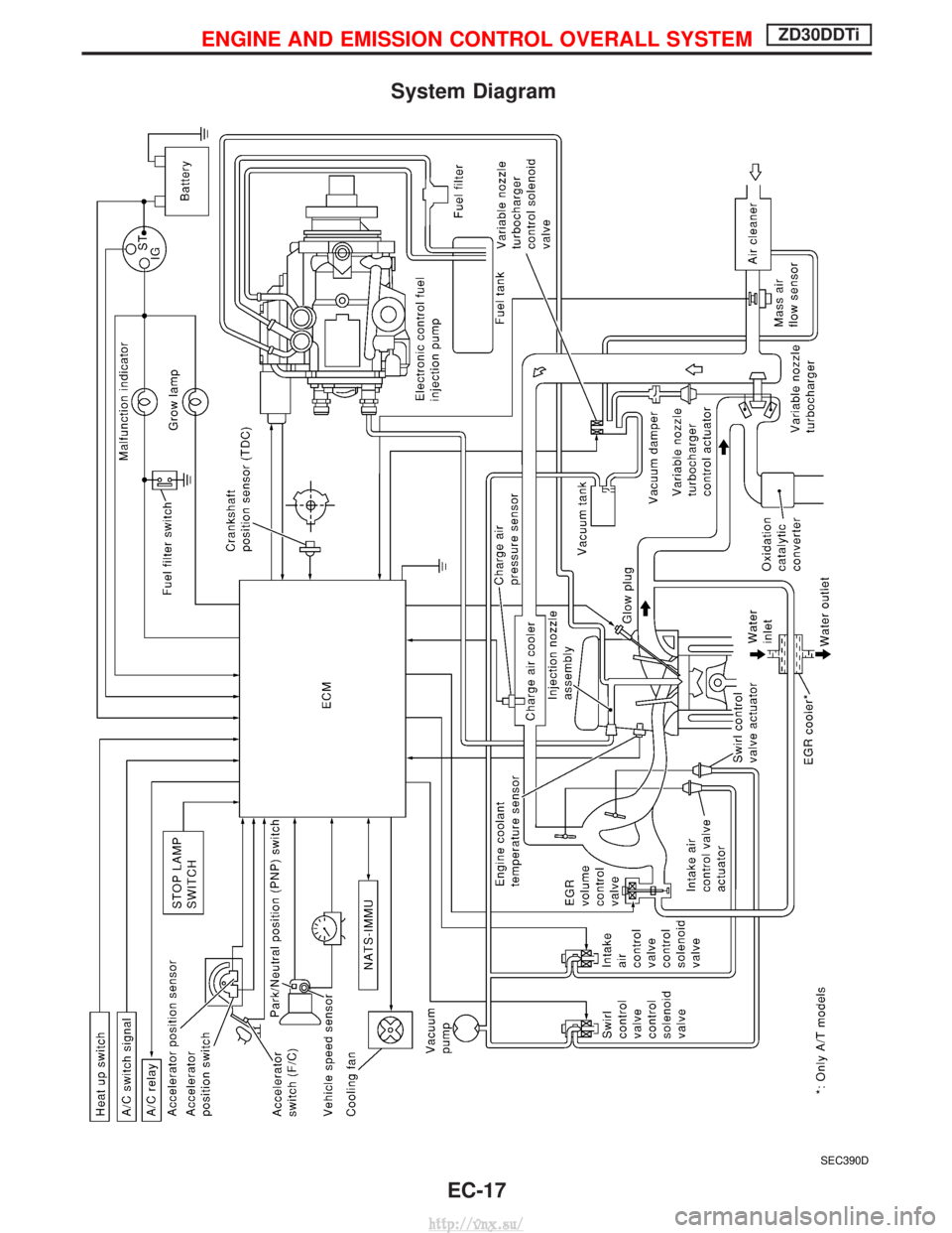
System Diagram
SEC390D
ENGINE AND EMISSION CONTROL OVERALL SYSTEMZD30DDTi
EC-17
http://vnx.su/
Page 293 of 1833

Vacuum Hose Drawing
1. Swirl control valve control solenoidvalve to swirl control valve actua-
tor
2. Intake air control valve control solenoid valve to intake air control
valve actuator 3. Variable nozzle turbocharger con-
trol actuator to vacuum damper
4. Variable nozzle turbocharger con- trol solenoid valve to resonator 5. Variable nozzle turbocharger con-
trol solenoid valve to vacuum
pump
Refer to ªSystem Diagramº, EC-17 for vacuum control system.
MEC030E
ENGINE AND EMISSION CONTROL OVERALL SYSTEMZD30DDTi
EC-18
http://vnx.su/
Page 355 of 1833

WIRING DIAGRAM
YEC171A
TROUBLE DIAGNOSIS FOR POWER SUPPLYZD30DDTi
Main Power Supply and Ground Circuit
(Cont'd)EC-80
http://vnx.su/
Page 357 of 1833
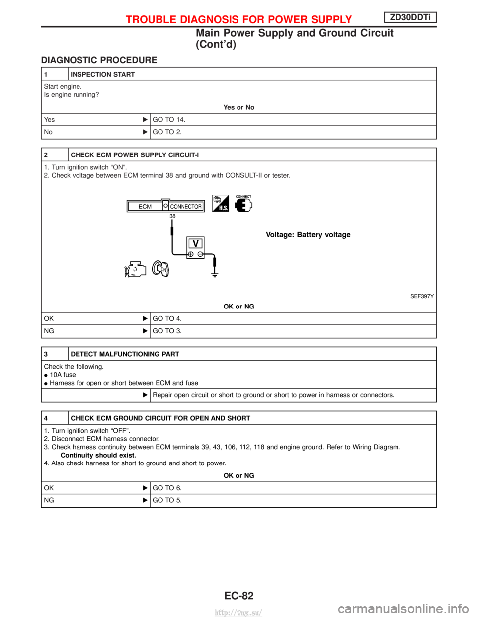
DIAGNOSTIC PROCEDURE
1 INSPECTION START
Start engine.
Is engine running?YesorNo
Ye s EGO TO 14.
No EGO TO 2.
2 CHECK ECM POWER SUPPLY CIRCUIT-I
1. Turn ignition switch ªONº.
2. Check voltage between ECM terminal 38 and ground with CONSULT-II or tester.
SEF397Y
OK or NG
OK EGO TO 4.
NG EGO TO 3.
3 DETECT MALFUNCTIONING PART
Check the following.
I10A fuse
I Harness for open or short between ECM and fuse
ERepair open circuit or short to ground or short to power in harness or connectors.
4 CHECK ECM GROUND CIRCUIT FOR OPEN AND SHORT
1. Turn ignition switch ªOFFº.
2. Disconnect ECM harness connector.
3. Check harness continuity between ECM terminals 39, 43, 106, 112, 118 and engine ground. Refer to Wiring Diagram.
Continuity should exist.
4. Also check harness for short to ground and short to power.
OK or NG
OK EGO TO 6.
NG EGO TO 5.
TROUBLE DIAGNOSIS FOR POWER SUPPLYZD30DDTi
Main Power Supply and Ground Circuit
(Cont'd)
EC-82
http://vnx.su/
Page 359 of 1833
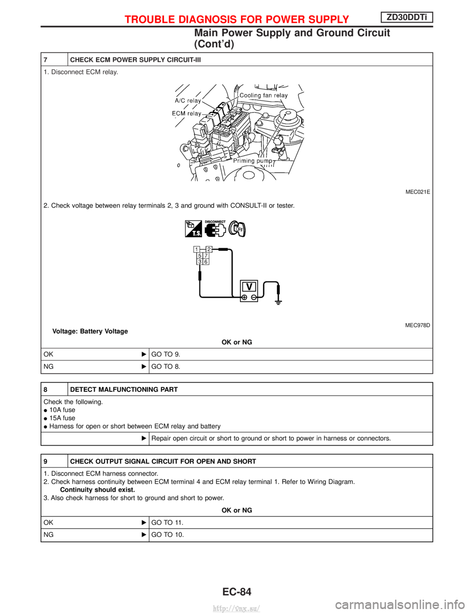
7 CHECK ECM POWER SUPPLY CIRCUIT-III
1. Disconnect ECM relay.
MEC021E
2. Check voltage between relay terminals 2, 3 and ground with CONSULT-II or tester.
MEC978DVoltage: Battery VoltageOK or NG
OK EGO TO 9.
NG EGO TO 8.
8 DETECT MALFUNCTIONING PART
Check the following.
I10A fuse
I 15A fuse
I Harness for open or short between ECM relay and battery
ERepair open circuit or short to ground or short to power in harness or connectors.
9 CHECK OUTPUT SIGNAL CIRCUIT FOR OPEN AND SHORT
1. Disconnect ECM harness connector.
2. Check harness continuity between ECM terminal 4 and ECM relay terminal 1. Refer to Wiring Diagram.
Continuity should exist.
3. Also check harness for short to ground and short to power.
OK or NG
OK EGO TO 11.
NG EGO TO 10.
TROUBLE DIAGNOSIS FOR POWER SUPPLYZD30DDTi
Main Power Supply and Ground Circuit
(Cont'd)
EC-84
http://vnx.su/