2004 NISSAN TERRANO wheel alignment
[x] Cancel search: wheel alignmentPage 44 of 1833
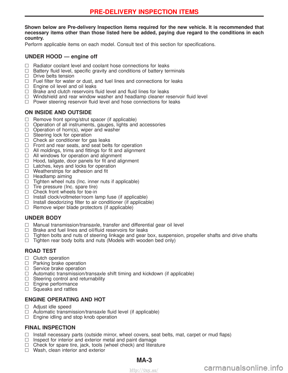
Shown below are Pre-delivery Inspection items required for the new vehicle. It is recommended that
necessary items other than those listed here be added, paying due regard to the conditions in each
country.
Perform applicable items on each model. Consult text of this section for specifications.
UNDER HOOD Ð engine off
lRadiator coolant level and coolant hose connections for leaks
l Battery fluid level, specific gravity and conditions of battery terminals
l Drive belts tension
l Fuel filter for water or dust, and fuel lines and connections for leaks
l Engine oil level and oil leaks
l Brake and clutch reservoirs fluid level and fluid lines for leaks
l Windshield and rear window washer and headlamp cleaner reservoir fluid level
l Power steering reservoir fluid level and hose connections for leaks
ON INSIDE AND OUTSIDE
lRemove front spring/strut spacer (if applicable)
l Operation of all instruments, gauges, lights and accessories
l Operation of horn(s), wiper and washer
l Steering lock for operation
l Check air conditioner for gas leaks
l Front and rear seats, and seat belts for operation
l All moldings, trims and fittings for fit and alignment
l All windows for operation and alignment
l Hood, tailgate, door panels for fit and alignment
l Latches, keys and locks for operation
l Weatherstrips for adhesion and fit
l Headlamp aiming
l Tighten wheel nuts (Inc. inner nuts if applicable)
l Tire pressure (Inc. spare tire)
l Check front wheels for toe-in
l Install clock/voltmeter/room lamp fuse (if applicable)
l Install deodorizing filter to air conditioner (if applicable)
l Remove wiper blade protectors (if applicable)
UNDER BODY
lManual transmission/transaxle, transfer and differential gear oil level
l Brake and fuel lines and oil/fluid reservoirs for leaks
l Tighten bolts and nuts of steering linkage and gear box, suspension, propeller shafts and drive shafts
l Tighten rear body bolts and nuts (Models with wooden bed only)
ROAD TEST
lClutch operation
l Parking brake operation
l Service brake operation
l Automatic transmission/transaxle shift timing and kickdown (if applicable)
l Steering control and returnability
l Engine performance
l Squeaks and rattles
ENGINE OPERATING AND HOT
lAdjust idle speed
l Automatic transmission/transaxle fluid level (if applicable)
l Engine idling and stop knob operation
FINAL INSPECTION
lInstall necessary parts (outside mirror, wheel covers, seat belts, mat, carpet or mud flaps)
l Inspect for interior and exterior metal and paint damage
l Check for spare tire, jack, tools (wheel check) and literature
l Wash, clean interior and exterior
PRE-DELIVERY INSPECTION ITEMS
MA-3
http://vnx.su/
Page 48 of 1833
![NISSAN TERRANO 2004 Service Repair Manual Chassis and Body Maintenance
Abbreviations: R = Replace I = Inspect. Correct or replace if necessary L = Lubricate T = Tighten[ ] = At the specified mileage only
MAINTENANCE OPERATION MAINTENANCE INTE NISSAN TERRANO 2004 Service Repair Manual Chassis and Body Maintenance
Abbreviations: R = Replace I = Inspect. Correct or replace if necessary L = Lubricate T = Tighten[ ] = At the specified mileage only
MAINTENANCE OPERATION MAINTENANCE INTE](/manual-img/5/57394/w960_57394-47.png)
Chassis and Body Maintenance
Abbreviations: R = Replace I = Inspect. Correct or replace if necessary L = Lubricate T = Tighten[ ] = At the specified mileage only
MAINTENANCE OPERATION MAINTENANCE INTERVAL
Refer-ence
page
Perform on a kilometer basis, but on
a semi-annual basis when driving
less than 20,000 km (12,000 miles)
per year. km x 1,000 10 20 30 40 50 60 70 80 90 100 110 120
(miles x 1,000) (6) (12) (18) (24) (30) (36) (42) (48) (54) (60) (66) (72)
Months 6 12 18 24 30 36 42 48 54 50 66 72
Underhood and under vehicle
Headlamp aiming
IIIIII EL-41
Wheel alignment (if necessary, rotate & balance wheels) IIIIII MA-43
Brake pads, discs & other components* IIIIII MA-40
Brake linings, drums & other components* IIIIII MA-41
Foot brake, parking brake & clutch (for free play, stroke &
operation) IIIIII
MA-42
Brake booster vacuum hoses, connections, check valve I I I MA-40
Brake & clutch, systems and fluid (for level and leaks) IIIIII MA-36/
MA-40
Brake fluid* R R R MA-43
Power steering fluid and lines (for level and leaks) IIIIII MA-44
Air bag system See NOTE (1) RS-17
Ventilation air filter* RRRRMA-44
Transfer and standard differential gear oil* I I R I I R MA-37/
MA-38
Manual transmission oil I I I [R] I I MA-36
LSD gear oil (for level and leaks)* I I R I I R MA-38
Steering gear & linkage, axle & suspension parts, propeller
shaft and exhaust system* IIIIII MA-43/
FA-4/
RA-4/
MA-38/ MA-36
Greasing points of steering gear linkage,
propeller shaft and suspension* See NOTE (2)
LLLLLL MA-44/
MA-38
Drive shafts* IIIIIIF A-13
Front wheel bearing grease* IRIRIR MA-39
Free running hub grease* IIIIII MA-40
Body mounting bolts and nuts TTTTTTBT-48
Body corrosion See NOTE (3) MA-47
NOTE: (1) Inspect after 10 years, then every 2 years.
(2) The propeller shaft should be re-greased daily if it is immersed in water.
(3) Inspect once per year.
* Maintenance items with ª*º should be performed more frequently according to ªMaintenance under severe drivingconditionsº.
PERIODIC MAINTENANCE
Maintenance Schedule for Diesel Engine
Models (annual mileage < 30,000 km/year)
(Cont'd)
MA-7
http://vnx.su/
Page 51 of 1833

Chassis and Body Maintenance
Abbreviations: R = Replace I = Inspect. Correct or replace if necessary L = Lubricate T = Tighten
MAINTENANCE OPERATIONMAINTENANCE INTERVAL
Refer-
ence
page
Perform on a kilometer basis only. km x 1,000 10 20 30 40 50 60 70 80 90 100 110 120
(miles x 1,000) (6) (12) (18) (24) (30) (36) (42) (48) (54) (60) (66) (72)
Underhood and under vehicle
Headlamp aiming
IIIIEL-41
Wheel alignment (it necessary, rotate & balance wheels) IIIIMA-43
Brake pads, discs & other components* IIIIMA-40
Brake linings, drums & other components* IIIIMA-41
Foot brake, parking brake & clutch (for free play, stroke &
operation) IIII
MA-42
Brake booster vacuum hoses, connections, check valve I I MA-40
Brake & clutch, systems and fluid (for level and leaks) IIIIMA-36/
MA-40
Brake fluid* R R MA-43
Power steering fluid and lines (for level and leaks) IIIIMA-44
Air bag system See NOTE (1) RS-17
Ventilation air filter* RRRRMA-44
Transfer and standard differential gear oil* IRIRMA-37/
MA-38
Manual transmission oil I I R I MA-36
LSD gear oil* IRIRMA-38
Steering gar & linkage, axle & suspension parts, propeller shaft
and exhaust system* IIIIMA-43/
FA-4/
RA-4/
MA-38/ MA-36
Greasing points of steering gear linkage,
propeller shaft and suspension* See NOTE (2)
LLLL MA-44/
MA-38
Drive shafts* IIIIFA-13
Front wheel bearing grease* IRIRMA-39
Free running hub grease* IIIIMA-40
Body mounting bolts and nuts TTTTBT-48
Body corrosion See NOTE (3) MA-47
NOTE: (1) Inspect after 10 years, then every 2 years.
(2) The propeller shaft should be re-greased daily if it is immersed in water.
(3) Inspect once per year.
* Maintenance items with ª*º should be performed more frequently according to ªMaintenance under severe drivingconditionsº.
PERIODIC MAINTENANCE
Maintenance Schedule for Diesel Engine
Models (annual mileage > 30,000 km/year)
(Cont'd)
MA-10
http://vnx.su/
Page 1112 of 1833
FRONT AXLE & FRONT SUSPENSIONSECTION
FA
CONTENTS
PRECAUTIONS...............................................................2
PREPARATION ................................................................3
FRONT AXLE AND FRONT SUSPENSION ...................4
CHECK AND ADJUSTMENT ..........................................5
Front Axle and Front Suspension Parts ......................5
Front Wheel Bearing....................................................6
Front Wheel Alignment ................................................8
Drive Shaft .................................................................12
FRONT AXLE ................................................................13
FRONT AXLE - Auto-lock Free-running Hub .............14
Removal and Installation ...........................................14
Inspection...................................................................14
Trouble-shooting ........................................................15
FRONT AXLE - Wheel Hub and Rotor Disc ...............18
Removal and Installation ...........................................18
Disassembly...............................................................18
Inspection...................................................................19
Assembly ...................................................................19
FRONT AXLE - Knuckle Spindle .................................20
Removal .....................................................................20 Inspection...................................................................21
Installation ..................................................................21
FRONT AXLE - Drive Shaft ..........................................22
Removal and Installation ...........................................22
Removal .....................................................................22
Disassembly...............................................................24
Inspection...................................................................25
Assembly ...................................................................25
Installation ..................................................................28
FRONT SUSPENSION ..................................................29
Shock Absorber .........................................................30
Torsion Bar.................................................................30
Stabilizer Bar .............................................................33
Upper Link .................................................................33
Compression Rod ......................................................35
Lower Link .................................................................35
Upper Ball Joint and Lower Ball Joint .......................36
SERVICE DATA AND SPECIFICATIONS (SDS) ..........38
General Specifications ...............................................38
Inspection and Adjustment ........................................39
http://vnx.su/
Page 1113 of 1833
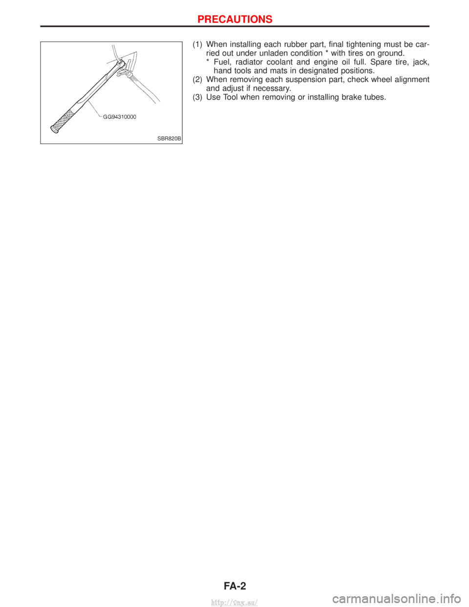
(1) When installing each rubber part, final tightening must be car-ried out under unladen condition * with tires on ground.
* Fuel, radiator coolant and engine oil full. Spare tire, jack,hand tools and mats in designated positions.
(2) When removing each suspension part, check wheel alignment and adjust if necessary.
(3) Use Tool when removing or installing brake tubes.
SBR820B
PRECAUTIONS
FA-2
http://vnx.su/
Page 1119 of 1833
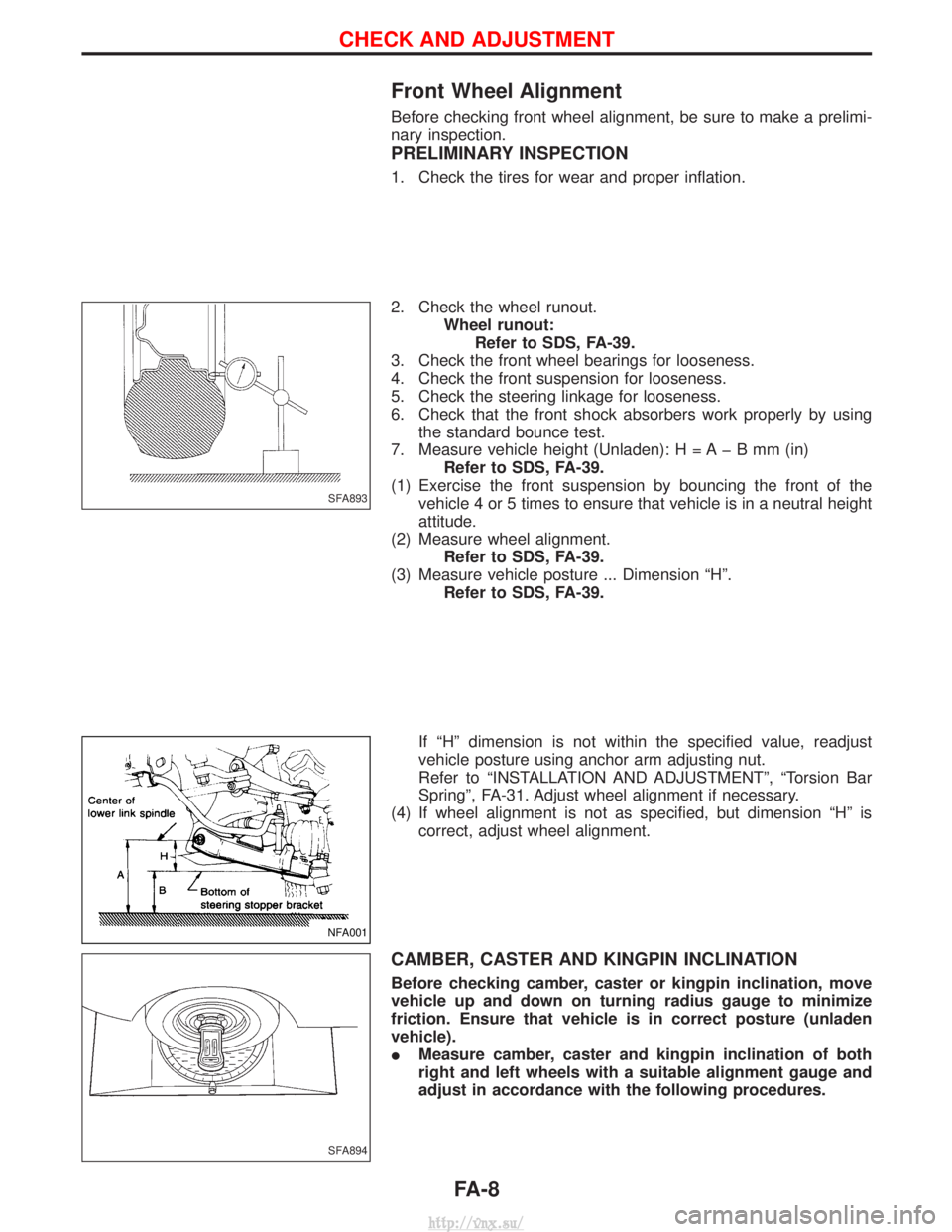
Front Wheel Alignment
Before checking front wheel alignment, be sure to make a prelimi-
nary inspection.
PRELIMINARY INSPECTION
1. Check the tires for wear and proper inflation.
2. Check the wheel runout.Wheel runout:Refer to SDS, FA-39.
3. Check the front wheel bearings for looseness.
4. Check the front suspension for looseness.
5. Check the steering linkage for looseness.
6. Check that the front shock absorbers work properly by using the standard bounce test.
7. Measure vehicle height (Unladen): H = A þ B mm (in) Refer to SDS, FA-39.
(1) Exercise the front suspension by bouncing the front of the vehicle 4 or 5 times to ensure that vehicle is in a neutral height
attitude.
(2) Measure wheel alignment. Refer to SDS, FA-39.
(3) Measure vehicle posture ... Dimension ªHº. Refer to SDS, FA-39.
If ªHº dimension is not within the specified value, readjust
vehicle posture using anchor arm adjusting nut.
Refer to ªINSTALLATION AND ADJUSTMENTº, ªTorsion Bar
Springº, FA-31. Adjust wheel alignment if necessary.
(4) If wheel alignment is not as specified, but dimension ªHº is correct, adjust wheel alignment.
CAMBER, CASTER AND KINGPIN INCLINATION
Before checking camber, caster or kingpin inclination, move
vehicle up and down on turning radius gauge to minimize
friction. Ensure that vehicle is in correct posture (unladen
vehicle).
IMeasure camber, caster and kingpin inclination of both
right and left wheels with a suitable alignment gauge and
adjust in accordance with the following procedures.
SFA893
NFA001
SFA894
CHECK AND ADJUSTMENT
FA-8
http://vnx.su/
Page 1120 of 1833
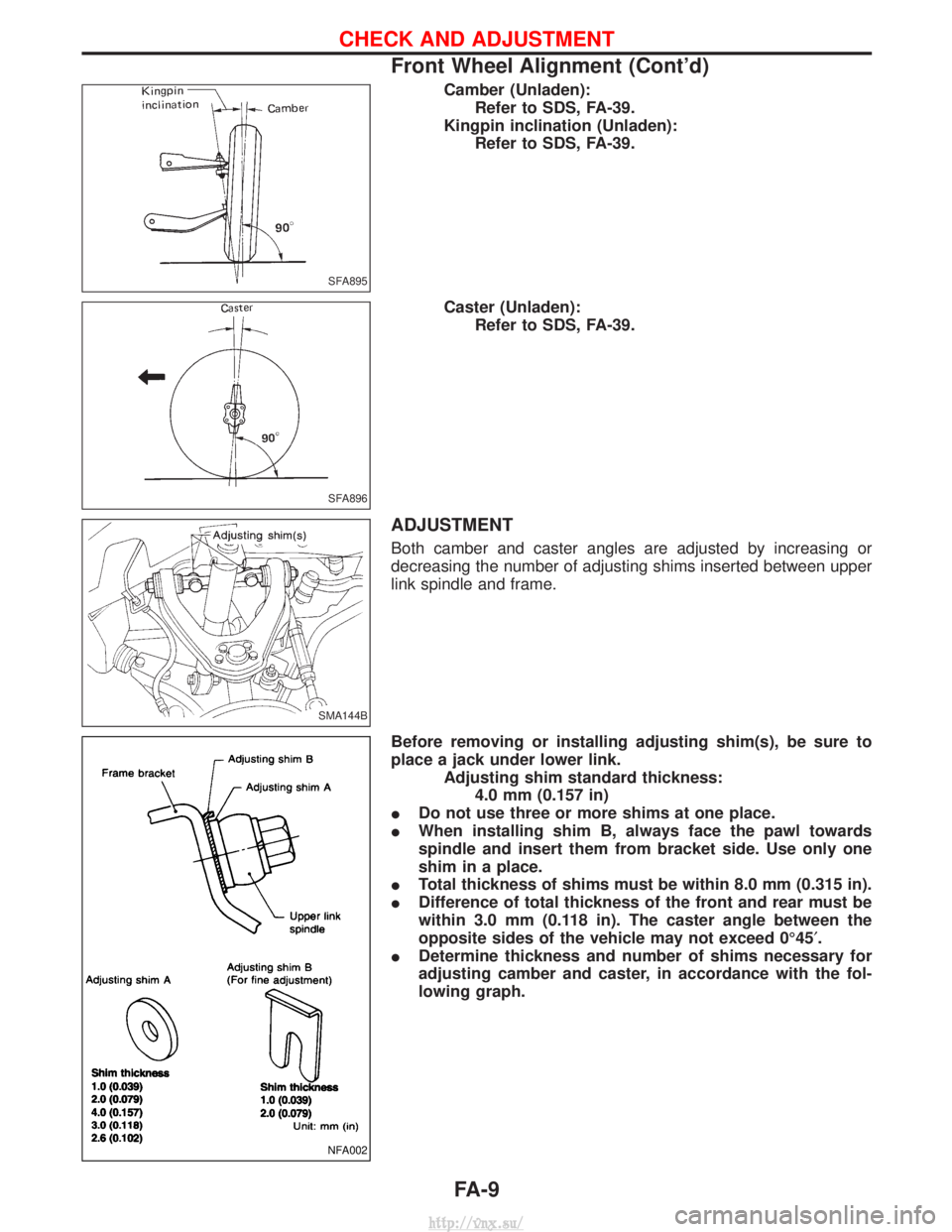
Camber (Unladen):Refer to SDS, FA-39.
Kingpin inclination (Unladen): Refer to SDS, FA-39.
Caster (Unladen): Refer to SDS, FA-39.
ADJUSTMENT
Both camber and caster angles are adjusted by increasing or
decreasing the number of adjusting shims inserted between upper
link spindle and frame.
Before removing or installing adjusting shim(s), be sure to
place a jack under lower link. Adjusting shim standard thickness:4.0 mm (0.157 in)
I Do not use three or more shims at one place.
I When installing shim B, always face the pawl towards
spindle and insert them from bracket side. Use only one
shim in a place.
I Total thickness of shims must be within 8.0 mm (0.315 in).
I Difference of total thickness of the front and rear must be
within 3.0 mm (0.118 in). The caster angle between the
opposite sides of the vehicle may not exceed 0É45 ¢.
I Determine thickness and number of shims necessary for
adjusting camber and caster, in accordance with the fol-
lowing graph.
SFA895
SFA896
SMA144B
NFA002
CHECK AND ADJUSTMENT
Front Wheel Alignment (Cont'd)
FA-9
http://vnx.su/
Page 1121 of 1833
![NISSAN TERRANO 2004 Service Repair Manual [Example]
(Measures taken at one side):
(1)
Angle
Specified value Measured Change
Camber angle 0É30¢ 0É5¢+0É25¢
Caster angle 1É54¢ 2É10¢þ0É16¢
The above values relate to the graph below:
NISSAN TERRANO 2004 Service Repair Manual [Example]
(Measures taken at one side):
(1)
Angle
Specified value Measured Change
Camber angle 0É30¢ 0É5¢+0É25¢
Caster angle 1É54¢ 2É10¢þ0É16¢
The above values relate to the graph below:](/manual-img/5/57394/w960_57394-1120.png)
[Example]
(Measures taken at one side):
(1)
Angle
Specified value Measured Change
Camber angle 0É30¢ 0É5¢+0É25¢
Caster angle 1É54¢ 2É10¢þ0É16¢
The above values relate to the graph below:
Shim thickness selection graph
(2) Obtain intersection point of lines in accordance with the graph.
Front: 1.4 mm
Rear: 2.0 mm
(3) Choose shims which are nearest to the values found in the graph:Front: 1.6 mm
Rear: 2.0 mm
(4) If shim thicknesses as calculated appear not to be available, combinations of different shims should be used to meet the
desired total thickness of the shims.
EFA015
CHECK AND ADJUSTMENT
Front Wheel Alignment (Cont'd)
FA-10
http://vnx.su/