2004 NISSAN TERRANO Door sensor
[x] Cancel search: Door sensorPage 1180 of 1833
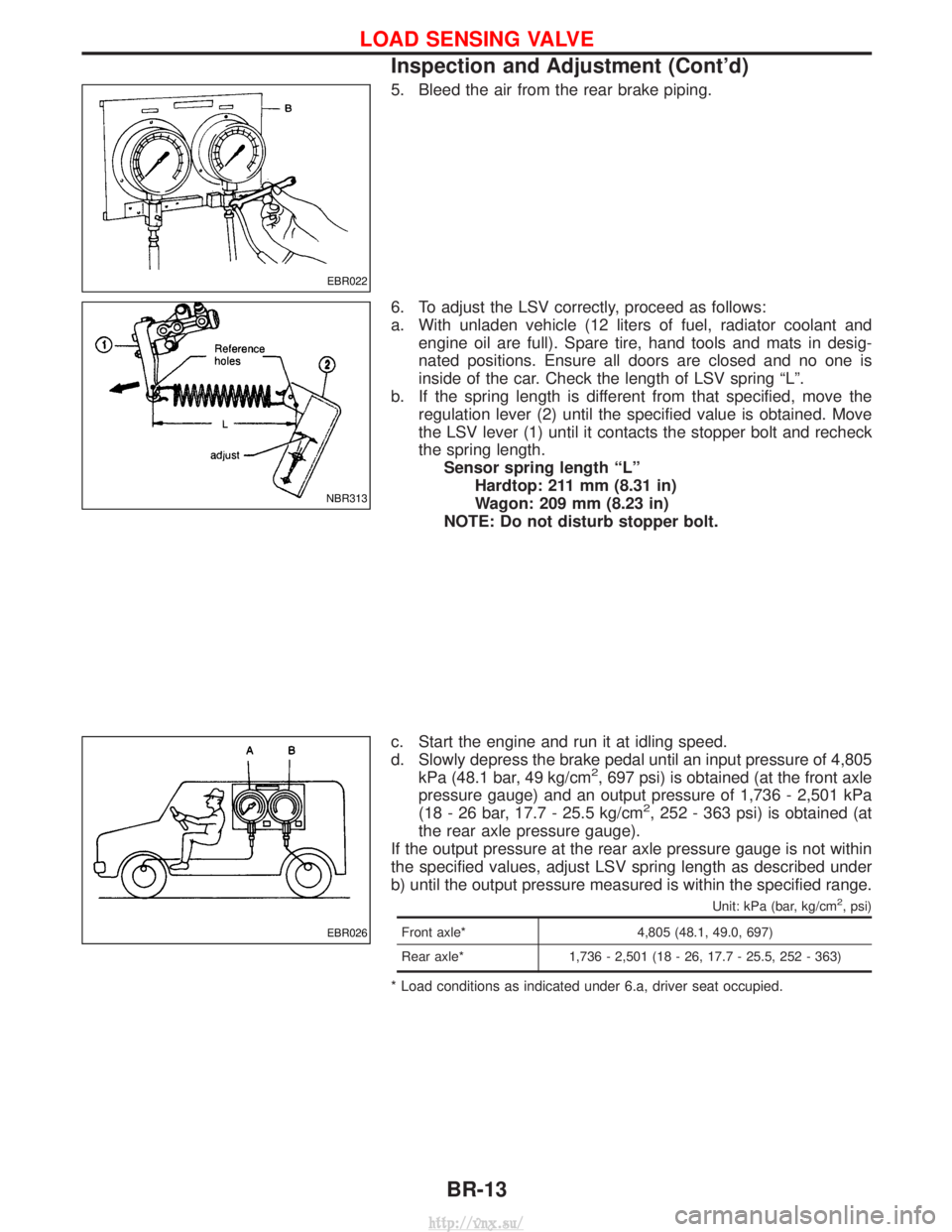
5. Bleed the air from the rear brake piping.
6. To adjust the LSV correctly, proceed as follows:
a. With unladen vehicle (12 liters of fuel, radiator coolant andengine oil are full). Spare tire, hand tools and mats in desig-
nated positions. Ensure all doors are closed and no one is
inside of the car. Check the length of LSV spring ªLº.
b. If the spring length is different from that specified, move the regulation lever (2) until the specified value is obtained. Move
the LSV lever (1) until it contacts the stopper bolt and recheck
the spring length.Sensor spring length ªLº Hardtop: 211 mm (8.31 in)
Wagon: 209 mm (8.23 in)
NOTE: Do not disturb stopper bolt.
c. Start the engine and run it at idling speed.
d. Slowly depress the brake pedal until an input pressure of 4,805 kPa (48.1 bar, 49 kg/cm
2, 697 psi) is obtained (at the front axle
pressure gauge) and an output pressure of 1,736 - 2,501 kPa
(18 - 26 bar, 17.7 - 25.5 kg/cm
2, 252 - 363 psi) is obtained (at
the rear axle pressure gauge).
If the output pressure at the rear axle pressure gauge is not within
the specified values, adjust LSV spring length as described under
b) until the output pressure measured is within the specified range.
Unit: kPa (bar, kg/cm2, psi)
Front axle* 4,805 (48.1, 49.0, 697)
Rear axle* 1,736 - 2,501 (18 - 26, 17.7 - 25.5, 252 - 363)
* Load conditions as indicated under 6.a, driver seat occupied.
EBR022
NBR313
EBR026
LOAD SENSING VALVE
Inspection and Adjustment (Cont'd)
BR-13
http://vnx.su/
Page 1328 of 1833
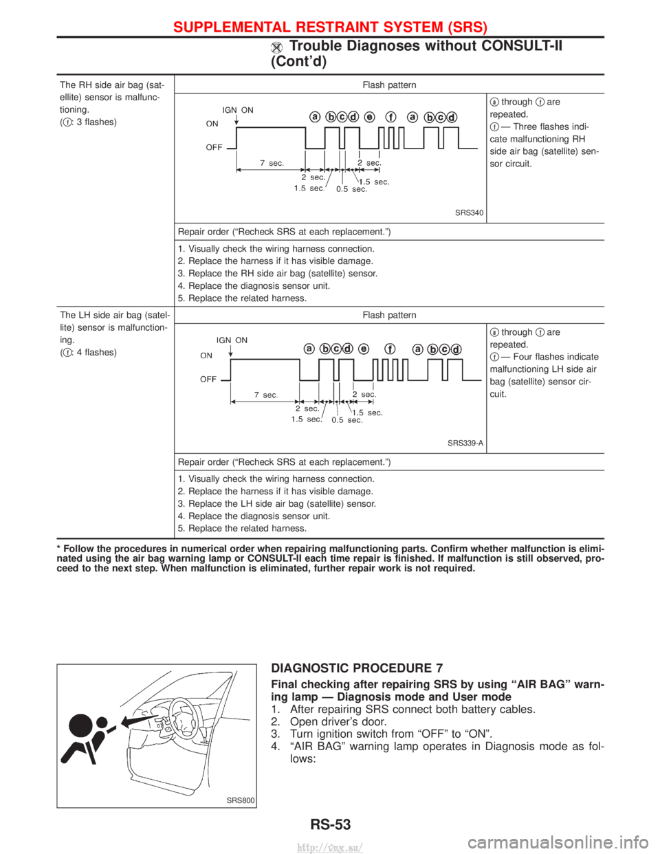
The RH side air bag (sat-
ellite) sensor is malfunc-
tioning.
(q
f: 3 flashes) Flash pattern
SRS340
qathrough
qfare
repeated.
q
fÐ Three flashes indi-
cate malfunctioning RH
side air bag (satellite) sen-
sor circuit.
Repair order (ªRecheck SRS at each replacement.º)
1. Visually check the wiring harness connection.
2. Replace the harness if it has visible damage.
3. Replace the RH side air bag (satellite) sensor.
4. Replace the diagnosis sensor unit.
5. Replace the related harness.
The LH side air bag (satel-
lite) sensor is malfunction-
ing.
( q
f: 4 flashes) Flash pattern
SRS339-A
qathrough
qfare
repeated.
q
fÐ Four flashes indicate
malfunctioning LH side air
bag (satellite) sensor cir-
cuit.
Repair order (ªRecheck SRS at each replacement.º)
1. Visually check the wiring harness connection.
2. Replace the harness if it has visible damage.
3. Replace the LH side air bag (satellite) sensor.
4. Replace the diagnosis sensor unit.
5. Replace the related harness.
* Follow the procedures in numerical order when repairing malfunctioning parts. Confirm whether malfunction is elimi-
nated using the air bag warning lamp or CONSULT-II each time repair is finished. If malfunction is still observed, pro-
ceed to the next step. When malfunction is eliminated, further repair work is not required.
DIAGNOSTIC PROCEDURE 7
Final checking after repairing SRS by using ªAIR BAGº warn-
ing lamp Ð Diagnosis mode and User mode
1. After repairing SRS connect both battery cables.
2. Open driver's door.
3. Turn ignition switch from ªOFFº to ªONº.
4. ªAIR BAGº warning lamp operates in Diagnosis mode as fol- lows:
SRS800
SUPPLEMENTAL RESTRAINT SYSTEM (SRS)
Trouble Diagnoses without CONSULT-II
(Cont'd)
RS-53
http://vnx.su/
Page 1517 of 1833
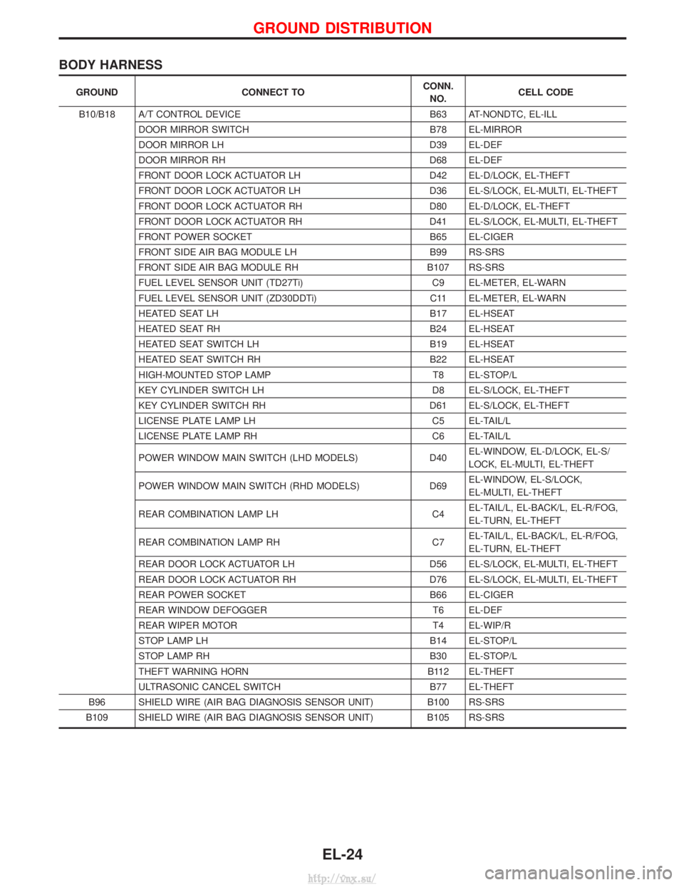
BODY HARNESS
GROUNDCONNECT TO CONN.
NO. CELL CODE
B10/B18 A/T CONTROL DEVICE B63 AT-NONDTC, EL-ILL
DOOR MIRROR SWITCH B78 EL-MIRROR
DOOR MIRROR LH D39 EL-DEF
DOOR MIRROR RH D68 EL-DEF
FRONT DOOR LOCK ACTUATOR LH D42 EL-D/LOCK, EL-THEFT
FRONT DOOR LOCK ACTUATOR LH D36 EL-S/LOCK, EL-MULTI, EL-THEFT
FRONT DOOR LOCK ACTUATOR RH D80 EL-D/LOCK, EL-THEFT
FRONT DOOR LOCK ACTUATOR RH D41 EL-S/LOCK, EL-MULTI, EL-THEFT
FRONT POWER SOCKET B65 EL-CIGER
FRONT SIDE AIR BAG MODULE LH B99 RS-SRS
FRONT SIDE AIR BAG MODULE RH B107 RS-SRS
FUEL LEVEL SENSOR UNIT (TD27Ti) C9 EL-METER, EL-WARN
FUEL LEVEL SENSOR UNIT (ZD30DDTi) C11 EL-METER, EL-WARN
HEATED SEAT LH B17 EL-HSEAT
HEATED SEAT RH B24 EL-HSEAT
HEATED SEAT SWITCH LH B19 EL-HSEAT
HEATED SEAT SWITCH RH B22 EL-HSEAT
HIGH-MOUNTED STOP LAMP T8 EL-STOP/L
KEY CYLINDER SWITCH LH D8 EL-S/LOCK, EL-THEFT
KEY CYLINDER SWITCH RH D61 EL-S/LOCK, EL-THEFT
LICENSE PLATE LAMP LH C5 EL-TAIL/L
LICENSE PLATE LAMP RH C6 EL-TAIL/L
POWER WINDOW MAIN SWITCH (LHD MODELS) D40EL-WINDOW, EL-D/LOCK, EL-S/
LOCK, EL-MULTI, EL-THEFT
POWER WINDOW MAIN SWITCH (RHD MODELS) D69EL-WINDOW, EL-S/LOCK,
EL-MULTI, EL-THEFT
REAR COMBINATION LAMP LH C4EL-TAIL/L, EL-BACK/L, EL-R/FOG,
EL-TURN, EL-THEFT
REAR COMBINATION LAMP RH C7EL-TAIL/L, EL-BACK/L, EL-R/FOG,
EL-TURN, EL-THEFT
REAR DOOR LOCK ACTUATOR LH D56 EL-S/LOCK, EL-MULTI, EL-THEFT
REAR DOOR LOCK ACTUATOR RH D76 EL-S/LOCK, EL-MULTI, EL-THEFT
REAR POWER SOCKET B66 EL-CIGER
REAR WINDOW DEFOGGER T6 EL-DEF
REAR WIPER MOTOR T4 EL-WIP/R
STOP LAMP LH B14 EL-STOP/L
STOP LAMP RH B30 EL-STOP/L
THEFT WARNING HORN B112 EL-THEFT
ULTRASONIC CANCEL SWITCH B77 EL-THEFT
B96 SHIELD WIRE (AIR BAG DIAGNOSIS SENSOR UNIT) B100 RS-SRS
B109 SHIELD WIRE (AIR BAG DIAGNOSIS SENSOR UNIT) B105 RS-SRS
GROUND DISTRIBUTION
EL-24
http://vnx.su/
Page 1656 of 1833
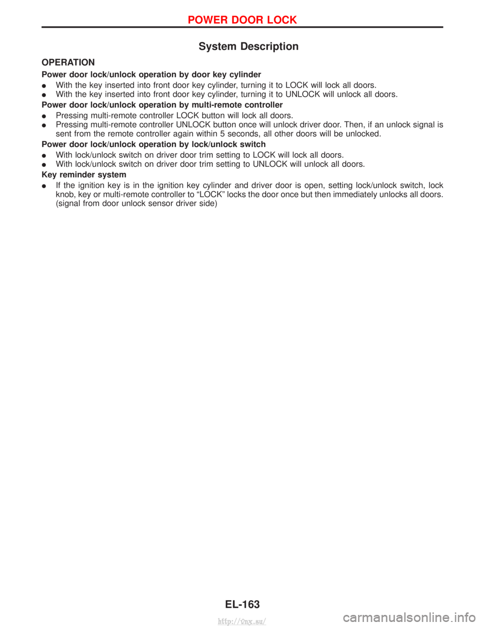
System Description
OPERATION
Power door lock/unlock operation by door key cylinder
IWith the key inserted into front door key cylinder, turning it to LOCK will lock all doors.
I With the key inserted into front door key cylinder, turning it to UNLOCK will unlock all doors.
Power door lock/unlock operation by multi-remote controller
I Pressing multi-remote controller LOCK button will lock all doors.
I Pressing multi-remote controller UNLOCK button once will unlock driver door. Then, if an unlock signal is
sent from the remote controller again within 5 seconds, all other doors will be unlocked.
Power door lock/unlock operation by lock/unlock switch
I With lock/unlock switch on driver door trim setting to LOCK will lock all doors.
I With lock/unlock switch on driver door trim setting to UNLOCK will unlock all doors.
Key reminder system
I If the ignition key is in the ignition key cylinder and driver door is open, setting lock/unlock switch, lock
knob, key or multi-remote controller to ªLOCKº locks the door once but then immediately unlocks all doors.
(signal from door unlock sensor driver side)
POWER DOOR LOCK
EL-163
http://vnx.su/
Page 1665 of 1833
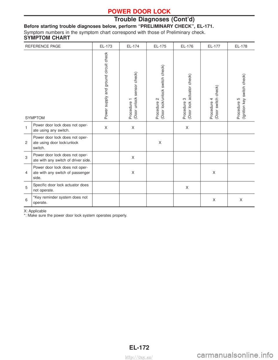
Before starting trouble diagnoses below, perform ªPRELIMINARY CHECKº, EL-171.
Symptom numbers in the symptom chart correspond with those of Preliminary check.
SYMPTOM CHART
REFERENCE PAGEEL-173 EL-174 EL-175 EL-176 EL-177 EL-178
SYMPTOM
Power supply and ground circuit check
Procedure 1
(Door unlock sensor check)
Procedure 2
(Door lock/unlock switch check)
Procedure 3
(Door lock actuator check)
Procedure 4
(Door switch check)
Procedure 5
(Ignition key switch check)
1 Power door lock does not oper-
ate using any switch. XX X
2 Power door lock does not oper-
ate using door lock/unlock
switch. X
3 Power door lock does not oper-
ate with any switch of driver side. X
4 Power door lock does not oper-
ate with any switch of passenger
side. XX
5 Specific door lock actuator does
not operate. X
6 *Key reminder system does not
operate. XX
X: Applicable
*: Make sure the power door lock system operates properly.
POWER DOOR LOCK
Trouble Diagnoses (Cont'd)
EL-172
http://vnx.su/
Page 1667 of 1833
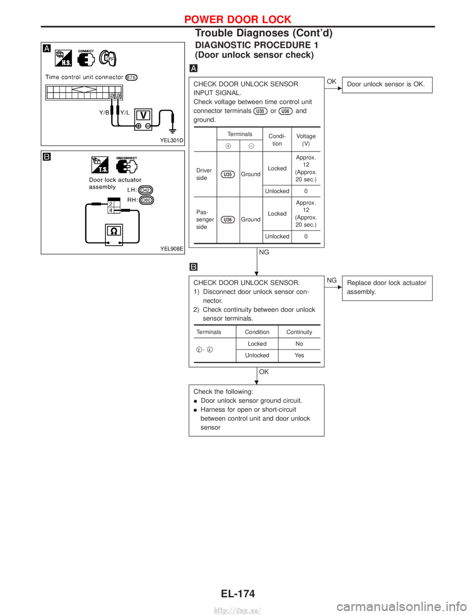
DIAGNOSTIC PROCEDURE 1
(Door unlock sensor check)
CHECK DOOR UNLOCK SENSOR
INPUT SIGNAL.
Check voltage between time control unit
connector terminals
U35orU36and
ground.
NG
EOK Door unlock sensor is OK.
CHECK DOOR UNLOCK SENSOR.
1) Disconnect door unlock sensor con-
nector.
2) Check continuity between door unlock sensor terminals.
OK
ENG Replace door lock actuator
assembly.
Check the following:
IDoor unlock sensor ground circuit.
I Harness for open or short-circuit
between control unit and door unlock
sensor
Terminals
Condi-
tion Voltage
(V)
!@
Driver
side
U35Ground Locked Approx.
12
(Approx. 20 sec.)
Unlocked 0
Pas-
senger
side
U36Ground Locked Approx.
12
(Approx. 20 sec.)
Unlocked 0
Terminals Condition Continuity
q
2- q4Locked
No
Unlocked Yes
YEL301D
YEL908E
H
H
POWER DOOR LOCK
Trouble Diagnoses (Cont'd)
EL-174
http://vnx.su/
Page 1686 of 1833
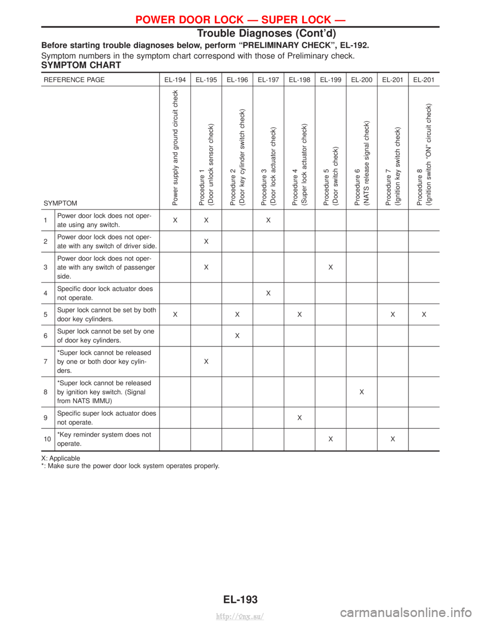
Before starting trouble diagnoses below, perform ªPRELIMINARY CHECKº, EL-192.
Symptom numbers in the symptom chart correspond with those of Preliminary check.
SYMPTOM CHART
REFERENCE PAGEEL-194 EL-195 EL-196 EL-197 EL-198 EL-199 EL-200 EL-201 EL-201
SYMPTOM
Power supply and ground circuit check
Procedure 1
(Door unlock sensor check)
Procedure 2
(Door key cylinder switch check)
Procedure 3
(Door lock actuator check)
Procedure 4
(Super lock actuator check)
Procedure 5
(Door switch check)
Procedure 6
(NATS release signal check)
Procedure 7
(Ignition key switch check)
Procedure 8
(Ignition switch ªONº circuit check)
1 Power door lock does not oper-
ate using any switch. XX X
2 Power door lock does not oper-
ate with any switch of driver side. X
3 Power door lock does not oper-
ate with any switch of passenger
side. XX
4 Specific door lock actuator does
not operate. X
5 Super lock cannot be set by both
door key cylinders. XXX XX
6 Super lock cannot be set by one
of door key cylinders. X
7 *Super lock cannot be released
by one or both door key cylin-
ders. X
8 *Super lock cannot be released
by ignition key switch. (Signal
from NATS IMMU) X
9 Specific super lock actuator does
not operate. X
10 *Key reminder system does not
operate. XX
X: Applicable
*: Make sure the power door lock system operates properly.
POWER DOOR LOCK Ð SUPER LOCK Ð
Trouble Diagnoses (Cont'd)
EL-193
http://vnx.su/
Page 1688 of 1833
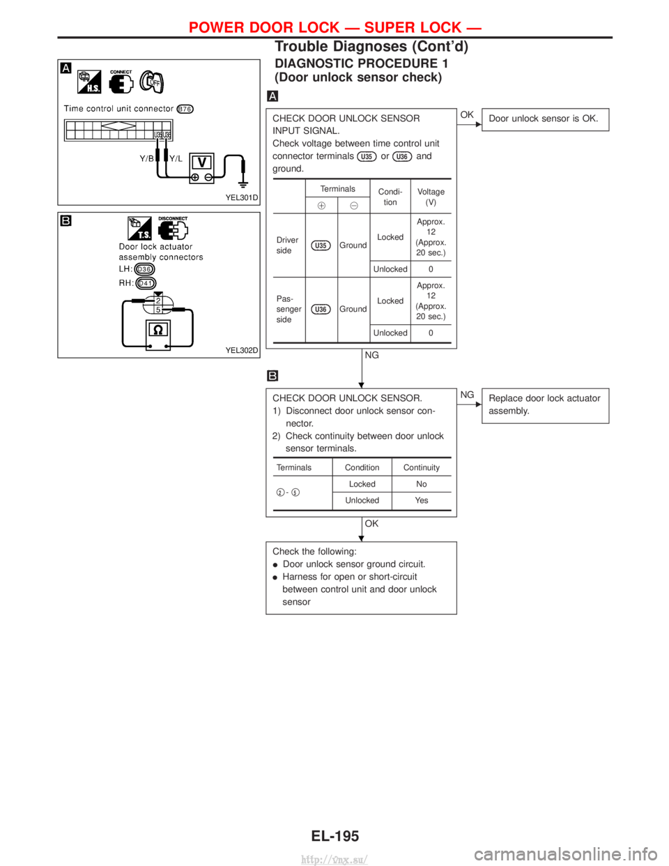
DIAGNOSTIC PROCEDURE 1
(Door unlock sensor check)
CHECK DOOR UNLOCK SENSOR
INPUT SIGNAL.
Check voltage between time control unit
connector terminals
U35orU36and
ground.
NG
EOK Door unlock sensor is OK.
CHECK DOOR UNLOCK SENSOR.
1) Disconnect door unlock sensor con-
nector.
2) Check continuity between door unlock sensor terminals.
OK
ENG Replace door lock actuator
assembly.
Check the following:
IDoor unlock sensor ground circuit.
I Harness for open or short-circuit
between control unit and door unlock
sensor
Terminals
Condi-
tion Voltage
(V)
!@
Driver
side
U35Ground Locked Approx.
12
(Approx. 20 sec.)
Unlocked 0
Pas-
senger
side
U36Ground Locked Approx.
12
(Approx. 20 sec.)
Unlocked 0
Terminals Condition Continuity
q
2- q5Locked
No
Unlocked Yes
YEL301D
YEL302D
H
H
POWER DOOR LOCK Ð SUPER LOCK Ð
Trouble Diagnoses (Cont'd)
EL-195
http://vnx.su/