2004 NISSAN PATROL transm
[x] Cancel search: transmPage 1 of 579
Edition: July 2004
Release: July 2004 (01)
Publication No.: SM4E00-1Y61E0E
Reference No.: 7711347233GENERAL INFORMATIONGI
MAINTENANCEMA
ENGINE MECHANICALEM
ENGINE LUBRICATION &
COOLING SYSTEMSLC
ENGINE CONTROL SYSTEMEC
ACCELERATOR CONTROL,
FUEL & EXHAUST SYSTEMFE
CLUTCHCL
MANUAL TRANSMISSIONMT
AUTOMATIC TRANSMISSIONAT
TRANSFERTF
PROPELLER SHAFT &
DIFFERENTIAL CARRIERPD
FRONT AXLE & FRONT SUSPENSIONFA
REAR AXLE & REAR SUSPENSIONRA
BRAKE SYSTEMBR
STEERING SYSTEMST
RESTRAINT SYSTEMRS
BODY & TRIMBT
HEATER & AIR CONDITIONERHA
ELECTRICAL SYSTEMEL
ALPHABETICAL INDEXIDX
PATROL
MODEL Y61 SERIES
NISSAN EUROPE S.A.S.
2004 NISSAN EUROPE S.A.S.
Produced in The Netherlands
Not to be reproduced in whole or in part
without the prior written permission of
Nissan Europe S.A.S., Paris, France.
QUICK REFERENCE INDEX
Page 3 of 579
SECTION
AT
MODIFICATION NOTICE:
+Wiring diagrams have been changed.
+ Service data and Speci®cations (SDS) have been changed.
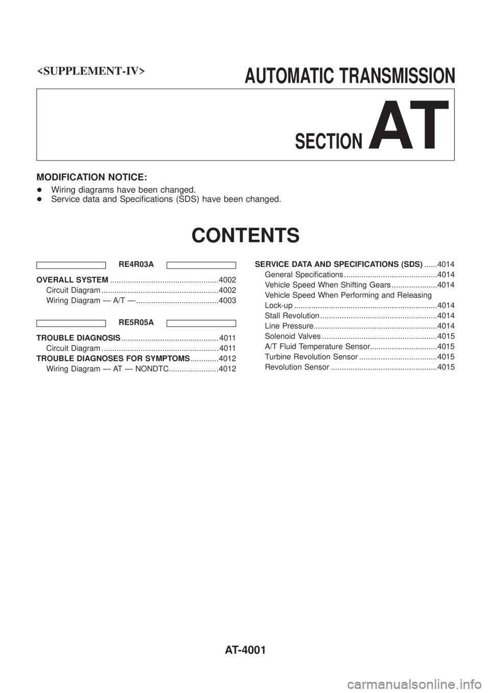
CONTENTS
RE4R03A
OVERALL SYSTEM ..................................................4002
Circuit Diagram ......................................................4002
Wiring Diagram Ð A/T Ð ......................................4003
RE5R05A
TROUBLE DIAGNOSIS ............................................. 4011
Circuit Diagram ...................................................... 4011
TROUBLE DIAGNOSES FOR SYMPTOMS .............4012
Wiring Diagram Ð AT Ð NONDTC.......................4012 SERVICE DATA AND SPECIFICATIONS (SDS)
......4014
General Speci®cations ...........................................4014
Vehicle Speed When Shifting Gears .....................4014
Vehicle Speed When Performing and Releasing
Lock-up ..................................................................4014
Stall Revolution ......................................................4014
Line Pressure.........................................................4014
Solenoid Valves .....................................................4015
A/T Fluid Temperature Sensor...............................4015
Turbine Revolution Sensor ....................................4015
Revolution Sensor .................................................4015
AT-4001
Page 16 of 579
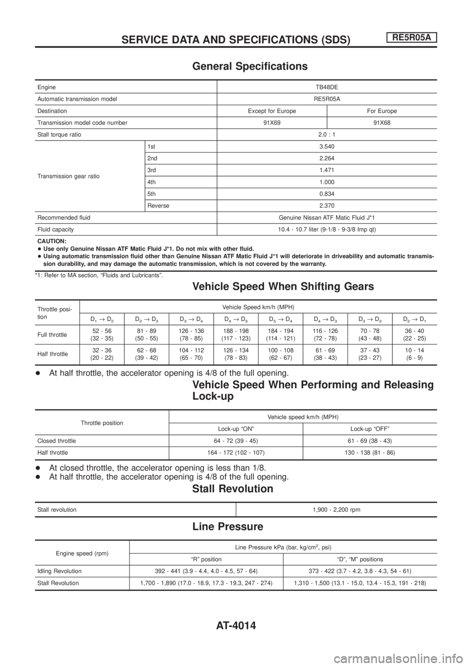
General Speci®cations
EngineTB48DE
Automatic transmission modelRE5R05A
Destination Except for Europe For Europe
Transmission model code number 91X69 91X68
Stall torque ratio2.0:1
Transmission gear ratio1st 3.540
2nd 2.264
3rd 1.471
4th 1.000
5th 0.834
Reverse 2.370
Recommended ¯uid Genuine Nissan ATF Matic Fluid J*1
Fluid capacity10.4 - 10.7 liter (9-1/8 - 9-3/8 Imp qt)
CAUTION:
+Use only Genuine Nissan ATF Matic Fluid J*1. Do not mix with other ¯uid.
+Using automatic transmission ¯uid other than Genuine Nissan ATF Matic Fluid J*1 will deteriorate in driveability and automatic transmis-
sion durability, and may damage the automatic transmission, which is not covered by the warranty.
*1: Refer to MA section, ªFluids and Lubricantsº.
Vehicle Speed When Shifting Gears
Throttle posi-
tionVehicle Speed km/h (MPH)
D
1®D2D2®D3D3®D4D4®D5D5®D4D4®D3D3®D2D2®D1
Full throttle52-56
(32 - 35)81-89
(50 - 55)126 - 136
(78 - 85)188 - 198
(117 - 123)184 - 194
(114 - 121)116 - 126
(72 - 78)70-78
(43 - 48)36-40
(22 - 25)
Half throttle32-36
(20 - 22)62-68
(39 - 42)104 - 112
(65 - 70)126 - 134
(78 - 83)100 - 108
(62 - 67)61-69
(38 - 43)37-43
(23 - 27)10-14
(6-9)
+At half throttle, the accelerator opening is 4/8 of the full opening.
Vehicle Speed When Performing and Releasing
Lock-up
Throttle positionVehicle speed km/h (MPH)
Lock-up ªONº Lock-up ªOFFº
Closed throttle 64 - 72 (39 - 45) 61 - 69 (38 - 43)
Half throttle 164 - 172 (102 - 107) 130 - 138 (81 - 86)
+At closed throttle, the accelerator opening is less than 1/8.
+At half throttle, the accelerator opening is 4/8 of the full opening.
Stall Revolution
Stall revolution1,900 - 2,200 rpm
Line Pressure
Engine speed (rpm)Line Pressure kPa (bar, kg/cm
2, psi)
ªRº position ªDº, ªMº positions
Idling Revolution 392 - 441 (3.9 - 4.4, 4.0 - 4.5, 57 - 64) 373 - 422 (3.7 - 4.2, 3.8 - 4.3, 54 - 61)
Stall Revolution 1,700 - 1,890 (17.0 - 18.9, 17.3 - 19.3, 247 - 274) 1,310 - 1,500 (13.1 - 15.0, 13.4 - 15.3, 191 - 218)
SERVICE DATA AND SPECIFICATIONS (SDS)RE5R05A
AT-4014
Page 86 of 579
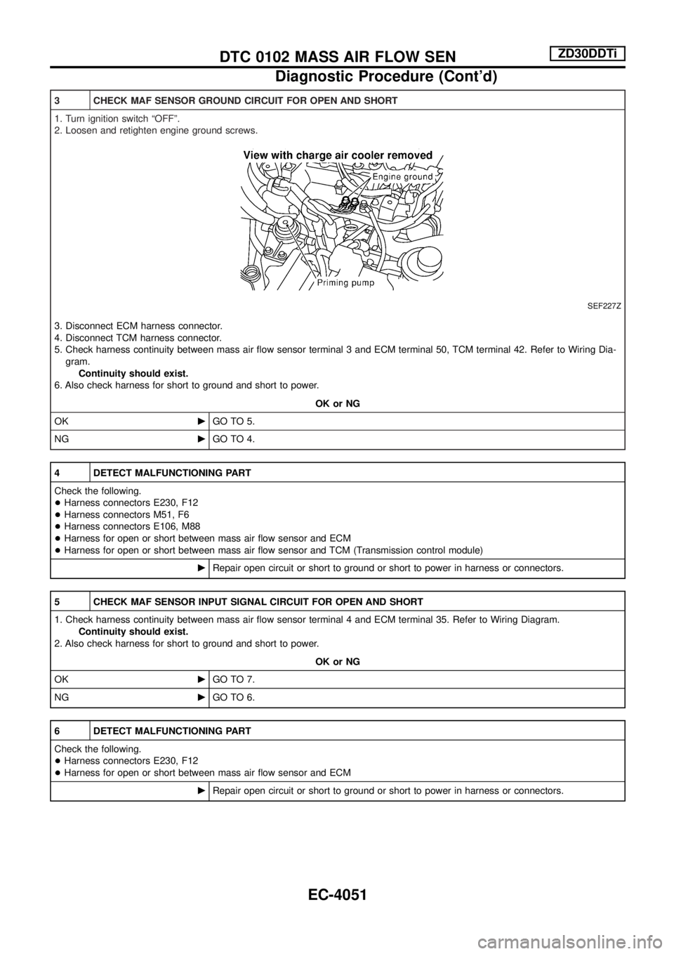
3 CHECK MAF SENSOR GROUND CIRCUIT FOR OPEN AND SHORT
1. Turn ignition switch ªOFFº.
2. Loosen and retighten engine ground screws.
SEF227Z
3. Disconnect ECM harness connector.
4. Disconnect TCM harness connector.
5. Check harness continuity between mass air ¯ow sensor terminal 3 and ECM terminal 50, TCM terminal 42. Refer to Wiring Dia-
gram.
Continuity should exist.
6. Also check harness for short to ground and short to power.
OK or NG
OKcGO TO 5.
NGcGO TO 4.
4 DETECT MALFUNCTIONING PART
Check the following.
+Harness connectors E230, F12
+Harness connectors M51, F6
+Harness connectors E106, M88
+Harness for open or short between mass air ¯ow sensor and ECM
+Harness for open or short between mass air ¯ow sensor and TCM (Transmission control module)
cRepair open circuit or short to ground or short to power in harness or connectors.
5 CHECK MAF SENSOR INPUT SIGNAL CIRCUIT FOR OPEN AND SHORT
1. Check harness continuity between mass air ¯ow sensor terminal 4 and ECM terminal 35. Refer to Wiring Diagram.
Continuity should exist.
2. Also check harness for short to ground and short to power.
OK or NG
OKcGO TO 7.
NGcGO TO 6.
6 DETECT MALFUNCTIONING PART
Check the following.
+Harness connectors E230, F12
+Harness for open or short between mass air ¯ow sensor and ECM
cRepair open circuit or short to ground or short to power in harness or connectors.
DTC 0102 MASS AIR FLOW SENZD30DDTi
Diagnostic Procedure (Cont'd)
EC-4051
Page 291 of 579
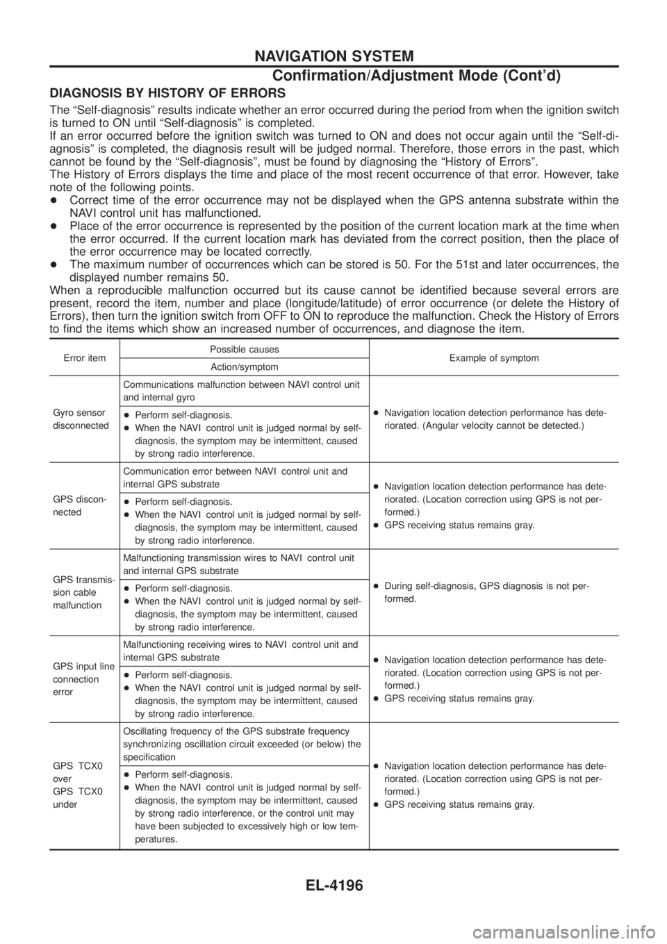
DIAGNOSIS BY HISTORY OF ERRORS
The ªSelf-diagnosisº results indicate whether an error occurred during the period from when the ignition switch
is turned to ON until ªSelf-diagnosisº is completed.
If an error occurred before the ignition switch was turned to ON and does not occur again until the ªSelf-di-
agnosisº is completed, the diagnosis result will be judged normal. Therefore, those errors in the past, which
cannot be found by the ªSelf-diagnosisº, must be found by diagnosing the ªHistory of Errorsº.
The History of Errors displays the time and place of the most recent occurrence of that error. However, take
note of the following points.
+Correct time of the error occurrence may not be displayed when the GPS antenna substrate within the
NAVI control unit has malfunctioned.
+ Place of the error occurrence is represented by the position of the current location mark at the time when
the error occurred. If the current location mark has deviated from the correct position, then the place of
the error occurrence may be located correctly.
+ The maximum number of occurrences which can be stored is 50. For the 51st and later occurrences, the
displayed number remains 50.
When a reproducible malfunction occurred but its cause cannot be identi®ed because several errors are
present, record the item, number and place (longitude/latitude) of error occurrence (or delete the History of
Errors), then turn the ignition switch from OFF to ON to reproduce the malfunction. Check the History of Errors
to ®nd the items which show an increased number of occurrences, and diagnose the item.
Error item Possible causes
Example of symptom
Action/symptom
Gyro sensor
disconnected Communications malfunction between NAVI control unit
and internal gyro
+Navigation location detection performance has dete-
riorated. (Angular velocity cannot be detected.)
+
Perform self-diagnosis.
+ When the NAVI control unit is judged normal by self-
diagnosis, the symptom may be intermittent, caused
by strong radio interference.
GPS discon-
nected Communication error between NAVI control unit and
internal GPS substrate
+Navigation location detection performance has dete-
riorated. (Location correction using GPS is not per-
formed.)
+ GPS receiving status remains gray.
+
Perform self-diagnosis.
+ When the NAVI control unit is judged normal by self-
diagnosis, the symptom may be intermittent, caused
by strong radio interference.
GPS transmis-
sion cable
malfunction Malfunctioning transmission wires to NAVI control unit
and internal GPS substrate
+During self-diagnosis, GPS diagnosis is not per-
formed.
+
Perform self-diagnosis.
+ When the NAVI control unit is judged normal by self-
diagnosis, the symptom may be intermittent, caused
by strong radio interference.
GPS input line
connection
error Malfunctioning receiving wires to NAVI control unit and
internal GPS substrate
+Navigation location detection performance has dete-
riorated. (Location correction using GPS is not per-
formed.)
+ GPS receiving status remains gray.
+
Perform self-diagnosis.
+ When the NAVI control unit is judged normal by self-
diagnosis, the symptom may be intermittent, caused
by strong radio interference.
GPS TCX0
over
GPS TCX0
under Oscillating frequency of the GPS substrate frequency
synchronizing oscillation circuit exceeded (or below) the
speci®cation
+Navigation location detection performance has dete-
riorated. (Location correction using GPS is not per-
formed.)
+ GPS receiving status remains gray.
+
Perform self-diagnosis.
+ When the NAVI control unit is judged normal by self-
diagnosis, the symptom may be intermittent, caused
by strong radio interference, or the control unit may
have been subjected to excessively high or low tem-
peratures.
NAVIGATION SYSTEM
Con®rmation/Adjustment Mode (Cont'd)
EL-4196
Page 471 of 579
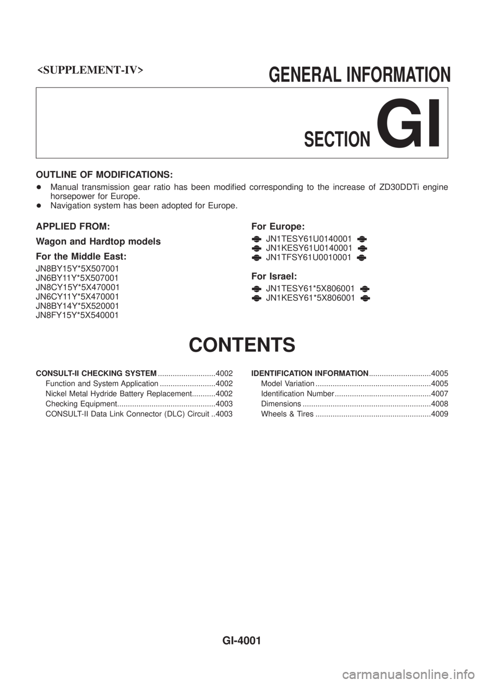
GI
OUTLINE OF MODIFICATIONS:
+Manual transmission gear ratio has been modi®ed corresponding to the increase of ZD30DDTi engine
horsepower for Europe.
+ Navigation system has been adopted for Europe.
APPLIED FROM:
Wagon and Hardtop models
For the Middle East:
JN8BY15Y*5X507001
JN6BY11Y*5X507001
JN8CY15Y*5X470001
JN6CY11Y*5X470001
JN8BY14Y*5X520001
JN8FY15Y*5X540001
For Europe:
JN1TESY61U0140001
JN1KESY61U0140001
JN1TFSY61U0010001
For Israel:
JN1TESY61*5X806001
JN1KESY61*5X806001
CONTENTS
CONSULT-II CHECKING SYSTEM ...........................4002
Function and System Application ..........................4002
Nickel Metal Hydride Battery Replacement...........4002
Checking Equipment..............................................4003
CONSULT-II Data Link Connector (DLC) Circuit ..4003 IDENTIFICATION INFORMATION
.............................4005
Model Variation ......................................................4005
Identi®cation Number .............................................4007
Dimensions ............................................................4008
Wheels & Tires ......................................................4009
GI-4001
Page 475 of 579
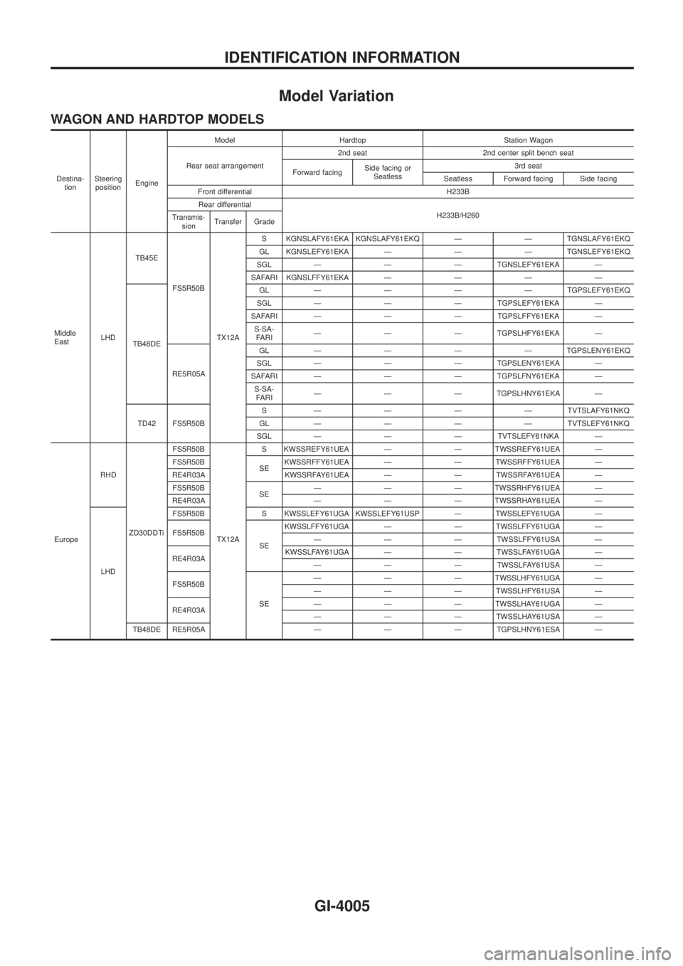
Model Variation
WAGON AND HARDTOP MODELS
Destina-
tionSteering
positionEngineModel Hardtop Station Wagon
Rear seat arrangement2nd seat 2nd center split bench seat
Forward facingSide facing or
Seatless3rd seat
Seatless Forward facing Side facing
Front differential H233B
Rear differential
H233B/H260
Transmis-
sionTransfer Grade
Middle
EastLHDTB45E
FS5R50B
TX12AS KGNSLAFY61EKA KGNSLAFY61EKQ Ð Ð TGNSLAFY61EKQ
GL KGNSLEFY61EKA Ð Ð Ð TGNSLEFY61EKQ
SGL Ð Ð Ð TGNSLEFY61EKA Ð
SAFARI KGNSLFFY61EKAÐÐÐÐ
TB48DEGLÐÐÐÐTGPSLEFY61EKQ
SGL Ð Ð Ð TGPSLEFY61EKA Ð
SAFARI Ð Ð Ð TGPSLFFY61EKA Ð
S-SA-
FARIÐ Ð Ð TGPSLHFY61EKA Ð
RE5R05AGLÐÐÐÐTGPSLENY61EKQ
SGL Ð Ð Ð TGPSLENY61EKA Ð
SAFARI Ð Ð Ð TGPSLFNY61EKA Ð
S-SA-
FARIÐ Ð Ð TGPSLHNY61EKA Ð
TD42 FS5R50BSÐÐÐÐTVTSLAFY61NKQ
GLÐÐÐÐTVTSLEFY61NKQ
SGL Ð Ð Ð TVTSLEFY61NKA Ð
EuropeRHD
ZD30DDTiFS5R50B
TX12AS KWSSREFY61UEA Ð Ð TWSSREFY61UEA Ð
FS5R50B
SEKWSSRFFY61UEA Ð Ð TWSSRFFY61UEA Ð
RE4R03A KWSSRFAY61UEA Ð Ð TWSSRFAY61UEA Ð
FS5R50B
SEÐ Ð Ð TWSSRHFY61UEA Ð
RE4R03A Ð Ð Ð TWSSRHAY61UEA Ð
LHDFS5R50B S KWSSLEFY61UGA KWSSLEFY61USP Ð TWSSLEFY61UGA Ð
FS5R50B
SEKWSSLFFY61UGA Ð Ð TWSSLFFY61UGA Ð
Ð Ð Ð TWSSLFFY61USA Ð
RE4R03AKWSSLFAY61UGA Ð Ð TWSSLFAY61UGA Ð
Ð Ð Ð TWSSLFAY61USA Ð
FS5R50B
SEÐ Ð Ð TWSSLHFY61UGA Ð
Ð Ð Ð TWSSLHFY61USA Ð
RE4R03AÐ Ð Ð TWSSLHAY61UGA Ð
Ð Ð Ð TWSSLHAY61USA Ð
TB48DE RE5R05A Ð Ð Ð TGPSLHNY61ESA Ð
IDENTIFICATION INFORMATION
GI-4005
Page 476 of 579
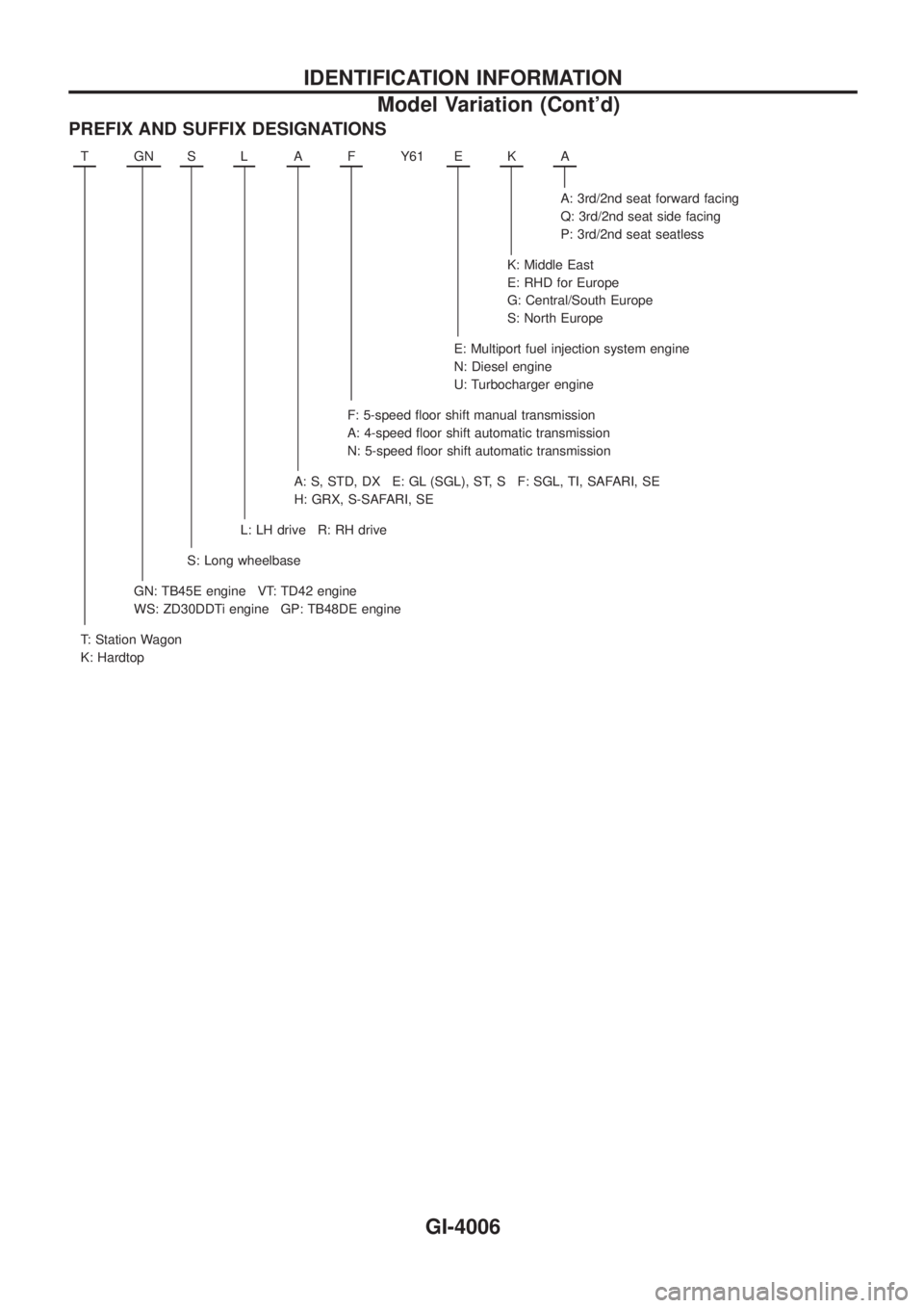
PREFIX AND SUFFIX DESIGNATIONS
TGNSLAFY61 EKA
A: 3rd/2nd seat forward facing
Q: 3rd/2nd seat side facing
P: 3rd/2nd seat seatless
K: Middle East
E: RHD for Europe
G: Central/South Europe
S: North Europe
E: Multiport fuel injection system engine
N: Diesel engine
U: Turbocharger engine
F: 5-speed ¯oor shift manual transmission
A: 4-speed ¯oor shift automatic transmission
N: 5-speed ¯oor shift automatic transmission
A: S, STD, DX E: GL (SGL), ST, S F: SGL, TI, SAFARI, SE
H: GRX, S-SAFARI, SE
L: LH drive R: RH drive
S: Long wheelbase
GN: TB45E engine VT: TD42 engine
WS: ZD30DDTi engine GP: TB48DE engine
T: Station Wagon
K: Hardtop
IDENTIFICATION INFORMATION
Model Variation (Cont'd)
GI-4006