Page 3663 of 3870
2. Turn the ignition switch to the "ON" position.
3. Check for Combination meter system diagnostic trouble code. (Refer to
COMBINATION METERS ASSEMBLY AND VEHICLE SPEED
).
4. Turn the ignition switch to the "LOCK" (OFF) position.
5. Disconnect scan tool MB991958.
Q: Is DTC U1102 set?
YES: Replace the hydraulic unit (integrated with ABS/TCL-ECU < FWD > or
TCL/ASC-ECU < AWD >). (Refer to HYDRAULIC UNIT
). Then go to Step
4.
NO: Replace the combination meter assembly. (Refer to COMBINATION
METER ASSEMBLY
). Then go to Step 4.
STEP 4. Retest the system
Q: Turn the ignition switch to the "ON" position. Do the "TCL OFF"
indicator light and the TCL work indicator light illuminate for three
seconds, and then go out after the engine starts?
YES: The procedure is complete.
NO: Return to Step 1 .
INSPECTION PROCEDURE 5: When the TCL Switch is Push On, TCL S
ystem does not Cancelled
.
2004 Mitsubishi Endeavor LS
2004 BRAKES Traction Control System (TCL) - Endeavor
Page 3670 of 3870

And Body
-Side Harness Connector
Courtesy of MITSUBISHI MOTOR SALES OF AMERICA.
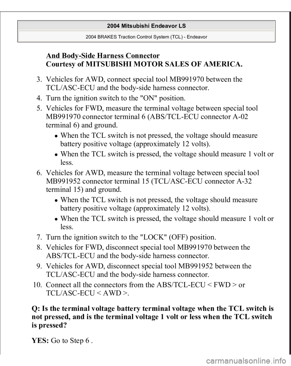
3. Vehicles for AWD, connect special tool MB991970 between the
TCL/ASC-ECU and the body-side harness connector.
4. Turn the ignition switch to the "ON" position.
5. Vehicles for FWD, measure the terminal voltage between special tool
MB991970 connector terminal 6 (ABS/TCL-ECU connector A-02
terminal 6) and ground.
When the TCL switch is not pressed, the voltage should measure
battery positive voltage (approximately 12 volts). When the TCL switch is pressed, the voltage should measure 1 volt or
less.
6. Vehicles for AWD, measure the terminal voltage between special tool
MB991952 connector terminal 15 (TCL/ASC-ECU connector A-32
terminal 15) and ground. When the TCL switch is not pressed, the voltage should measure
battery positive voltage (approximately 12 volts). When the TCL switch is pressed, the voltage should measure 1 volt or
less.
7. Turn the ignition switch to the "LOCK" (OFF) position.
8. Vehicles for FWD, disconnect special tool MB991970 between the
ABS/TCL-ECU and the body-side harness connector.
9. Vehicles for AWD, disconnect special tool MB991952 between the
TCL/ASC-ECU and the body-side harness connector.
10. Connect all the connectors from the ABS/TCL-ECU < FWD > or
TCL/ASC-ECU < AWD >.
Q: Is the terminal volta
ge batter
y terminal volta
ge when the TCL switch is
not
pressed, and is the terminal volta
ge 1 volt or less when the TCL switch
is pressed?
YES
: Go to Ste
p 6 .
2004 Mitsubishi Endeavor LS
2004 BRAKES Traction Control System (TCL) - Endeavor
Page 3685 of 3870

Courtesy of MITSUBISHI MOTOR SALES OF AMERICA
.
TROUBLESHOOTING HINTS (THE MOST LIKELY CAUSES FOR THIS CASE:)
Malfunction of the CAN bus line. Malfunction of the MFI system. Malfunction of the A/T system. Malfunction of the ABS/TCL-ECU < FWD > or TCL/ASC-ECU < AWD >.
DIAGNOSIS
Required Special Tool:
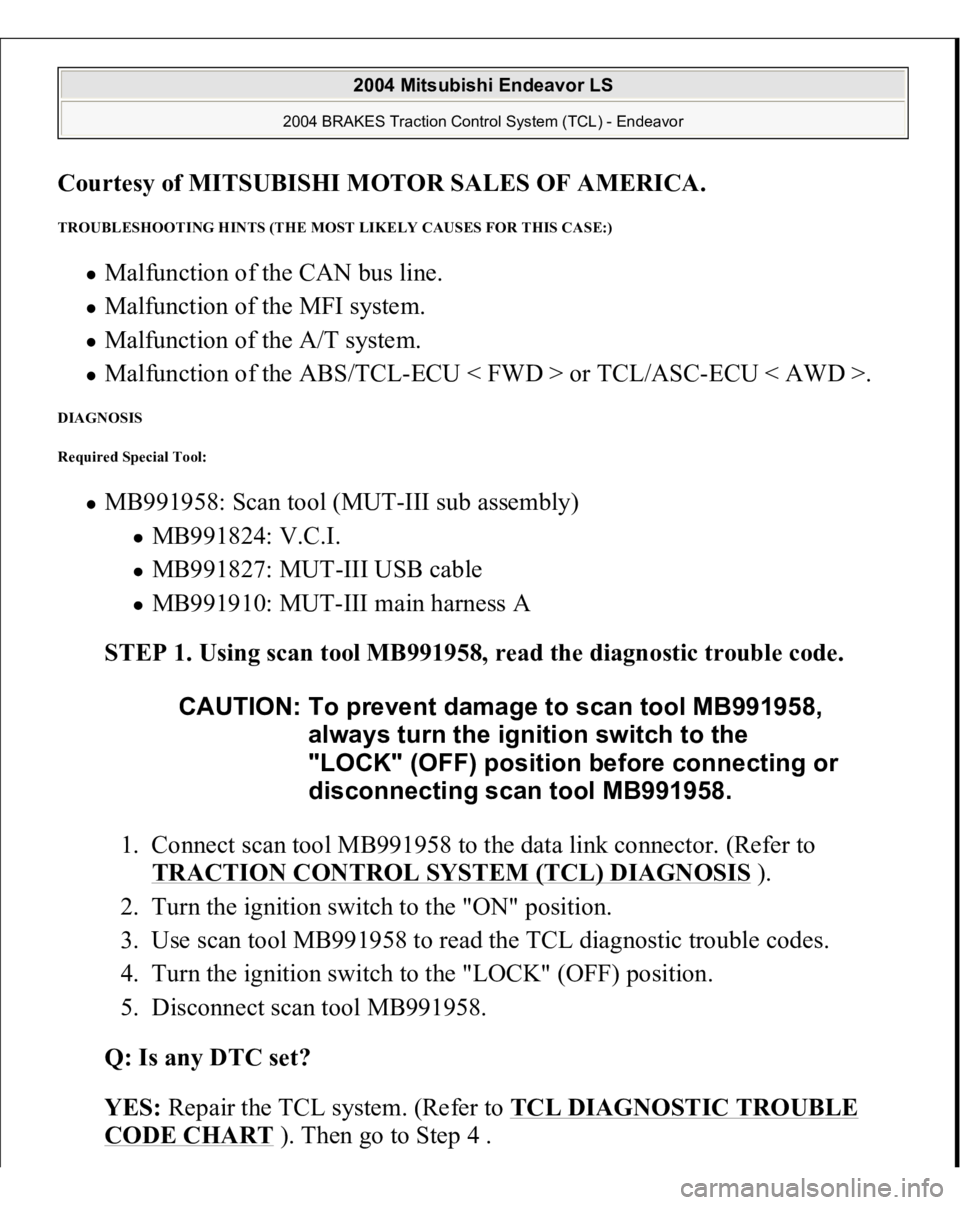
MB991958: Scan tool (MUT-III sub assembly)
MB991824: V.C.I. MB991827: MUT-III USB cable MB991910: MUT-III main harness A
STEP 1. Using scan tool MB991958, read the diagnostic trouble code.
1. Connect scan tool MB991958 to the data link connector. (Refer to
TRACTION CONTROL SYSTEM (TCL) DIAGNOSIS
).
2. Turn the ignition switch to the "ON" position.
3. Use scan tool MB991958 to read the TCL diagnostic trouble codes.
4. Turn the ignition switch to the "LOCK" (OFF) position.
5. Disconnect scan tool MB991958.
Q: Is any DTC set?
YES: Repair the TCL system. (Refer to TCL DIAGNOSTIC TROUBLE
CODE CHART
). Then go to Step 4 . CAUTION: To prevent damage to scan tool MB991958,
always turn the ignition switch to the
"LOCK" (OFF) position before connecting or
disconnecting scan tool MB991958.
2004 Mitsubishi Endeavor LS
2004 BRAKES Traction Control System (TCL) - Endeavor
Page 3686 of 3870
NO
: Go to Step 2.
STEP 2. Using scan tool MB991958, check actuator test item 09: Engine
TCL Drive.
CAUTION: To prevent damage to scan tool MB991958,
always turn the ignition switch to the
"LOCK" (OFF) position before connecting or
disconnecting scan tool MB991958.
2004 Mitsubishi Endeavor LS
2004 BRAKES Traction Control System (TCL) - Endeavor
Page 3688 of 3870

Courtesy of MITSUBISHI MOTOR SALES OF AMERICA
.
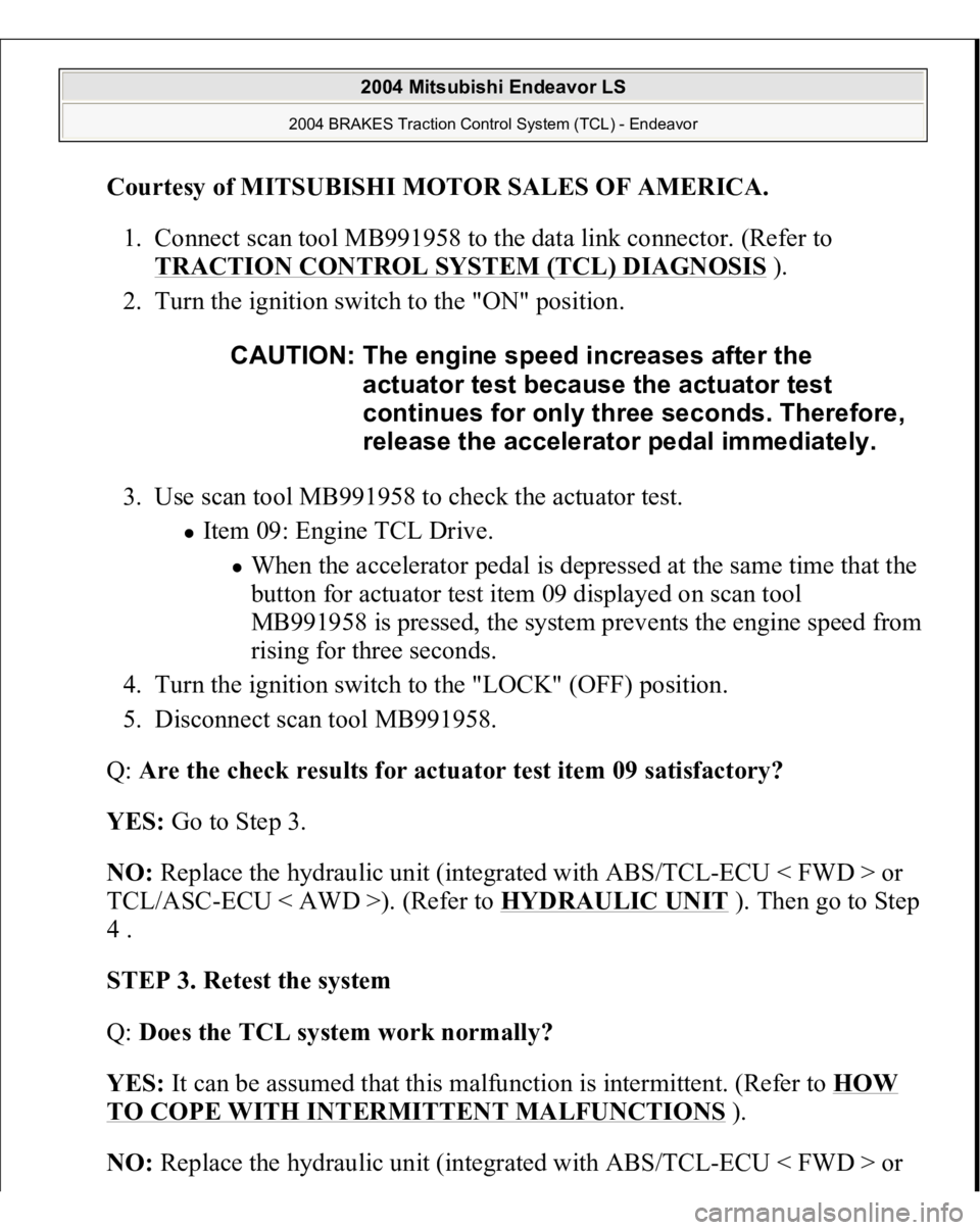
1. Connect scan tool MB991958 to the data link connector. (Refer to
TRACTION CONTROL SYSTEM (TCL) DIAGNOSIS ).
2. Turn the ignition switch to the "ON" position.
3. Use scan tool MB991958 to check the actuator test.
Item 09: Engine TCL Drive.
When the accelerator pedal is depressed at the same time that the
button for actuator test item 09 displayed on scan tool
MB991958 is pressed, the system prevents the engine speed from
rising for three seconds.
4. Turn the ignition switch to the "LOCK" (OFF) position.
5. Disconnect scan tool MB991958.
Q: Are the check results for actuator test item 09 satisfactory?
YES: Go to Step 3.
NO: Replace the hydraulic unit (integrated with ABS/TCL-ECU < FWD > or
TCL/ASC-ECU < AWD >). (Refer to HYDRAULIC UNIT
). Then go to Step
4 .
STEP 3. Retest the system
Q: Does the TCL system work normally?
YES: It can be assumed that this malfunction is intermittent. (Refer to HOW
TO COPE WITH INTERMITTENT MALFUNCTIONS
).
NO: Replace the hydraulic unit (integrated with ABS/TC
L-ECU < FWD > or CAUTION: The engine speed increases after the
actuator test because the actuator test
continues for only three seconds. Therefore,
release the accelerator pedal immediately.
2004 Mitsubishi Endeavor LS
2004 BRAKES Traction Control System (TCL) - Endeavor
Page 3692 of 3870
Fig. 56: Identifying Inspection Harness Connector
Courtesy of MITSUBISHI MOTOR SALES OF AMERICA.
Fig. 57:
Connector Terminal Table
Courtesy of MITSUBISHI MOTOR SALES OF AMERICA.
RESISTANCE AND CONTINUITY BETWEEN HARNESS-SIDE CONNECTOR TERMINALS Required Special Tool:
MB991970: ABS check harness
1. Disconnect the ABS/TCL-ECU connector A-02 and connect special tool
MB991970 to the A-02 body-side harness connector. Then turn the ignition
switch to the "LOCK"
(OFF
) position and checkin
g resistance and continuit
y.
NOTE: Do not measure terminal voltage for approximately three
seconds after the ignition switch is turned "ON". The
ABS/TCL-ECU performs the initial check during that period.
2004 Mitsubishi Endeavor LS
2004 BRAKES Traction Control System (TCL) - Endeavor
Page 3696 of 3870
Courtesy of MITSUBISHI MOTOR SALES OF AMERICA
.
Fig. 60: Connector Terminal Table
Courtesy of MITSUBISHI MOTOR SALES OF AMERICA.
RESISTANCE AND CONTINUITY BETWEEN HARNESS-SIDE CONNECTOR TERMINALS Required Special Tool:
MB991952: ABS check harness
1. Disconnect the TCL/ASC-ECU connector A-32 and connect special tool
MB991952 to the A-32 body-side harness connector. Then turn the ignition
switch to the "LOCK" (OFF) position and checking resistance and continuity.
2. Check the resistance and continuity between the terminals indicated in the table
below.
3. The terminal la
yout is shown in the illustration.
NOTE: Do not measure terminal voltage for approximately three
seconds after the ignition switch is turned "ON". The
TCL/ASC-ECU performs the initial check during that period.
2004 Mitsubishi Endeavor LS
2004 BRAKES Traction Control System (TCL) - Endeavor
Page 3700 of 3870
Fig. 63: Identifying Special Tools (2 Of 2)
Courtesy of MITSUBISHI MOTOR SALES OF AMERICA.
ON-VEHICLE SERVICE TCL INDICATOR LIGHT CHECK 1. Check that the "TCL OFF" indicator light and the TCL work indicator light
illuminate for three seconds when the ignition switch is turned to the "ON"
position.
2004 Mitsubishi Endeavor LS
2004 BRAKES Traction Control System (TCL) - Endeavor