Page 1508 of 3870
Fig. 12: Identifying Standard Value Specification Table
Courtesy of MITSUBISHI MOTOR SALES OF AMERICA.
3. Tighten the tension pulley fixing nut.
Tightening torque: 49+/-10 N.m (36+/-7 ft-lb)
POWER STEERING DRIVE BELT TENSION CHECK Check the drive belt tension by the following procedure. < WHEN USING SCAN TOOL MB991958 > Required Special Tools:
MB991958: Scan Tool (MUT-III Sub Assembly) [MB991824: Vehicle
Communication Interface (V.C.I.)] MB991668: Belt Tension Meter Set NOTE: Because the frequency depends on the belt material,
confirm Part No. shown on the reverse of the belt.
2004 Mitsubishi Endeavor Limited
2004 ENGINE Engine - Endeavor
Page 1541 of 3870
<< D >>POWER STEERING OIL PUMP REMOVAL Remove the power steering oil pump from the engine with the hose attached. << E >>ENGINE MOUNT REMOVAL 1. Support the engine with a garage jack.
Fig. 33: Supporting Engine
Courtesy of MITSUBISHI MOTOR SALES OF AMERICA.
assembly, and secure it with a cord or wire.
NOTE: Place the removed power steering oil pump in a place
where it will not be a hindrance when removing and
installing the engine assembly, and secure it with a cord or
wire.
2004 Mitsubishi Endeavor Limited
2004 ENGINE Engine - Endeavor
Page 1812 of 3870
Courtesy of MITSUBISHI MOTOR SALES OF AMERICA
.
REMOTE CONTROLLED RADIO SWITCH REMOVAL AND INSTALLATION Fig. 155: Removing/Installing Remote Controlled Radio Switch
Courtesy of MITSUBISHI MOTOR SALES OF AMERICA.
REMOVAL SERVICE POINT << A >> REMOTE CONTROLLED RADIO SWITCH REMOVAL Use a tool to hold the tabs on the remote controlled radio switch, and push out the
switch b
y your fin
ger.
WARNING:
Before removing the air bag module, refer to AIR BAG RESTRAINT SYSTEMS
).
When removing and installing the steering
wheel, do not let it bump against the air bag
module.
2004 Mitsubishi Endeavor LS
2004 BODY & ACCESSORIES Radio With Tape Player & Cd Player - Endeavor
Page 1939 of 3870
If the front suspension is faulty, the vehicle will not run straightforward or noise
will occur. Incorrect wheel alignment, malfunction of strut assembly, stabilizer bar,
coil spring, or worn or out-of-balance tires can cause these problems. FRONT SUSPENSION DIAGNOSIS TROUBLESHOOTING STRATEGY Use these steps to plan your diagnostic strategy. If you follow them carefully, you
will be sure that you have exhausted most of the possible ways to find a front
suspension fault.
1. Gather information from the customer.
2. Verify that the condition described by the customer exists.
3. Find and repair the malfunction by following the Symptom Chart and
Symptom Procedures.
4. Verify malfunction is eliminated. SYMPTOM CHART Fig. 2: Symptom Chart
Courtesy of MITSUBISHI MOTOR SALES OF AMERICA.
SYMPTOM PROCEDURES INSPECTION PROCEDURE 1: Steering Wheel Is Heavy, Vibrates Or Pulls To One Side DIAGNOSIS
STEP 1. Check the tires.
2004 Mitsubishi Endeavor LS 2004 SUSPENSION Front - Endeavor
Page 1945 of 3870
Fig. 4: Special Tools (2 Of 2)
Courtesy of MITSUBISHI MOTOR SALES OF AMERICA.
ON-VEHICLE SERVICE FRONT WHEEL ALIGNMENT CHECK AND ADJUSTMENT Measure wheel alignment with alignment equipment on a level surface. The front
sus
pension, steerin
g system, wheels, and tires should be serviced to normal
CAUTION: On vehicles with ASC, if the wheel alignment is
adjusted, always carry out steering wheel sensor
calibration (STEERING WHEEL SENSOR
CALIBRATION
). This is necessary because the
TCL/ASC-ECU should update the steering neutral
point.
2004 Mitsubishi Endeavor LS 2004 SUSPENSION Front - Endeavor
Page 1947 of 3870

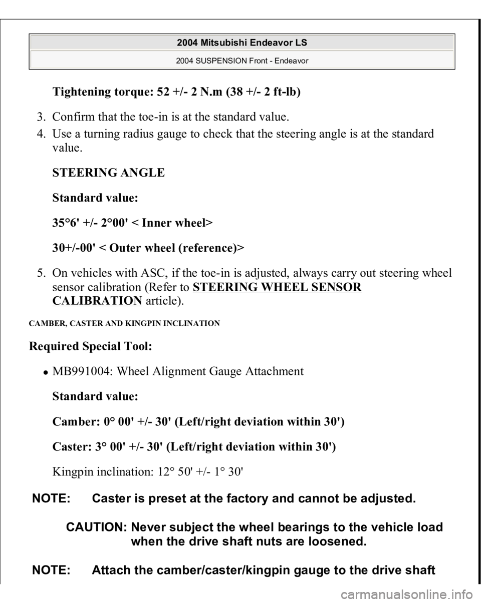
Tightening torque: 52 +/- 2 N.m (38 +
/-2 f
t-lb)
3. Confirm that the toe-in is at the standard value.
4. Use a turning radius gauge to check that the steering angle is at the standard
value.
STEERING ANGLE
Standard value:
35°6' +/- 2°00' < Inner wheel>
30+/-00' < Outer wheel (reference)>
5. On vehicles with ASC, if the toe-in is adjusted, always carry out steering wheel
sensor calibration (Refer to STEERING WHEEL SENSOR
CALIBRATION
article).
CAMBER, CASTER AND KINGPIN INCLINATION Required Special Tool:
MB991004: Wheel Alignment Gauge Attachment
Standard value:
Camber: 0° 00' +/- 30' (Left/right deviation within 30')
Caster: 3° 00' +/- 30' (Left/right deviation within 30')
Kingpin inclination: 12° 50' +/- 1° 30'
NOTE: Caster is preset at the factory and cannot be adjusted.
CAUTION: Never subject the wheel bearings to the vehicle load
when the drive shaft nuts are loosened.
NOTE: Attach the camber/caster/kingpin gauge to the drive shaft
2004 Mitsubishi Endeavor LS 2004 SUSPENSION Front - Endeavor
Page 1975 of 3870
Fig. 32: Installing Special Tool MB991897
Courtesy of MITSUBISHI MOTOR SALES OF AMERICA.
2. Turn the bolt and knob as necessary to make the jaws of special tool
MB991897 parallel, tighten the bolt by hand and confirm that the jaws are still
parallel.
Fig. 33: Using Special Tool MB991897
Courtesy of MITSUBISHI MOTOR SALES OF AMERICA.
3. Tighten the bolt with a wrench to disconnect the tie rod end.
REMOVAL SERVICE POINT <> STEERING GEAR AND STEERING COLUMN SHAFT DISCONNECTION
NOTE: When adjusting the jaws in parallel, make sure the knob
is in the position shown in the figure.
2004 Mitsubishi Endeavor LS 2004 SUSPENSION Front - Endeavor
Page 1976 of 3870
1. Remove the steering gear and steering column shaft connecting bolt.
2. Pinch the steering column shaft clip with pliers, and pull up the shaft towards
the direction shown in illustration to disengage the steering column shaft from
the steering gear.
Fig. 34: Disengaging Steering Column Shaft From Steering Gear
Courtesy of MITSUBISHI MOTOR SALES OF AMERICA.
NOTE: If the steering column shaft is removed accidentally,
remove the steering column assembly and be sure to
insert the steering column shaft into the steering
column as shown in the figure.
2004 Mitsubishi Endeavor LS 2004 SUSPENSION Front - Endeavor