Page 1618 of 3870
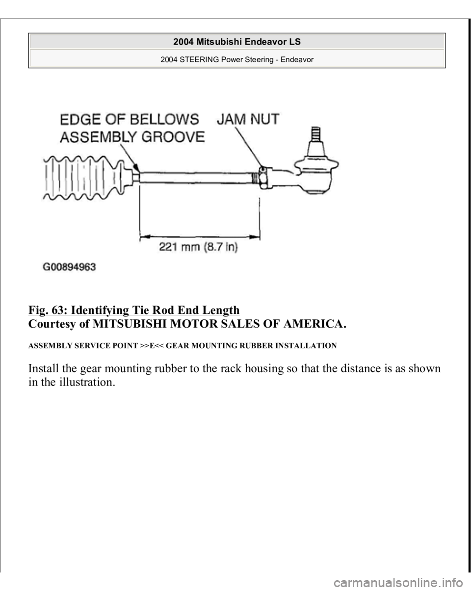
Fig. 98: Checking Rod
Courtesy of MITSUBISHI MOTOR SALES OF AMERICA.
3. While holding the auto-tensioner with your hand, press the end of the pushrod
against a metal surface (such as the cylinder block) with a force of 98 - 196 N
(22 - 44 pound) and measure how far the pushrod is pushed in.
Standard value: Within 1 mm (0.04 inch)
A: Length when no force is applied
B: Length when force is applied
A - B: Movement in
2004 Mitsubishi Endeavor Limited
2004 ENGINE Engine - Endeavor
Page 1911 of 3870
2004 DRIVE AXLES
Axle Shafts - Front - Endeavor
DESCRIPTION The axle shafts consist Birfield Joint (BJ)-Pillow Tripod Joint (PTJ), Birfield Joint
(BJ)-Double Offset Joint (DOJ), and Birfield Joint (BJ)-Tripod Joint (TJ) Constant
Velocity (CV) joints with solid metal shafts. Due to the use of the inner shaft and
bracket assembly, the right and left drive shafts are approximately the same length.
This reduces noise, vibration, and torque steer. LUBRICATION AWD For lubrication
points, see Fig. 1
or Fig. 2
.
2004 Mitsubishi Endeavor LS
2004 DRIVE AXLES Axle Shafts - Front - Endeavor
2004 Mitsubishi Endeavor LS
2004 DRIVE AXLES Axle Shafts - Front - Endeavor
Page 1955 of 3870
Page 2705 of 3870
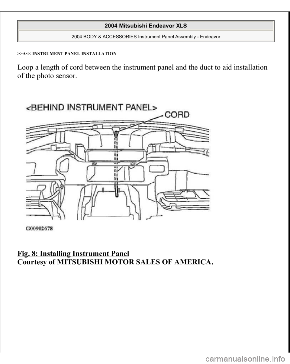
>>A<< INSTRUMENT PANEL INSTALLATIONLoop a length of cord between the instrument panel and the duct to aid installation
of the photo sensor.
Fig. 8: Installing Instrument Panel
Courtes
y of MITSUBISHI MOTOR SALES OF AMERICA
.
2004 Mitsubishi Endeavor XLS
2004 BODY & ACCESSORIES Instrument Panel Assembly - Endeavor
Page 2905 of 3870
equation, and use a new bellows band to repeat steps (2) to (3)
.
W = 5.5 mm (0.22 inch) - A
[Example: if (A) is 2.3 mm (0.09 inch), (W) is 3.2 mm (0.13 inch).]
Fig. 62: Checking Crimped Width (A)
Courtesy of MITSUBISHI MOTOR SALES OF AMERICA.
ASSEMBLY SERVICE POINT >>D<< TIE ROD END/JAM NUT INSTALLATION Screw in the tie rod end to achieve the right and left length as shown in illustration.
Lock with the jam nut. NOTE: The locking nuts must be tightened securely only after the
steering gear is installed and toe is adjusted.
2004 Mitsubishi Endeavor LS
2004 STEERING Power Steering - Endeavor
Page 2906 of 3870
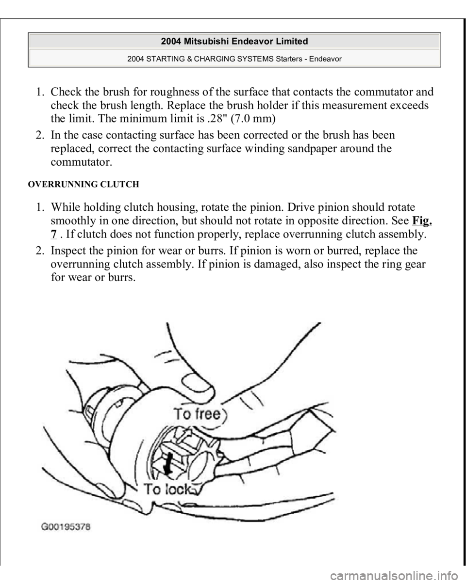
Fig. 63: Identifying Tie Rod End Length
Courtesy of MITSUBISHI MOTOR SALES OF AMERICA.
ASSEMBLY SERVICE POINT >>E<< GEAR MOUNTING RUBBER INSTALLATION Install the gear mounting rubber to the rack housing so that the distance is as shown
in the illustration.
2004 Mitsubishi Endeavor LS
2004 STEERING Power Steering - Endeavor
Page 3543 of 3870
1. Check the brush for roughness of the surface that contacts the commutator and
check the brush length. Replace the brush holder if this measurement exceeds
the limit. The minimum limit is .28" (7.0 mm)
2. In the case contacting surface has been corrected or the brush has been
replaced, correct the contacting surface winding sandpaper around the
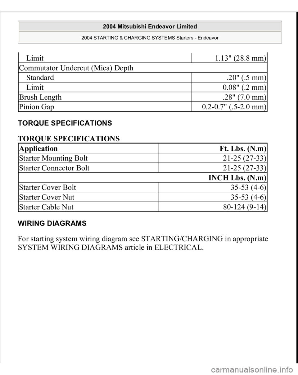
commutator. OVERRUNNING CLUTCH 1. While holding clutch housing, rotate the pinion. Drive pinion should rotate
smoothly in one direction, but should not rotate in opposite direction. See Fig.
7 . If clutch does not function properly, replace overrunning clutch assembly.
2. Inspect the pinion for wear or burrs. If pinion is worn or burred, replace the
overrunning clutch assembly. If pinion is damaged, also inspect the ring gear
for wear or burrs.
2004 Mitsubishi Endeavor Limited
2004 STARTING & CHARGING SYSTEMS Starters - Endeavor
Page 3552 of 3870
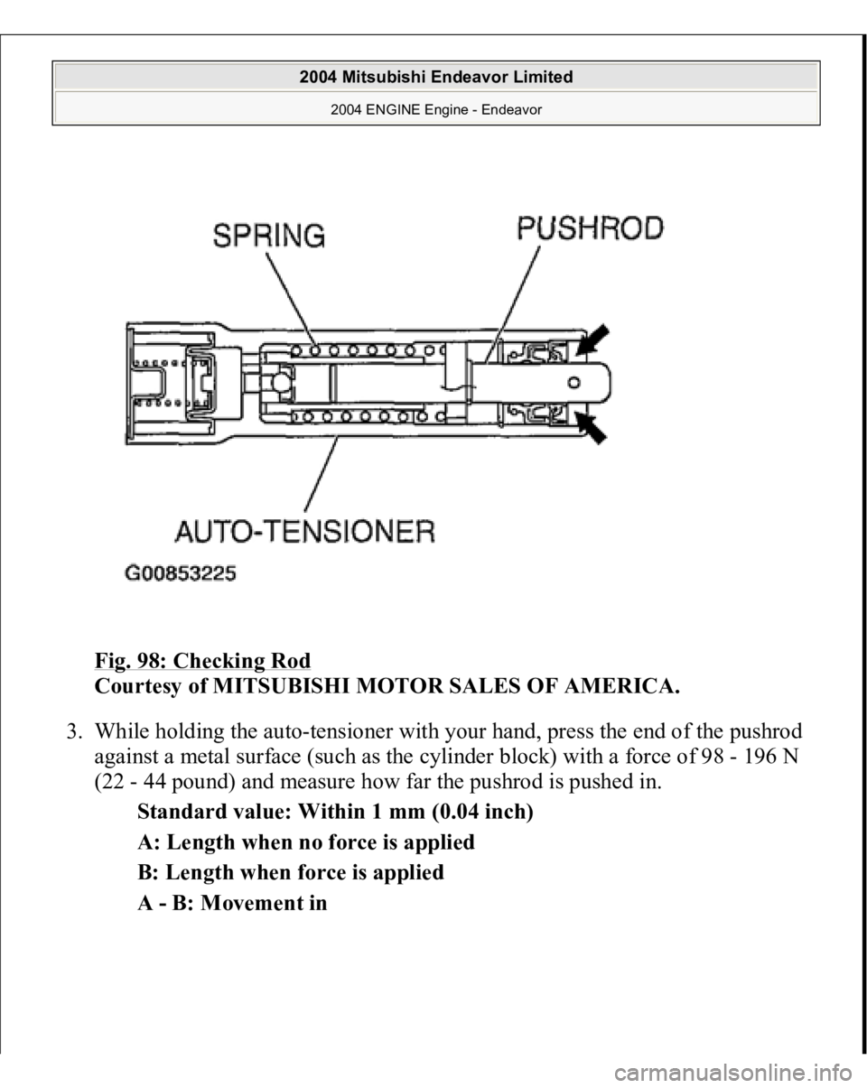
TORQUE SPECIFICATIONS TORQUE SPECIFICATIONS WIRING DIAGRAMS For starting system wiring diagram see STARTING/CHARGING in appropriate
SYSTEM WIRING DIAGRAMS article in ELECTRICAL.
Limit
1.13" (28.8 mm)
Commutator Undercut (Mica) DepthStandard
.20" (.5 mm)
Limit
0.08" (.2 mm)
Brush Length
.28" (7.0 mm)
Pinion Gap
0.2-0.7" (.5-2.0 mm)
Application
Ft. Lbs. (N.m)
Starter Mounting Bolt
21-25 (27-33)
Starter Connector Bolt
21-25 (27-33)
INCH Lbs. (N.m)
Starter Cover Bolt
35-53 (4-6)
Starter Cover Nut
35-53 (4-6)
Starter Cable Nut
80-124 (9-14)
2004 Mitsubishi Endeavor Limited
2004 STARTING & CHARGING SYSTEMS Starters - Endeavor
Page:
< prev 1-8 9-16 17-24
![MITSUBISHI ENDEAVOR 2004 Service Repair Manual equation, and use a new bellows band to repeat steps (2) to (3)
.
W = 5.5 mm (0.22 inch) - A
[Example: if (A) is 2.3 mm (0.09 inch), (W) is 3.2 mm (0.13 inch).]
Fig. 62: Checking Crimped Width (](/manual-img/19/57105/w960_57105-2904.png "MITSUBISHI ENDEAVOR 2004 Service Repair Manual equation, and use a new bellows band to repeat steps (2) to (3)
.
W = 5.5 mm (0.22 inch) - A
[Example: if (A) is 2.3 mm (0.09 inch), (W) is 3.2 mm (0.13 inch).]
Fig. 62: Checking Crimped Width (")