Page 3473 of 3870
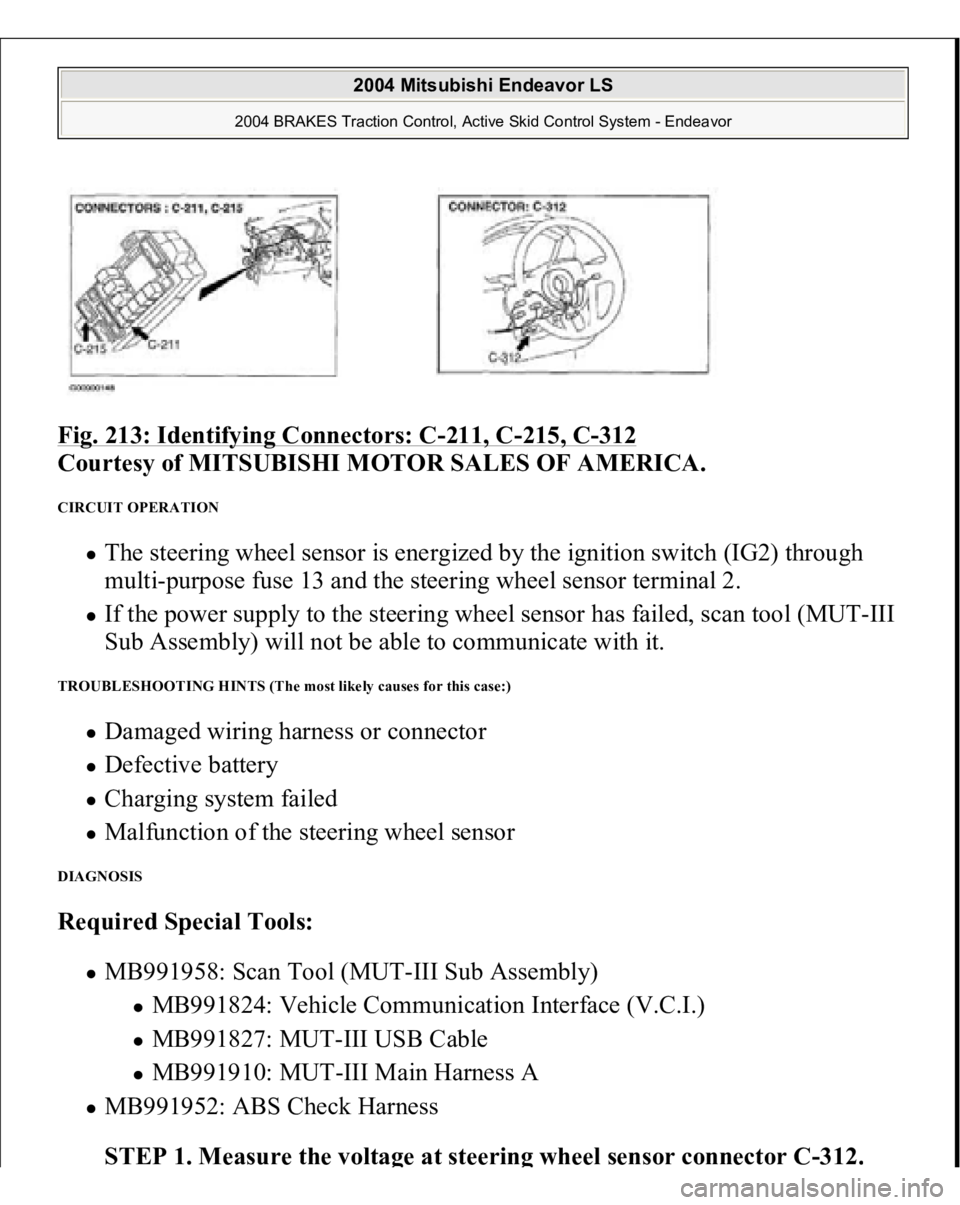
Fig. 213: Identifying Connectors: C
-211, C
-215, C
-312
Courtesy of MITSUBISHI MOTOR SALES OF AMERICA.
CIRCUIT OPERATION
The steering wheel sensor is energized by the ignition switch (IG2) through
multi-purpose fuse 13 and the steering wheel sensor terminal 2. If the power supply to the steering wheel sensor has failed, scan tool (MUT-III
Sub Assembly) will not be able to communicate with it.
TROUBLESHOOTING HINTS (The most likely causes for this case:)
Damaged wiring harness or connector Defective battery Charging system failed Malfunction of the steering wheel sensor
DIAGNOSIS Required Special Tools:
MB991958: Scan Tool (MUT-III Sub Assembly)
MB991824: Vehicle Communication Interface (V.C.I.) MB991827: MUT-III USB Cable MB991910: MUT-III Main Harness A
MB991952: ABS Check Harness
STEP 1. Measure the volta
ge at steerin
g wheel sensor connector C-312
.
2004 Mitsubishi Endeavor LS
2004 BRAKES Traction Control, Active Skid Control System - Endeavor
Page 3476 of 3870
Fig. 214: Measuring Voltage At Steering Wheel Sensor Connector C
-
312
Courtesy of MITSUBISHI MOTOR SALES OF AMERICA.
Q: Is battery positive voltage (approximately 12 volts) present?
YES: Go to Step 3.
NO: Go to Step 2.
STEP 2. Check the following connectors.
Junction block connector C-211 and C-215
2004 Mitsubishi Endeavor LS
2004 BRAKES Traction Control, Active Skid Control System - Endeavor
Page 3478 of 3870
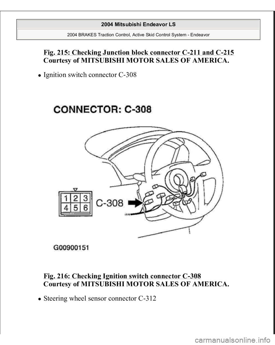
Fig. 215: Checking Junction block connector C
-211 and C
-215
Courtesy of MITSUBISHI MOTOR SALES OF AMERICA.
Ignition switch connector C-308
Fig. 216: Checking Ignition switch connector C
-308
Courtesy of MITSUBISHI MOTOR SALES OF AMERICA.
Steerin
g wheel sensor connector C-312
2004 Mitsubishi Endeavor LS
2004 BRAKES Traction Control, Active Skid Control System - Endeavor
Page 3479 of 3870
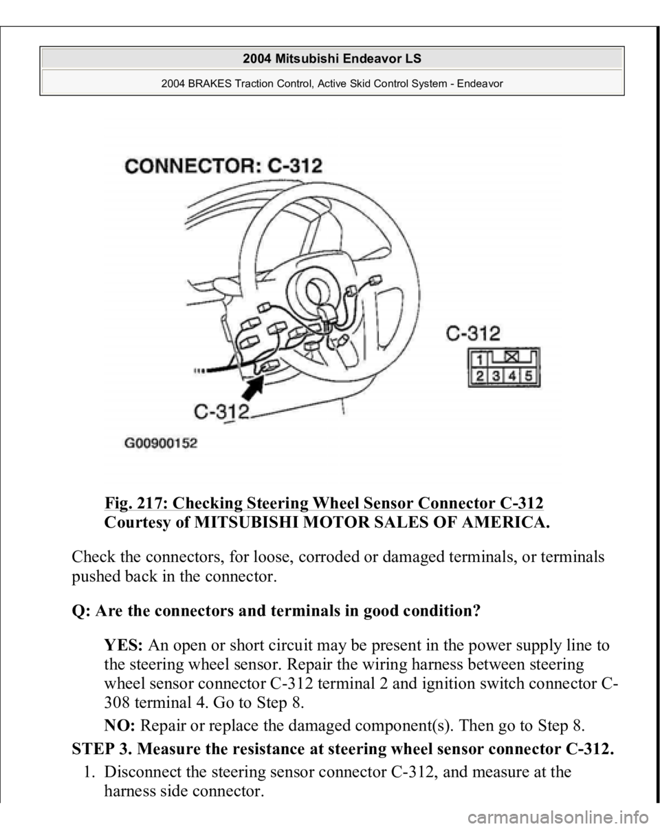
Fig. 217: Checking Steering Wheel Sensor Connector C
-312
Courtesy of MITSUBISHI MOTOR SALES OF AMERICA.
Check the connectors, for loose, corroded or damaged terminals, or terminals
pushed back in the connector.
Q: Are the connectors and terminals in good condition?
YES: An open or short circuit may be present in the power supply line to
the steering wheel sensor. Repair the wiring harness between steering
wheel sensor connector C-312 terminal 2 and ignition switch connector C-
308 terminal 4. Go to Step 8.
NO: Repair or replace the damaged component(s). Then go to Step 8.
STEP 3. Measure the resistance at steering wheel sensor connector C-312.
1. Disconnect the steering sensor connector C-312, and measure at the
harness side connector.
2004 Mitsubishi Endeavor LS
2004 BRAKES Traction Control, Active Skid Control System - Endeavor
Page 3482 of 3870
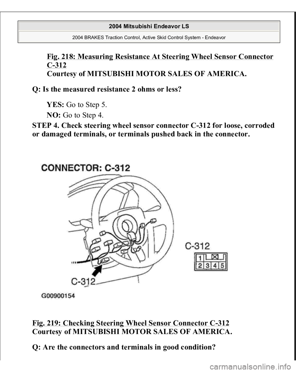
Fig. 218: Measuring Resistance At Steering Wheel Sensor Connector C-312
Courtesy of MITSUBISHI MOTOR SALES OF AMERICA.
Q: Is the measured resistance 2 ohms or less?
YES: Go to Step 5.
NO: Go to Step 4.
STEP 4. Check steering wheel sensor connector C-312 for loose, corroded
or damaged terminals, or terminals pushed back in the connector.
Fig. 219: Checking Steering Wheel Sensor Connector C
-312
Courtesy of MITSUBISHI MOTOR SALES OF AMERICA.
Q: Are the connectors and terminals in good condition?
2004 Mitsubishi Endeavor LS
2004 BRAKES Traction Control, Active Skid Control System - Endeavor
Page 3483 of 3870
YES: An open circuit may be present in the ground circuit. Repair the
wiring harness between steering wheel sensor connector C-312 terminals 5
and the body ground. Then go to Step 8.
NO: Repair or replace the damaged component(s). Then go to Step 8.
STEP 5. Check the battery.
Check the battery (Refer to BATTERY TEST
).
Q: Is the battery in good condition?
YES: Go to Step 6.
NO: Charge or replace the battery. Then go to Step 8.
STEP 6. Check the charging system.
Check the charging system (Refer to GENERATORS & REGULATORS
).
Q: Is the charging system in good condition?
YES: Go to Step 7.
NO: Repair or replace the charging system component(s). Then go to Step
8.
STEP 7. Retest the system.
Q: Can the steering wheel sensor communicate with the scan tool (MUT-
III Sub Assembly)?
YES: It can be assumed that this malfunction is intermittent. Refer to
HOW TO COPE WITH INTERMITTENT MALFUNCTIONS
.
NO: Replace the steering wheel sensor. Then go to Step 8.
STEP 8. Retest the system.
Q: Can the steering wheel sensor communicate with the scan tool (MUT-
III Sub Assembly)?
YES: The
procedure is com
plete.
2004 Mitsubishi Endeavor LS
2004 BRAKES Traction Control, Active Skid Control System - Endeavor
Page 3508 of 3870
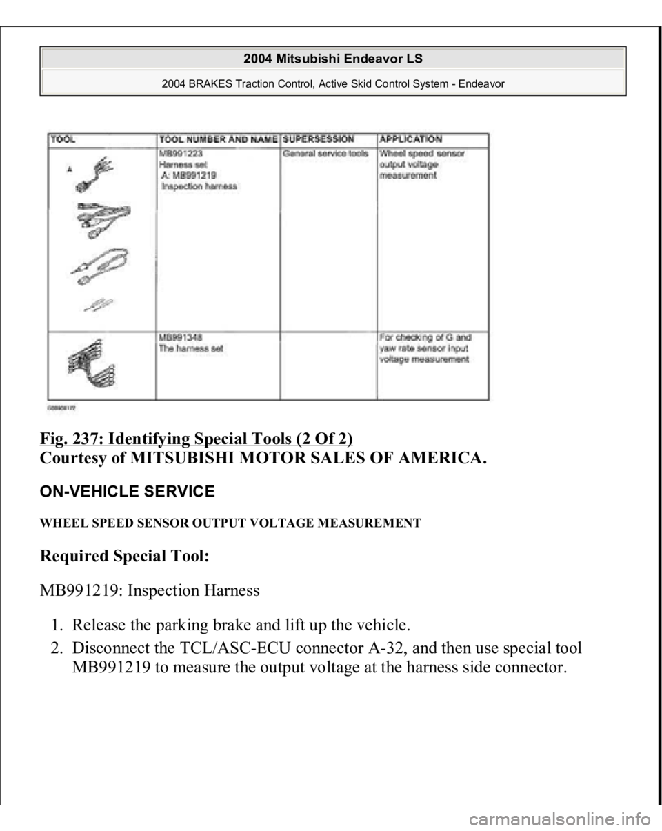
Fig. 237: Identifying Special Tools (2 Of 2)
Courtesy of MITSUBISHI MOTOR SALES OF AMERICA.
ON-VEHICLE SERVICE WHEEL SPEED SENSOR OUTPUT VOLTAGE MEASUREMENT Required Special Tool:
MB991219: Inspection Harness
1. Release the parking brake and lift up the vehicle.
2. Disconnect the TCL/ASC-ECU connector A-32, and then use special tool
MB991219 to measure the out
put volta
ge at the harness side connector.
2004 Mitsubishi Endeavor LS
2004 BRAKES Traction Control, Active Skid Control System - Endeavor
Page 3511 of 3870
3. Manually turn the wheel to be measured 1/2 to 1 turn/second. Measure the
output voltage with a voltmeter or oscilloscope.
Output voltage:
Minimal voltmeter reading: 42 mV Maximum voltmeter reading: 300 mV Minimal oscilloscope reading: 120 mV Maximum oscilloscope reading: 600 mV
Probable causes of low output voltage Wheel speed sensor pole piece-to-Wheel speed rotor clearance too large Faulty Wheel speed sensor
4. To observe the waveform with an oscilloscope: Front Wheels: Shift into "D" range and drive the wheels. Rear Wheels: Turn the wheels manually at a constant speed NOTE: Check the connection of the sensor harness and
connector before using the oscilloscope.
NOTE: The output waveform is low when the wheel speed is
low. Similarly, it will be higher as the wheel speed
increases. Waveform may also be observed by driving
the vehicle.
2004 Mitsubishi Endeavor LS
2004 BRAKES Traction Control, Active Skid Control System - Endeavor