Page 440 of 3870

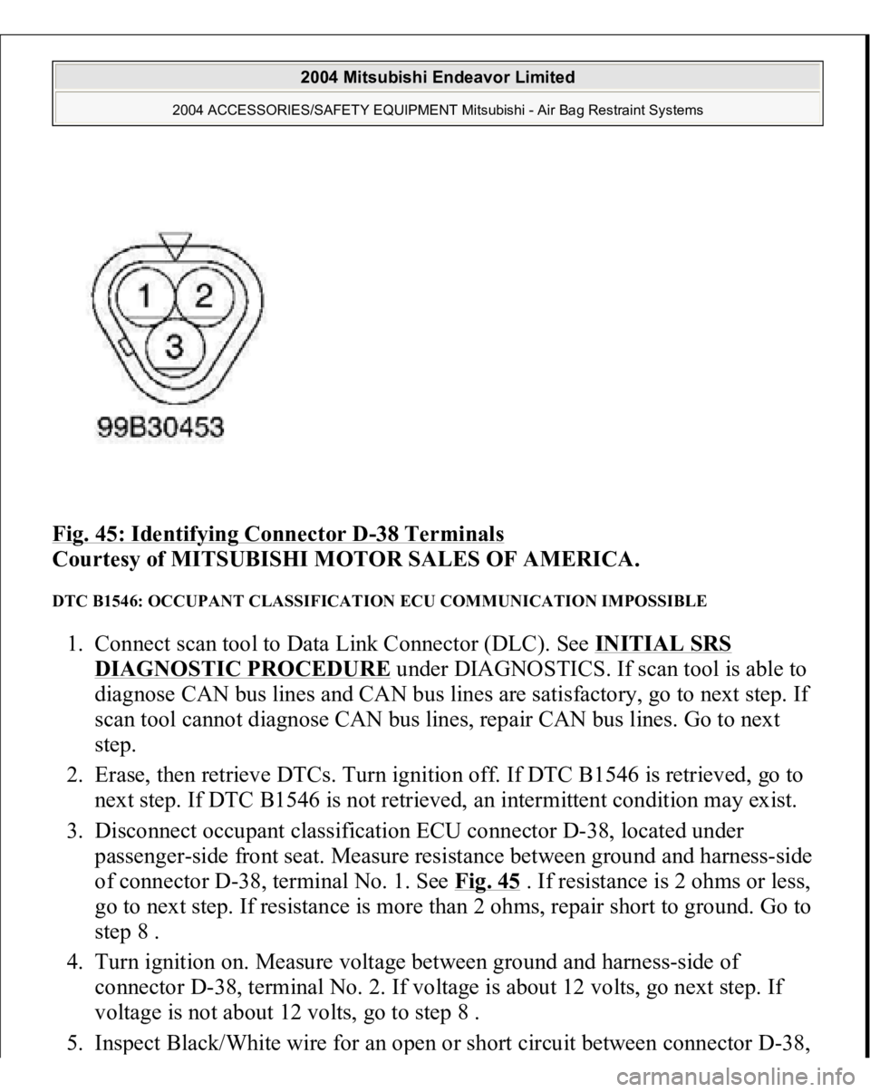
Fig. 45: Identifying Connector D
-38 Terminals
Courtesy of MITSUBISHI MOTOR SALES OF AMERICA.
DTC B1546: OCCUPANT CLASSIFICATION ECU COMMUNICATION IMPOSSIBLE 1. Connect scan tool to Data Link Connector (DLC). See INITIAL SRS
DIAGNOSTIC PROCEDURE
under DIAGNOSTICS. If scan tool is able to
diagnose CAN bus lines and CAN bus lines are satisfactory, go to next step. If
scan tool cannot diagnose CAN bus lines, repair CAN bus lines. Go to next
step.
2. Erase, then retrieve DTCs. Turn ignition off. If DTC B1546 is retrieved, go to
next step. If DTC B1546 is not retrieved, an intermittent condition may exist.
3. Disconnect occupant classification ECU connector D-38, located under
passenger-side front seat. Measure resistance between ground and harness-side
of connector D-38, terminal No. 1. See Fig. 45
. If resistance is 2 ohms or less,
go to next step. If resistance is more than 2 ohms, repair short to ground. Go to
step 8 .
4. Turn ignition on. Measure voltage between ground and harness-side of
connector D-38, terminal No. 2. If voltage is about 12 volts, go next step. If
voltage is not about 12 volts, go to step 8 .
5. Ins
pect Black/White wire for an o
pen or short circuit between connector D-38,
2004 Mitsubishi Endeavor Limited
2004 ACCESSORIES/SAFETY EQUIPMENT Mitsubishi - Air Bag Restraint Systems
Page 441 of 3870

terminal No. 2 and ignition switch connector C-308, terminal No. 2. If wire is
okay, go to step 8 . If wire is not okay, replace wire harness between occupant
classification ECU and ignition switch connector C-308. Go to step 8 .
6. Disconnect SRS ECU connector C-25. See SRS ELECTRONIC CONTROL UNIT (SRS ECU)
under REMOVAL & INSTALLATION. See Fig. 30
.
Inspect Sky Blue wire for an open or short circuit between connector D-38,
terminal No. 3 and SRS ECU connector C-25, terminal No. 66. See Fig. 33
. If
wire is okay, reconnect SRS components. Erase, then retrieve DTCs. If DTC
B1545 is retrieved, replace front seat slide adjuster. Go to next step. If wire
harness is not okay, replace wire harness. Go to step 8 .
7. Erase DTCs. Turn ignition on. If DTC B1546 is retrieved, replace SRS ECU.
Go to next step. If DTC B1546 is not retrieved, diagnosis is complete.
8. Erase, then retrieve DTCs. If DTC B1546 is retrieved, go to step 1 . If DTC
B1546 is not retrieved, system is normal at this time.
DTC B1547: CUT OFF FOR PASSENGER-SIDE AIR BAG MODULE 1. Connect scan tool to Data Link Connector (DLC). See INITIAL SRS
DIAGNOSTIC PROCEDURE
under DIAGNOSTICS. If scan tool is able to
diagnose CAN bus lines and CAN bus lines are satisfactory, go to next step. If
scan tool cannot diagnose CAN bus lines, repair CAN bus lines. Go to next
step.
2. Erase, then retrieve DTCs. Turn ignition off. If DTC B1547 is retrieved, go to
next step. If DTC B1547 is not retrieved, an intermittent condition may exist.
3. If DTCs other than DTC B1457 are retrieved, diagnose indicated DTC. See
DIAGNOSTIC TROUBLE CODES (DTCS) IDENTIFICATION WITH
SINGLE
-STAGE AIR BAG SYSTEM
table. If only DTC B1547 is
retrieved, go to next step.
4. Using scan tool, erase, then retrieve DTCs. If DTC B1547 is retrieved, replace
SRS ECU. See SRS ELECTRONIC CONTROL UNIT (SRS ECU)
under
REMOVAL & INSTALLATION. If DTC B1547 is not retrieved, diagnosis is
complete.
DTC B1552: CHANGING CIRCUIT SHORT 1. Connect scan tool to Data Link Connector
(DLC
). SeeINITIAL SRS
2004 Mitsubishi Endeavor Limited
2004 ACCESSORIES/SAFETY EQUIPMENT Mitsubishi - Air Bag Restraint Systems
Page 443 of 3870

diagnose CAN bus lines and CAN bus lines are satisfactory, go to next step. If
scan tool cannot diagnose CAN bus lines, repair CAN bus lines. Go to next
step.
2. Erase, then retrieve DTCs. If DTC B1555 is retrieved, replace SRS ECU. See
SRS ELECTRONIC CONTROL UNIT (SRS ECU)
under REMOVAL &
INSTALLATION. If DTC B1555 is not retrieved, an intermittent condition
may exist.
DTC B1556: SEAT SLIDE SENSOR MALFUNCTION 1. Connect scan tool to Data Link Connector (DLC). See INITIAL SRS
DIAGNOSTIC PROCEDURE
under DIAGNOSTICS. If scan tool is able to
diagnose CAN bus lines and CAN bus lines are satisfactory, go to next step. If
scan tool cannot diagnose CAN bus lines, repair CAN bus lines. Go to next
step.
2. Erase, then retrieve DTCs. Turn ignition off. If DTC B1556 is retrieved, go to
next step. If DTC B1556 is not retrieved, an intermittent condition may exist.
3. Replace seat slide sensor. See SEAT SLIDE SENSOR
under REMOVAL &
INSTALLATION. Check for DTCs. If DTC B1556 is retrieved, replace SRS
ECU. See SRS ELECTRONIC CONTROL UNIT (SRS ECU)
under
REMOVAL & INSTALLATION. If DTC B1556 is not retrieved, procedure is
complete.
DTCB1557: SRS ECU ASIC 1. Connect scan tool to Data Link Connector (DLC). See INITIAL SRS
DIAGNOSTIC PROCEDURE
under DIAGNOSTICS. If scan tool is able to
diagnose CAN bus lines and CAN bus lines are satisfactory, go to next step. If
scan tool cannot diagnose CAN bus lines, repair CAN bus lines. Go to next
step.
2. Erase, then retrieve DTCs. If DTC B1557 is retrieved, replace SRS ECU. See
SRS ELECTRONIC CONTROL UNIT (SRS ECU)
under REMOVAL &
INSTALLATION. If DTC B1557 is not retrieved, an intermittent condition
may exist.
DTCB1558: OCCUPANT CLASSIFICATION ECU ID CORD MALFUNCTION
2004 Mitsubishi Endeavor Limited
2004 ACCESSORIES/SAFETY EQUIPMENT Mitsubishi - Air Bag Restraint Systems
Page 696 of 3870
Dt : Measured specific gravity
t: Measured temperature
Fig. 1: Battery Visual Inspection (1)
Courtesy of MITSUBISHI MOTOR SALES OF AMERICA.
BATTERY VISUAL INSPECTION (2) Make sure the ignition switch is in "LOCK" (OFF) position and all battery feed
accessories are OFF.
1. Disconnect the negative cable from the battery before disconnecting the
positive cable.
WARNING:Care should be taken in the event the battery
2004 Mitsubishi Endeavor Limited 2004 ELECTRICAL Battery - Endeavor
Page 730 of 3870
1. Turn the ignition switch to the "LOCK" (OFF) position, depress the brake
pedal two or three times. After eliminating the vacuum in the brake booster,
press the pedal down by hand, and confirm that the amount of movement
before resistance is met (free play) is within the standard value range.
Standard value: 3 - 8 mm (0.12 - 0.31 inch)
2004 Mitsubishi Endeavor LS
2004 BRAKES Basic Brake System - Endeavor
Page 794 of 3870
If condenser fan motor is defective, replace it.
Fig. 2: Testing Condenser Fan Motor
Courtesy of MITSUBISHI MOTOR SALES OF AMERICA.
FAN CONTROL MODULE 1. Remove the fan control module connector. See Fig. 3
.
2. Turn the ignition switch to the ON position. Check for battery voltage between
terminals No. 1 and 3. See Fig. 3
.
3. Reconnect the fan control module connector and disconnect the condenser fan
motor connector. See Fig. 4
.
4. Measure voltage between the fan control module (side connector) terminals.
Voltage should be 1V or less.
CAUTION: Stay clear of the fan when starts running.
2004 Mitsubishi Endeavor Limited
2004 ENGINE COOLING Electric Cooling Fans - Endeavor
Page 799 of 3870

Technical Descriptio
n
The cause could be a malfunction of the fan control module power supply or
ground circuit. The cause could also be a malfunction of the fan control module or the PCM.
Troubleshooting Hints
Malfunction of fusible link. Malfunction of fan control relay. Malfunction of MFI relay. Malfunction of radiator fan motor. Malfunction of condenser fan motor. Malfunction of fan control module. Malfunction of PCM. Damaged wiring harness or connector.
Diagnosis 1. Disconnect fan control module connector A-23. See Fig. 7
. Measure for
voltage between terminal No. 3 (harness side of the connector) and ground
when ignition switch is turned to the ON position. If battery voltage is not
achieved, go to next step. If battery voltage is achieved, go to step 8 .
2. Check fan control relay. See FAN CONTROL RELAY under
COMPONENTS TESTS. If fan control relay is okay, go to next step. If fan
control relay is not okay, replace it and retest.
3. Check the MFI relay. See MULTI
-PORT FUEL INJECTION (MFI)
RELAY
under COMPONENT TESTS. If MFI relay is okay, go to next step. If
MFI relay is not okay, replace it and retest.
4. Check for harness damage in Black/Yellow wire between fusible link No. 2
and terminal No. 4 of fan control relay connector A-10X. See Fig. 8
. If wire is
okay, go to next step. If wire is damaged, repair or replace as necessary and
retest.
5. Check for harness damage in Blue wire between terminal No. 2 of fan control
rela
y connector
A-10X and terminal No. 3 of fan control module connector A-
2004 Mitsubishi Endeavor Limited
2004 ENGINE COOLING Electric Cooling Fans - Endeavor
Page 801 of 3870
the radiator fan is operating is less than 0.7V, go to next step. If the voltage
when the radiator fan is operating is 0.7V or more, go to step 13 .
12. Check the Blue/Orange wire between terminal No. 10 of PCM connector B-18
(Green) and terminal No. 2 of fan control module connector A-23. See Fig. 7
and Fig. 11
. If wiring is damaged repair or replace as necessary and retest. If
wiring is okay, go to next step.
13. Pull out terminal No. 10 of PCM connector B-18 (Green). See Fig. 11
. Turn
the ignition switch to the ON position. If the radiator fan motor and condenser
fan motor operate, replace the PCM and retest. If the radiator and the
condenser fan motor do not operate, replace the radiator fan motor and retest.
Fig. 7: Locating Fan Control Module Connector (A
-23)
Courtesy of MITSUBISHI MOTOR SALES OF AMERICA.
NOTE: Do not disconnect PCM connector B-18 (Green).
2004 Mitsubishi Endeavor Limited
2004 ENGINE COOLING Electric Cooling Fans - Endeavor