2004 MITSUBISHI ENDEAVOR ignition
[x] Cancel search: ignitionPage 404 of 3870
10. Reconnect all SRS components. Activate air bag system. Using scan tool,
retrieve DTCs. If DTC B1486 is retrieved, go to step 1 . If DTC B1486 is not
retrieved, system is normal at this time.
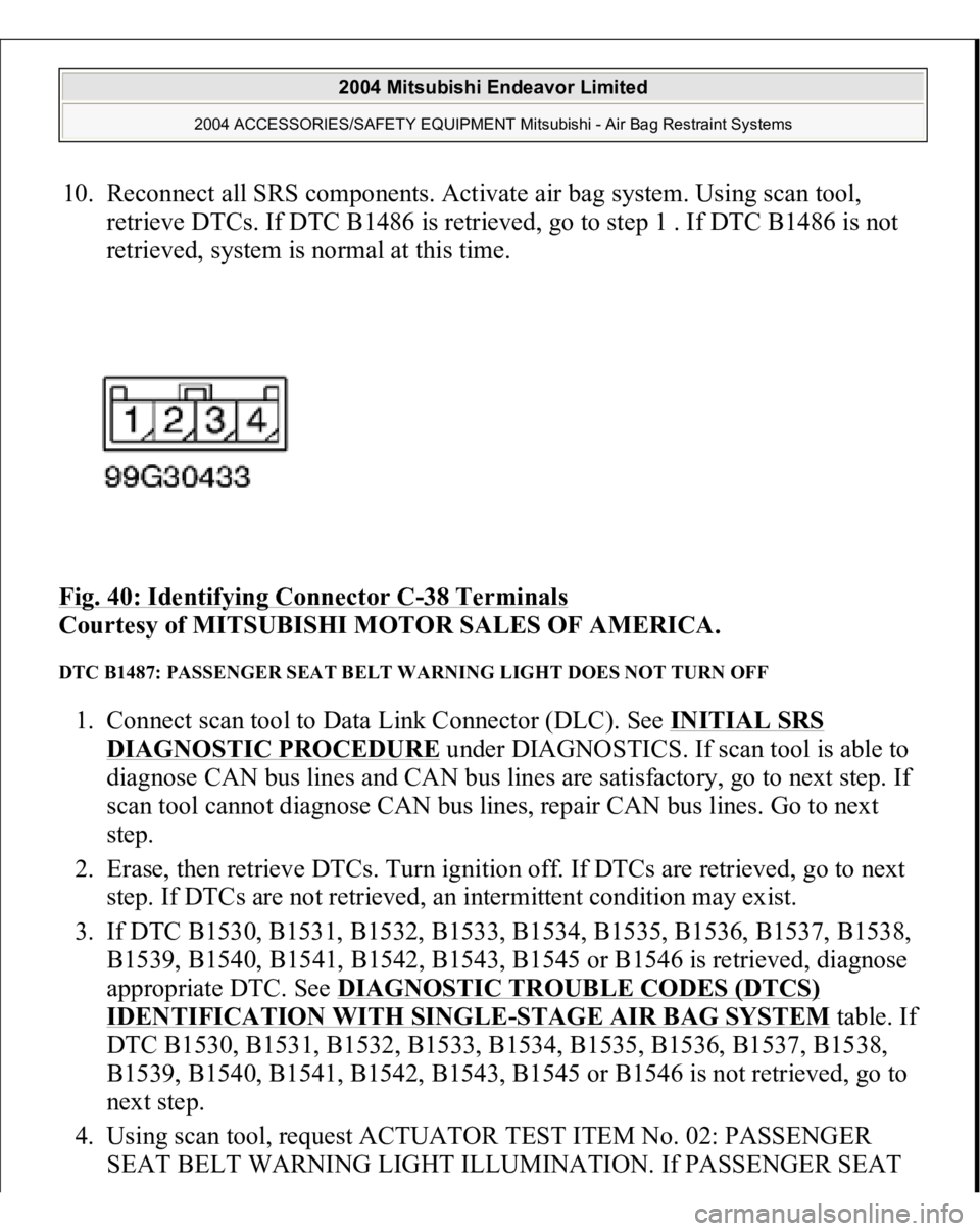
Fig. 40: Identifying Connector C
-38 Terminals
Courtesy of MITSUBISHI MOTOR SALES OF AMERICA.
DTC B1487: PASSENGER SEAT BELT WARNING LIGHT DOES NOT TURN OFF 1. Connect scan tool to Data Link Connector (DLC). See INITIAL SRS
DIAGNOSTIC PROCEDURE
under DIAGNOSTICS. If scan tool is able to
diagnose CAN bus lines and CAN bus lines are satisfactory, go to next step. If
scan tool cannot diagnose CAN bus lines, repair CAN bus lines. Go to next
step.
2. Erase, then retrieve DTCs. Turn ignition off. If DTCs are retrieved, go to next
step. If DTCs are not retrieved, an intermittent condition may exist.
3. If DTC B1530, B1531, B1532, B1533, B1534, B1535, B1536, B1537, B1538,
B1539, B1540, B1541, B1542, B1543, B1545 or B1546 is retrieved, diagnose
appropriate DTC. See DIAGNOSTIC TROUBLE CODES (DTCS)
IDENTIFICATION WITH SINGLE
-STAGE AIR BAG SYSTEM
table. If
DTC B1530, B1531, B1532, B1533, B1534, B1535, B1536, B1537, B1538,
B1539, B1540, B1541, B1542, B1543, B1545 or B1546 is not retrieved, go to
next step.
4. Using scan tool, request ACTUATOR TEST ITEM No. 02: PASSENGER
SEAT BELT WARNING LIGHT ILLUMINATION. If PASSENGER SEAT
2004 Mitsubishi Endeavor Limited
2004 ACCESSORIES/SAFETY EQUIPMENT Mitsubishi - Air Bag Restraint Systems
Page 405 of 3870
BELT warning light comes on and goes off after 7 seconds, go to next step. If
PASSENGER SEAT BELT warning light does not come on and go off after 7
seconds, replace passenger seat belt warning light. Go to step 6 .
5. Inspect Pink wire between connector C-38, terminal No. 3 and SRS ECU
connector C-26, terminal No. 42, for an open circuit. See Fig. 30
. If an open
circuit is not found, reconnect SRS components. Erase, then retrieve DTCs. If
DTC B1487 is retrieved, replace SRS ECU. See SRS ELECTRONIC
CONTROL UNIT (SRS ECU)
under REMOVAL & INSTALLATION. Go
to next step. If an open circuit is found, repair wire as necessary. See WIRE
REPAIR
. Go to next step.
6. Reconnect all SRS components. Activate air bag system. Using scan tool,
retrieve DTCs. If DTC B1487 is retrieved, go to step 1 . If DTC B1487 is not
retrieved, system is normal at this time.
DTC B1488: PASSENGER AIR BAG OFF INDICATOR CIRCUIT MALFUNCTION 1. Connect scan tool to Data Link Connector (DLC). See INITIAL SRS
DIAGNOSTIC PROCEDURE
under DIAGNOSTICS. If scan tool is able to
diagnose CAN bus lines and CAN bus lines are satisfactory, go to next step. If
scan tool cannot diagnose CAN bus lines, repair CAN bus lines. Go to next
step.
2. Erase, then retrieve DTCs. If DTC B1488 is retrieved, go to DTC B1489:
PASSENGER AIR BAG OFF INDICATOR LIGHT DOES NOT ILLUMINATE
. If DTC B1488 is not retrieved, an intermittent condition may
exist.
DTC B1489: PASSENGER AIR BAG OFF INDICATOR LIGHT DOES NOT ILLUMINATE 1. Connect scan tool to Data Link Connector (DLC). See INITIAL SRS
DIAGNOSTIC PROCEDURE
under DIAGNOSTICS. If scan tool is able to
diagnose CAN bus lines and CAN bus lines are satisfactory, go to next step. If
scan tool cannot diagnose CAN bus lines, repair CAN bus lines. Go to next
step.
2. Erase, then retrieve DTCs. Turn ignition off. If DTCs are retrieved, go to next
step. If DTCs are not retrieved, an intermittent condition may exist.
3. If DTC B1540, B1541, B1542, B1543, B1545 or B1546 is retrieved, dia
gnose
2004 Mitsubishi Endeavor Limited
2004 ACCESSORIES/SAFETY EQUIPMENT Mitsubishi - Air Bag Restraint Systems
Page 406 of 3870
appropriate DTC. See DIAGNOSTIC TROUBLE CODES (DTCS) IDENTIFICATION WITH SINGLE
-STAGE AIR BAG SYSTEM
table. If
DTC B1540, B1541, B1542, B1543, B1545 or B1546 is not retrieved, go to
next step.
4. Visually inspect PASSENGER AIR BAG OFF indicator connector C-37. See
Fig. 30
. If connector C-37 is connected correctly, go to next step. If connector
C-37 is not connected correctly, properly connect connector. Go to step 10 .
5. Disconnect connector C-37. Measure voltage between ground and connector
C-37, terminal No. 1 (Black/White wire). See Fig. 41
. If voltage is not about
12 volts, go to next step. If voltage is about 12 volts, go to step 7 .
6. Inspect Black/White wire between terminal No. 1 of connector C-37 and
terminal No. 2 of ignition switch connector C-308, including junction block
connectors C-211 and C-215. See Fig. 22
. If wire is okay, go to next step. If
wire is not okay, repair as necessary. See WIRE REPAIR
. Go to step 10 .
7. Inspect SRS ECU connector C-26. See SRS ELECTRONIC CONTROL
UNIT (SRS ECU)
under REMOVAL & INSTALLATION. If SRS ECU
connector C-26 is connected correctly, go to next step. If SRS ECU connector
C-26 is not connected correctly, properly connect connector. Go to step 10 .
8. Check Blue/Yellow wire between connector C-37, terminal No. 3 and SRS
ECU connector C-26, terminal No. 21, for damage, shorts or open circuits. See
Fig. 33
. If wire is okay, go to next step. If wire is not okay, repair as
necessary. Go to step 10 .
9. Disconnect negative battery cable. Disconnect SRS ECU connector C-26.
Connect negative battery cable. Connect a jumper wire between ground and
SRS ECU connector C-26, terminal No. 21. If PASSENGER AIR BAG OFF
warning light does not illuminate, replace PASSENGER AIR BAG OFF
warning light assembly. Go to next step. If PASSENGER AIR BAG OFF
warning light illuminates, erase, then retrieve DTCs. If DTC B1489 is
retrieved, replace SRS ECU. Go to next step.
10. Reconnect all SRS components. Activate air bag system. Using scan tool,
retrieve DTCs. If DTC B1489 is retrieved, go to step 1 . If DTC B1489 is not
retrieved, s
ystem is normal at this time.
2004 Mitsubishi Endeavor Limited
2004 ACCESSORIES/SAFETY EQUIPMENT Mitsubishi - Air Bag Restraint Systems
Page 407 of 3870
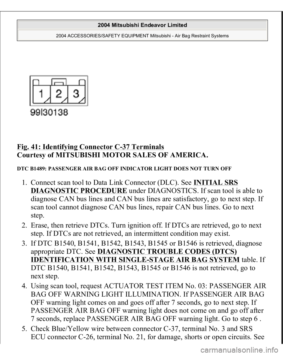
Fig. 41: Identifying Connector C
-37 Terminals
Courtesy of MITSUBISHI MOTOR SALES OF AMERICA.
DTC B1489: PASSENGER AIR BAG OFF INDICATOR LIGHT DOES NOT TURN OFF 1. Connect scan tool to Data Link Connector (DLC). See INITIAL SRS
DIAGNOSTIC PROCEDURE
under DIAGNOSTICS. If scan tool is able to
diagnose CAN bus lines and CAN bus lines are satisfactory, go to next step. If
scan tool cannot diagnose CAN bus lines, repair CAN bus lines. Go to next
step.
2. Erase, then retrieve DTCs. Turn ignition off. If DTCs are retrieved, go to next
step. If DTCs are not retrieved, an intermittent condition may exist.
3. If DTC B1540, B1541, B1542, B1543, B1545 or B1546 is retrieved, diagnose
appropriate DTC. See DIAGNOSTIC TROUBLE CODES (DTCS)
IDENTIFICATION WITH SINGLE
-STAGE AIR BAG SYSTEM
table. If
DTC B1540, B1541, B1542, B1543, B1545 or B1546 is not retrieved, go to
next step.
4. Using scan tool, request ACTUATOR TEST ITEM No. 03: PASSENGER AIR
BAG OFF WARNING LIGHT ILLUMINATION. If PASSENGER AIR BAG
OFF warning light comes on and goes off after 7 seconds, go to next step. If
PASSENGER AIR BAG OFF warning light does not come on and go off after
7 seconds, replace PASSENGER AIR BAG OFF warning light. Go to step 6 .
5. Check Blue/Yellow wire between connector C-37, terminal No. 3 and SRS
ECU connector C-26, terminal No. 21, for damage, shorts or open circuits. See
2004 Mitsubishi Endeavor Limited
2004 ACCESSORIES/SAFETY EQUIPMENT Mitsubishi - Air Bag Restraint Systems
Page 408 of 3870
Fig. 33
& Fig. 41
. If wire is okay, erase, then retrieve DTCs. If DTC B1489 is
retrieved, replace SRS ECU. Go to next step. If wire is not okay, repair as
necessary. Go to next step.
6. Reconnect all SRS components. Activate air bag system. Using scan tool,
retrieve DTCs. If DTC B1489 is retrieved, go to step 1 . If DTC B1489 is not
retrieved, system is normal at this time.
DTC B1490: PASSENGER-SIDE AIR BAG MODULE SECOND-STAGE SHORT CIRCUIT 1. Connect scan tool to Data Link Connector (DLC). See INITIAL SRS
DIAGNOSTIC PROCEDURE
under DIAGNOSTICS. If scan tool is able to
diagnose CAN bus lines and CAN bus lines are satisfactory, go to next step. If
scan tool cannot diagnose CAN bus lines, repair CAN bus lines. Go to next
step.
2. Erase, then retrieve DTCs. Turn ignition off. If DTC B1490 is retrieved, go to
next step. If DTC B1490 is not retrieved, an intermittent condition may exist.
3. Turn ignition on. If DTC B1519 is retrieved by scan tool, go to next step. If
DTC B1519 is not retrieved by scan tool, go to step 5 .
4. Inspect SRS ECU connector C-26. See SRS ELECTRONIC CONTROL
UNIT (SRS ECU)
under REMOVAL & INSTALLATION. See Fig. 30
. If
connectors are connected correctly, go to next step. If connectors are not
connected correctly, reconnect correctly. Go to step 9 .
5. Disconnect negative battery cable. Disconnect, then reconnect SRS ECU
connector C-26 and passenger-side air bag module C-09. Connect negative
battery cable. Using scan tool, erase, then retrieve DTCs. If DTC B1490 is
retrieved, go to next step. If DTC B1490 is not retrieved, intermittent condition
may have existed.
6. Disconnect negative battery cable. Disconnect passenger-side air bag module
connector C-09. See PASSENGER
-SIDE AIR BAG MODULE
under
REMOVAL & INSTALLATION. Connect Load Resistor (MB991865) to
Load Resistor Adapter (MB991866). Insert load resistor adapter leads into
harness-side terminals No. 3 (Yellow/Pink wire) and No. 4 (Yellow/Gray wire)
of connector C-09. See Fig. 35
. Connect negative battery cable. Erase, then
retrieve DTCs. If DTC B1490 is retrieved, go to next step. If DTC B1490 is
not retrieved, re
place
passen
ger-side air ba
g module.
2004 Mitsubishi Endeavor Limited
2004 ACCESSORIES/SAFETY EQUIPMENT Mitsubishi - Air Bag Restraint Systems
Page 409 of 3870
7. Disconnect negative battery cable. Remove load resistor and load resistor
adapter from passenger-side air bag module connector C-09. Disconnect SRS
ECU connector. Release SRS ECU connector shorting bar using a cable tie.
Measure resistance between SRS ECU connector terminals No. 31
(Yellow/Pink wire) and No. 30 (Yellow/Gray wire). If continuity exits, go to
next step. If continuity does not exist, reconnect SRS components. Erase, then
retrieve DTCs. If DTC B1490 is retrieved, replace SRS ECU. Go to step 9 .
8. Replace wire harness between SRS ECU and passenger-side air bag module.
Go to next step.
9. Reconnect all SRS components. Activate air bag system. Using scan tool,
retrieve DTCs. If DTC B1490 is retrieved, go to step 1 . If DTC B1490 is not
retrieved, system is normal at this time. DTC B1491: PASSENGER-SIDE AIR BAG MODULE SECOND-STAGE OPEN CIRCUIT 1. Connect scan tool to Data Link Connector (DLC). See INITIAL SRS
DIAGNOSTIC PROCEDURE
under DIAGNOSTICS. If scan tool is able to
diagnose CAN bus lines and CAN bus lines are satisfactory, go to next step. If
scan tool cannot diagnose CAN bus lines, repair CAN bus lines. Go to next
step.
2. Erase, then retrieve DTCs. Turn ignition off. If DTC B1491 is retrieved, go to
next step. If DTC B1491 is not retrieved, an intermittent condition may exist.
3. Disconnect negative battery cable. Disconnect passenger-side air bag module
connector C-09. See PASSENGER
-SIDE AIR BAG MODULE
under
REMOVAL & INSTALLATION. See Fig. 30
. Connect Load Resistor
(MB991865) to Load Resistor Adapter (MB991866). Insert load resistor
adapter leads into harness-side terminals No. 3 (Yellow/Pink wire) and No. 4
(Yellow/GRay wire) of connector C-09. See Fig. 35
. Connect negative battery
cable. Erase, then retrieve DTCs. If DTC B1491 is retrieved, go to next step. If
DTC B1491 is not retrieved, replace passenger-side air bag module. Go to step
5 .
4. Disconnect negative battery cable. Remove load resistor and load resistor
adapter from connector C-09. Disconnect SRS ECU connector. See SRS
ELECTRONIC CONTROL UNIT (SRS ECU)
under REMOVAL &
INSTALLATION. Release SRS ECU connector shortin
g bar usin
g a cable tie.
2004 Mitsubishi Endeavor Limited
2004 ACCESSORIES/SAFETY EQUIPMENT Mitsubishi - Air Bag Restraint Systems
Page 410 of 3870
Measure resistance of Yellow/Pink wire between SRS ECU connector terminal
No. 31 and passenger-side air bag module connector C-09, terminal No. 3. See
Fig. 33
& Fig. 35
. Measure resistance of Yellow/Gray wire between SRS
ECU connector terminal No. 30 and passenger-side air bag module connector
C-09, terminal No. 4. If resistance is more than 2 ohms in either wire, replace
wire harness between SRS ECU and passenger-side air bag module. Go to next
step. If resistance is less than 2 ohms in both wires, reconnect SRS
components. Erase, then retrieve DTCs. If DTC B1491 is retrieved, replace
SRS ECU. Go to next step
5. Reconnect all SRS components. Activate air bag system. Using scan tool,
retrieve DTCs. If DTC B1491 is retrieved, go to step 1 . If DTC B1491 is not
retrieved, system is normal at this time.
DTC B1492: PASSENGER-SIDE AIR BAG MODULE SECOND-STAGE CIRCUIT SHORT TO
VOLTAGE 1. Connect scan tool to Data Link Connector (DLC). See INITIAL SRS
DIAGNOSTIC PROCEDURE
under DIAGNOSTICS. If scan tool is able to
diagnose CAN bus lines and CAN bus lines are satisfactory, go to next step. If
scan tool cannot diagnose CAN bus lines, repair CAN bus lines. Go to next
step.
2. Erase, then retrieve DTCs. Turn ignition off. If DTC B1492 is retrieved, go to
next step. If DTC B1492 is not retrieved, an intermittent condition may exist.
3. Disconnect negative battery cable. Disconnect passenger-side air bag module
connector C-09. See PASSENGER
-SIDE AIR BAG MODULE
under
REMOVAL & INSTALLATION. See Fig. 30
. Connect Load Resistor
(MB991865) to Load Resistor Adapter (MB991866). Insert load resistor
adapter leads into harness-side terminals No. 3 (Yellow/Pink wire) and No. 4
(Yellow/Gray wire) of connector C-09. See Fig. 35
. Connect negative battery
cable. Erase, then retrieve DTCs. If DTC B1492 is retrieved, go to next step. If
DTC B1492 is not retrieved, replace passenger-side air bag module. Go to step
5 .
4. Disconnect negative battery cable. Remove load resistor and load resistor
adapter from passenger-side air bag module connector C-09. Disconnect SRS
ECU connector C-26. See SRS ELECTRONIC CONTROL UNIT (SRS
ECU
) under REMOVAL & INSTALLATION. Release SRS ECU connecto
r
2004 Mitsubishi Endeavor Limited
2004 ACCESSORIES/SAFETY EQUIPMENT Mitsubishi - Air Bag Restraint Systems
Page 411 of 3870
shorting bar using a cable tie. Measure voltage between ground and SRS ECU
connector terminals No. 31 (Yellow/Pink wire) and No. 30 (Yellow/Gray
wire). See Fig. 33
. If voltage is measured at either terminal, go to next step. If
voltage is not measured at either terminal, reconnect SRS components. Erase,
then retrieve DTCs. If DTC B1492 is retrieved, replace SRS ECU. Go to step
6 .
5. Replace wire harness between SRS ECU and passenger-side air bag module.
Go to next step.
6. Reconnect all SRS components. Activate air bag system. Using scan tool,
retrieve DTCs. If DTC B1492 is retrieved, go to step 1 . If DTC B1492 is not
retrieved, system is normal at this time.
DTC B1493: PASSENGER-SIDE AIR BAG MODULE SECOND-STAGE SHORT TO GROUND 1. Connect scan tool to Data Link Connector (DLC). See INITIAL SRS
DIAGNOSTIC PROCEDURE
under DIAGNOSTICS. If scan tool is able to
diagnose CAN bus lines and CAN bus lines are satisfactory, go to next step. If
scan tool cannot diagnose CAN bus lines, repair CAN bus lines. Go to next
step.
2. Erase, then retrieve DTCs. Turn ignition off. If DTC B1493 is retrieved, go to
next step. If DTC B1493 is not retrieved, an intermittent condition may exist.
3. Disconnect negative battery cable. Disconnect passenger-side air bag module
connector C-09. See PASSENGER
-SIDE AIR BAG MODULE
under
REMOVAL & INSTALLATION. See Fig. 30
. Connect Load Resistor
(MB991865) to Load Resistor Adapter (MB991866). Insert load resistor
adapter leads into harness-side terminals No. 3 (Yellow/Pink wire) and No. 4
(Yellow/Gray wire) of connector C-09. See Fig. 35
. Connect negative battery
cable. Erase, then retrieve DTCs. If DTC B1493 is retrieved, go to next step. If
DTC B1493 is not retrieved, replace passenger-side air bag module. Go to step
6 .
4. Disconnect negative battery cable. Remove load resistor and load resistor
adapter from passenger-side air bag module connector C-09. Disconnect SRS
ECU connector C-26. See SRS ELECTRONIC CONTROL UNIT (SRS
ECU)
under REMOVAL & INSTALLATION. Release SRS ECU connector
shorting bar usin
g a cable tie. Measure resistance
between
ground and SRS
2004 Mitsubishi Endeavor Limited
2004 ACCESSORIES/SAFETY EQUIPMENT Mitsubishi - Air Bag Restraint Systems