Page 1097 of 3870
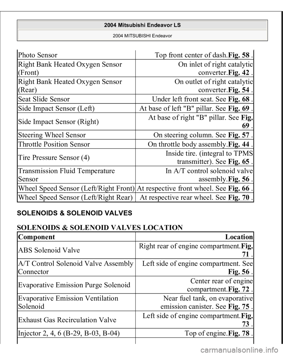
SOLENOIDS & SOLENOID VALVES SOLENOIDS & SOLENOID VALVES LOCATION Photo Sensor
Top front center of dash.Fig. 58
.
Right Bank Heated Oxygen Sensor
(Front)
On inlet of right catalytic
converter.Fig. 42
.
Right Bank Heated Oxygen Sensor
(Rear)
On outlet of right catalytic
converter.Fig. 54
.
Seat Slide Sensor
Under left front seat. See Fig. 68
.
Side Impact Sensor (Left)
At base of left "B" pillar. See Fig. 69
.
Side Impact Sensor (Right)
At base of right "B" pillar. See Fig.
69 .
Steering Wheel Sensor
On steering column. See Fig. 57
.
Throttle Position Sensor
On throttle body assembly.Fig. 44
.
Tire Pressure Sensor (4)
Inside tire. (integral to TPMS
transmitter). See Fig. 65
.
Transmission Fluid Temperature
Sensor
In A/T control solenoid valve
assembly.Fig. 56
.
Wheel Speed Sensor (Left/Right Front)
At respective front wheel. See Fig. 66
.
Wheel Speed Sensor (Left/Right Rear)
At respective rear wheel. See Fig. 70
.
Component
Location
ABS Solenoid Valve
Right rear of engine compartment.Fig.
71 .
A/T Control Solenoid Valve Assembly
Connector
Left side of engine compartment. See
Fig. 56
.
Evaporative Emission Purge Solenoid
Center rear of engine
compartment.Fig. 72
.
Evaporative Emission Ventilation
Solenoid
Near fuel tank, on evaporative
emission canister. See Fig. 75
.
Exhaust Gas Recirculation Valve
Left side of engine compartment.Fig.
73 .
Injector 2, 4, 6 (B-29, B-03, B-04)
Top of engine.Fig. 78
.
2004 Mitsubishi Endeavor LS
2004 MITSUBISHI Endeavor
Page 1812 of 3870
Courtesy of MITSUBISHI MOTOR SALES OF AMERICA
.
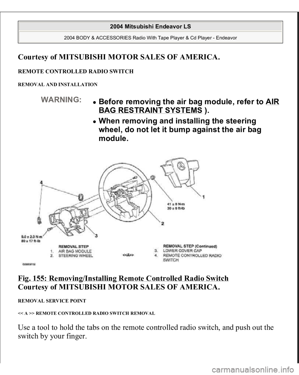
REMOTE CONTROLLED RADIO SWITCH REMOVAL AND INSTALLATION Fig. 155: Removing/Installing Remote Controlled Radio Switch
Courtesy of MITSUBISHI MOTOR SALES OF AMERICA.
REMOVAL SERVICE POINT << A >> REMOTE CONTROLLED RADIO SWITCH REMOVAL Use a tool to hold the tabs on the remote controlled radio switch, and push out the
switch b
y your fin
ger.
WARNING:
Before removing the air bag module, refer to AIR BAG RESTRAINT SYSTEMS
).
When removing and installing the steering
wheel, do not let it bump against the air bag
module.
2004 Mitsubishi Endeavor LS
2004 BODY & ACCESSORIES Radio With Tape Player & Cd Player - Endeavor
Page 1939 of 3870
If the front suspension is faulty, the vehicle will not run straightforward or noise
will occur. Incorrect wheel alignment, malfunction of strut assembly, stabilizer bar,
coil spring, or worn or out-of-balance tires can cause these problems. FRONT SUSPENSION DIAGNOSIS TROUBLESHOOTING STRATEGY Use these steps to plan your diagnostic strategy. If you follow them carefully, you
will be sure that you have exhausted most of the possible ways to find a front
suspension fault.
1. Gather information from the customer.
2. Verify that the condition described by the customer exists.
3. Find and repair the malfunction by following the Symptom Chart and
Symptom Procedures.
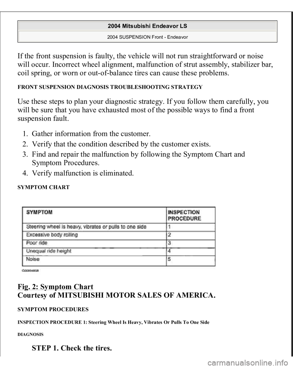
4. Verify malfunction is eliminated. SYMPTOM CHART Fig. 2: Symptom Chart
Courtesy of MITSUBISHI MOTOR SALES OF AMERICA.
SYMPTOM PROCEDURES INSPECTION PROCEDURE 1: Steering Wheel Is Heavy, Vibrates Or Pulls To One Side DIAGNOSIS
STEP 1. Check the tires.
2004 Mitsubishi Endeavor LS 2004 SUSPENSION Front - Endeavor
Page 1945 of 3870
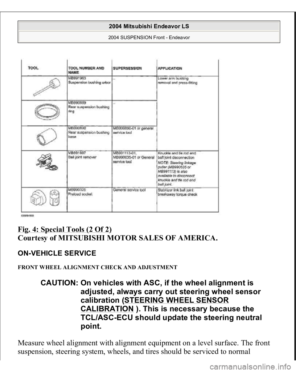
Fig. 4: Special Tools (2 Of 2)
Courtesy of MITSUBISHI MOTOR SALES OF AMERICA.
ON-VEHICLE SERVICE FRONT WHEEL ALIGNMENT CHECK AND ADJUSTMENT Measure wheel alignment with alignment equipment on a level surface. The front
sus
pension, steerin
g system, wheels, and tires should be serviced to normal
CAUTION: On vehicles with ASC, if the wheel alignment is
adjusted, always carry out steering wheel sensor
calibration (STEERING WHEEL SENSOR
CALIBRATION
). This is necessary because the
TCL/ASC-ECU should update the steering neutral
point.
2004 Mitsubishi Endeavor LS 2004 SUSPENSION Front - Endeavor
Page 1947 of 3870
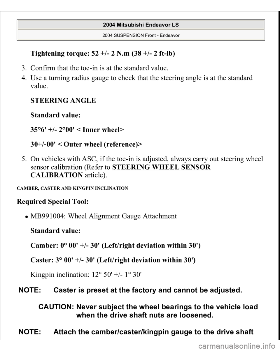
Tightening torque: 52 +/- 2 N.m (38 +
/-2 f
t-lb)
3. Confirm that the toe-in is at the standard value.
4. Use a turning radius gauge to check that the steering angle is at the standard
value.
STEERING ANGLE
Standard value:
35°6' +/- 2°00' < Inner wheel>
30+/-00' < Outer wheel (reference)>
5. On vehicles with ASC, if the toe-in is adjusted, always carry out steering wheel
sensor calibration (Refer to STEERING WHEEL SENSOR
CALIBRATION
article).
CAMBER, CASTER AND KINGPIN INCLINATION Required Special Tool:
MB991004: Wheel Alignment Gauge Attachment
Standard value:
Camber: 0° 00' +/- 30' (Left/right deviation within 30')
Caster: 3° 00' +/- 30' (Left/right deviation within 30')
Kingpin inclination: 12° 50' +/- 1° 30'
NOTE: Caster is preset at the factory and cannot be adjusted.
CAUTION: Never subject the wheel bearings to the vehicle load
when the drive shaft nuts are loosened.
NOTE: Attach the camber/caster/kingpin gauge to the drive shaft
2004 Mitsubishi Endeavor LS 2004 SUSPENSION Front - Endeavor
Page 1985 of 3870
2004 ELECTRICAL
Fuses & Circuit Breakers - Endeavor
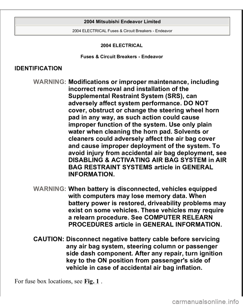
IDENTIFICATION For fuse box locations, see Fig. 1
.
WARNING:Modifications or improper maintenance, including
incorrect removal and installation of the
Supplemental Restraint System (SRS), can
adversely affect system performance. DO NOT
cover, obstruct or change the steering wheel horn
pad in any way, as such action could cause
improper function of the system. Use only plain
water when cleaning the horn pad. Solvents or
cleaners could adversely affect the air bag cover
and cause improper deployment of the system. To
avoid injury from accidental air bag deployment, see
DISABLING & ACTIVATING AIR BAG SYSTEM in AIR
BAG RESTRAINT SYSTEMS article in GENERAL
INFORMATION.
WARNING:When battery is disconnected, vehicles equipped
with computers may lose memory data. When
battery power is restored, driveability problems may
exist on some vehicles. These vehicles may require
a relearn procedure. See COMPUTER RELEARN
PROCEDURES article in GENERAL INFORMATION.
CAUTION: Disconnect negative battery cable before servicing
any air bag system, steering column or passenger
side dash component. After any repair, turn ignition
key to the ON position from passenger's side of
vehicle in case of accidental air bag inflation.
2004 Mitsubishi Endeavor Limited
2004 ELECTRICAL Fuses & Circuit Breakers - Endeavor
2004 Mitsubishi Endeavor Limited
2004 ELECTRICAL Fuses & Circuit Breakers - Endeavor
Page 2378 of 3870
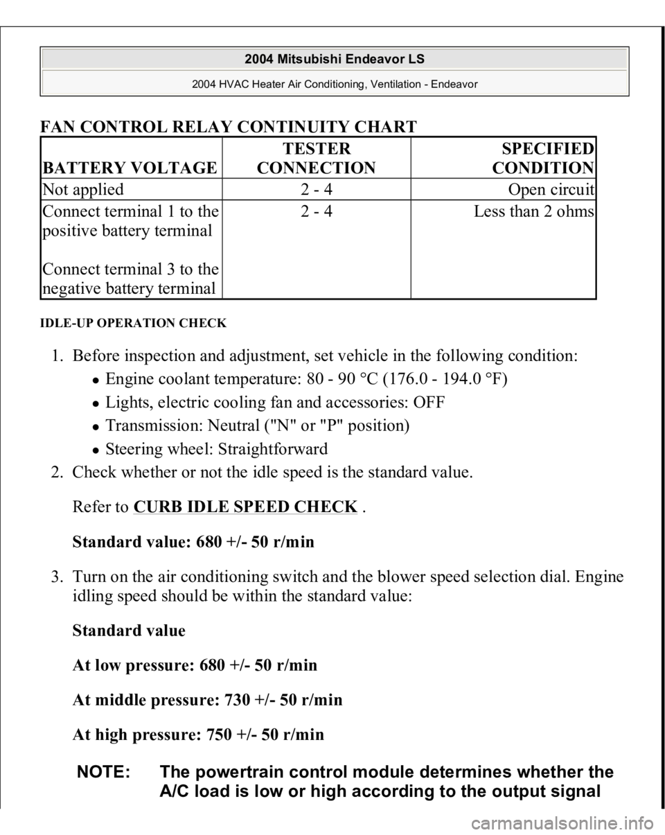
FAN CONTROL RELAY CONTINUITY CHART
IDLE-UP OPERATION CHECK 1. Before inspection and adjustment, set vehicle in the following condition:
Engine coolant temperature: 80 - 90 °C (176.0 - 194.0 °F) Lights, electric cooling fan and accessories: OFF Transmission: Neutral ("N" or "P" position) Steering wheel: Straightforward
2. Check whether or not the idle speed is the standard value.
Refer to
CURB IDLE SPEED CHECK
.
Standard value: 680 +/- 50 r/min
3. Turn on the air conditioning switch and the blower speed selection dial. Engine
idling speed should be within the standard value:
Standard value
At low pressure: 680 +/- 50 r/min
At middle pressure: 730 +/- 50 r/min
At high pressure: 750 +/- 50 r/min
BATTERY VOLTAGE
TESTER
CONNECTION
SPECIFIED
CONDITION
Not applied
2 - 4
Open circuit
Connect terminal 1 to the
positive battery terminal
Connect terminal 3 to the
negative battery terminal
2 - 4
Less than 2 ohms
NOTE: The powertrain control module determines whether the
A/C load is low or high according to the output signal
2004 Mitsubishi Endeavor LS
2004 HVAC Heater Air Conditioning, Ventilation - Endeavor
Page 2668 of 3870
Fig. 118: Identifying TP Lock Check Table
Courtesy of MITSUBISHI MOTOR SALES OF AMERICA.
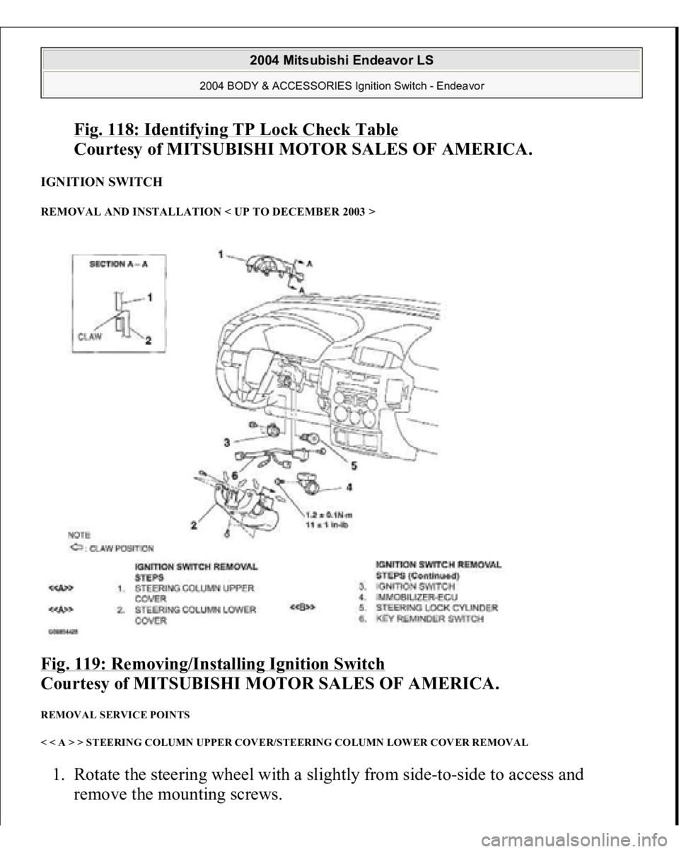
IGNITION SWITCH REMOVAL AND INSTALLATION < UP TO DECEMBER 2003 > Fig. 119: Removing/Installing Ignition Switch
Courtesy of MITSUBISHI MOTOR SALES OF AMERICA.
REMOVAL SERVICE POINTS
< < A > > STEERING COLUMN UPPER COVER/STEERING COLUMN LOWER COVER REMOVAL 1. Rotate the steering wheel with a slightly from side-to-side to access and
remove the mountin
g screws.
2004 Mitsubishi Endeavor LS
2004 BODY & ACCESSORIES Ignition Switch - Endeavor