2004 MITSUBISHI ENDEAVOR light
[x] Cancel search: lightPage 277 of 3870
Such shorts can damage fuses or components and may cause a second
Diagnostic Trouble Code (DTC) to set, making diagnosis of original problem
more difficult. Never use an analog volt/ohm meter or test light in place of a Digital Volt/Ohm
Meter (DVOM). Use only a DVOM with a maximum test current of 2 mA
(milliamps) at minimum range of resistance measurement. If SRS is not fully functional for any reason, DO NOT drive vehicle until
system is repaired and fully functional. DO NOT remove bulbs, modules,
sensors, or other components or in any way disable system from operating
normally. If SRS is not functional, park vehicle until repairs are made.
DISABLING & ACTIVATING AIR BAG SYSTEM To disable system, turn ignition off. Disconnect negative battery cable. Shield cable
end with electrical tape. Wait at least 60 seconds before servicing air bag system.
To activate system, reconnect negative battery cable. Check system operation. See SYSTEM OPERATION CHECK
.
DISPOSAL PROCEDURES DEPLOYED AIR BAG OR SEAT BELT PRETENSIONER Place deployed component in a strong plastic bag and seal tightly. Dispose of
component as you would any other part. No other special disposal procedure is
required. UNDEPLOYED AIR BAG OR SEAT BELT PRETENSIONER
WARNING:Accidental air bag deployment is possible. Personal
injury may result. Read and follow all WARNINGS
and AIR BAG SAFETY PRECAUTIONS
before
working on air bag system or related components.
NOTE: Undeployed air bag modules must be deployed before
disposal. Disposing of an undeployed air bag may violate
federal, state and/or local laws. This also applies to vehicles
that are to be scrapped.
2004 Mitsubishi Endeavor Limited
2004 ACCESSORIES/SAFETY EQUIPMENT Mitsubishi - Air Bag Restraint Systems
Page 287 of 3870
CONSOLE ASSEMBL
Y . Remove left and right A-pillar trim panels.
Remove hood lock release handle.
3. Remove end panel. See Fig. 8
. Remove driver-side knee bolster. Remove fog
light switch. Remove steering column upper and lower covers. Remove
combination meter assembly. Remove center panel assembly. Remove air
vents. Remove radio panel. Remove AC-heater control assembly.
4. Remove hazard warning switch. Remove console meter hood. Remove multi-
center display unit. Remove audio components. Remove glove box assembly.
Remove left and right speaker covers. Remove speakers. Disconnect
clockspring and steering column switch connectors. Remove photo sensor and
photo sensor clamp.
5. Remove interior temperature sensor. Disconnect passenger-side air bag module
connector. Remove left and right center instrument panel brackets. Disconnect
remaining electrical connectors. Remove instrument panel nuts and bolts.
Remove instrument panel.
6. To install, reverse removal procedure. Tighten NEW steering wheel nut and
drive
r-side air ba
g module bolts to s
pecification. Activate air ba
g system.
2004 Mitsubishi Endeavor Limited
2004 ACCESSORIES/SAFETY EQUIPMENT Mitsubishi - Air Bag Restraint Systems
Page 299 of 3870
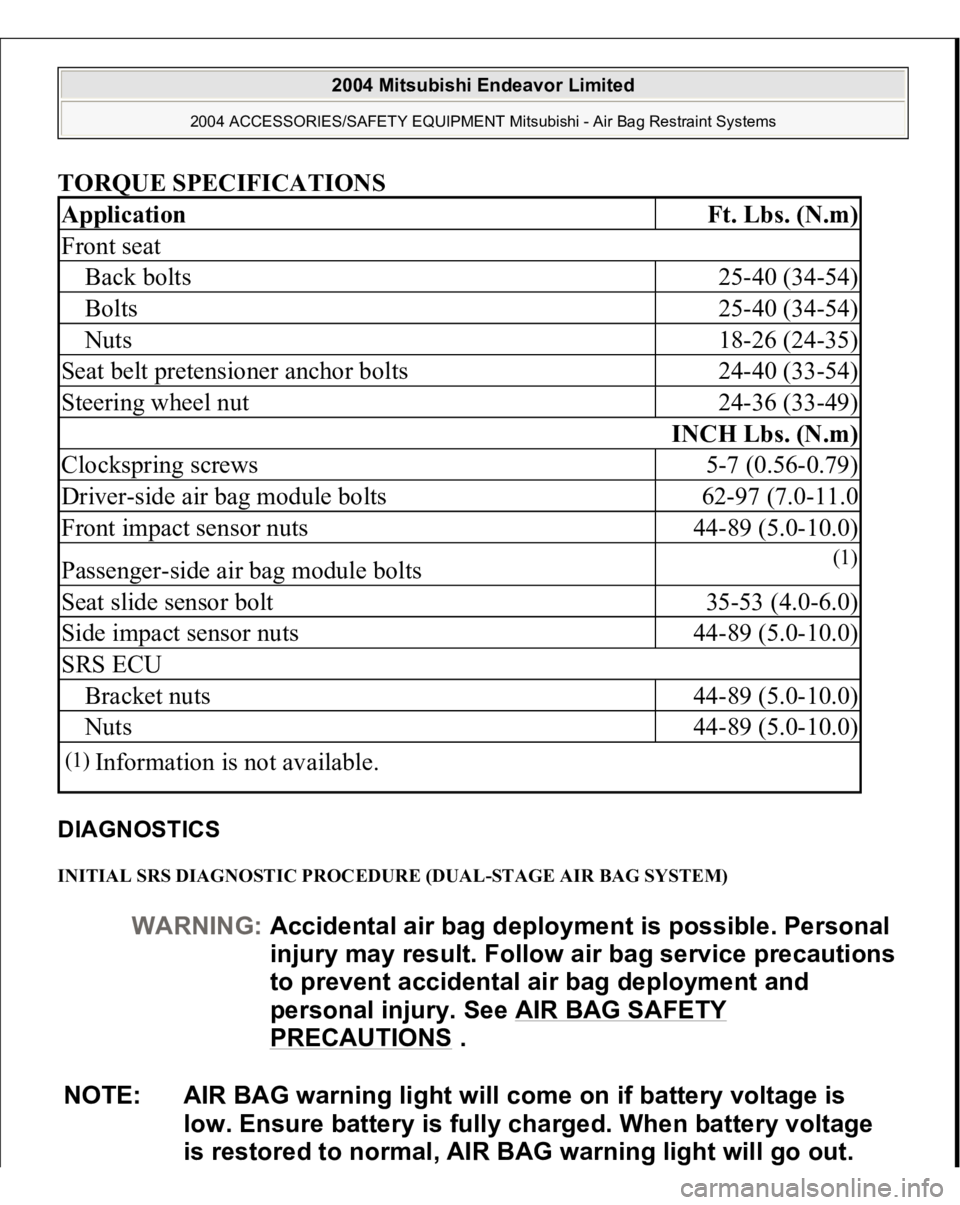
TORQUE SPECIFICATIONS DIAGNOSTICS INITIAL SRS DIAGNOSTIC PROCEDURE (DUAL-STAGE AIR BAG SYSTEM) Application
Ft. Lbs. (N.m)
Front seatBack bolts
25-40 (34-54)
Bolts
25-40 (34-54)
Nuts
18-26 (24-35)
Seat belt pretensioner anchor bolts
24-40 (33-54)
Steering wheel nut
24-36 (33-49)
INCH Lbs. (N.m)
Clockspring screws
5-7 (0.56-0.79)
Driver-side air bag module bolts
62-97 (7.0-11.0
Front impact sensor nuts
44-89 (5.0-10.0)
Passenger-side air bag module bolts
(1)
Seat slide sensor bolt
35-53 (4.0-6.0)
Side impact sensor nuts
44-89 (5.0-10.0)
SRS ECUBracket nuts
44-89 (5.0-10.0)
Nuts
44-89 (5.0-10.0)
(1)
Information is not available.
WARNING:Accidental air bag deployment is possible. Personal
in
jury ma
y result. Follow air ba
g service precautions
to prevent accidental air bag deployment and
personal injury. See AIR BAG SAFETY
PRECAUTIONS
.
NOTE: AIR BAG warning light will come on if battery voltage is
low. Ensure battery is fully charged. When battery voltage
is restored to normal, AIR BAG warning light will go out.
2004 Mitsubishi Endeavor Limited
2004 ACCESSORIES/SAFETY EQUIPMENT Mitsubishi - Air Bag Restraint Systems
Page 300 of 3870
1. Turn ignition on. If AIR BAG warning light comes on for 7 seconds and then
goes off, SRS is functioning properly. If AIR BAG warning light does not
function as described, turn ignition off. If AIR BAG warning light malfunction
or scan tool communication problems are encountered, diagnose malfunction
using appropriate table. SeeSCAN TOOL COMMUNICATION
SYMPTOMS (SINGLE
-STAGE AIR BAG SYSTEMS)
and SCAN TOOL
COMMUNICATION SYMPTOMS (DUAL
-STAGE AIR BAG
SYSTEMS)
tables.
2. Utilizing a laptop computer, check for Diagnostic Trouble Codes (DTCs) by
connecting Scan Tool (MB991958) to Data Link Connector (DLC), located
under left side of instrument panel, using Vehicle Communication Interface
(MB991824), USB Cable (MB991827) and Main Harness (MB991911). See
Fig. 18
. Turn ignition on and follow instructions provided with scan tool.
Diagnose displayed DTCs for appropriate air bag system. See SCAN TOOL
COMMUNICATION SYMPTOMS (SINGLE
-STAGE AIR BAG
SYSTEMS)
and SCAN TOOL COMMUNICATION SYMPTOMS
(DUAL
-STAGE AIR BAG SYSTEMS)
. When diagnosis and repairs are
com
plete, erase DTCs.
2004 Mitsubishi Endeavor Limited
2004 ACCESSORIES/SAFETY EQUIPMENT Mitsubishi - Air Bag Restraint Systems
Page 302 of 3870
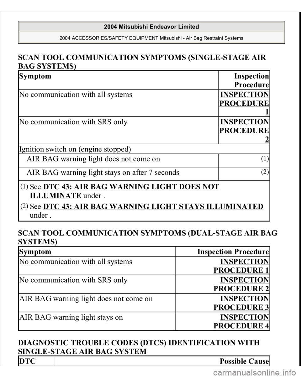
SCAN TOOL COMMUNICATION SYMPTOMS (SINGLE-STAGE AI
R
BAG SYSTEMS)
SCAN TOOL COMMUNICATION SYMPTOMS (DUAL-STAGE AIR BAG
SYSTEMS)
DIAGNOSTIC TROUBLE CODES (DTCS) IDENTIFICATION WITH
SINGLE-STAGE AIR BAG SYSTEM
Symptom
Ins
pection
Procedure
No communication with all systems
INSPECTION PROCEDURE
1
No communication with SRS only
INSPECTION PROCEDURE
2
Ignition switch on (engine stopped)AIR BAG warning light does not come on
(1)
AIR BAG warning light stays on after 7 seconds
(2)
(1)
See DTC 43: AIR BAG WARNING LIGHT DOES NOT ILLUMINATE
under .
(2)
See DTC 43: AIR BAG WARNING LIGHT STAYS ILLUMINATED
under .
Symptom
Inspection Procedure
No communication with all systems
INSPECTION PROCEDURE 1
No communication with SRS only
INSPECTION PROCEDURE 2
AIR BAG warning light does not come on
INSPECTION PROCEDURE 3
AIR BAG warning light stays on
INSPECTION PROCEDURE 4
DTC
Possible Cause
2004 Mitsubishi Endeavor Limited
2004 ACCESSORIES/SAFETY EQUIPMENT Mitsubishi - Air Bag Restraint Systems
Page 303 of 3870
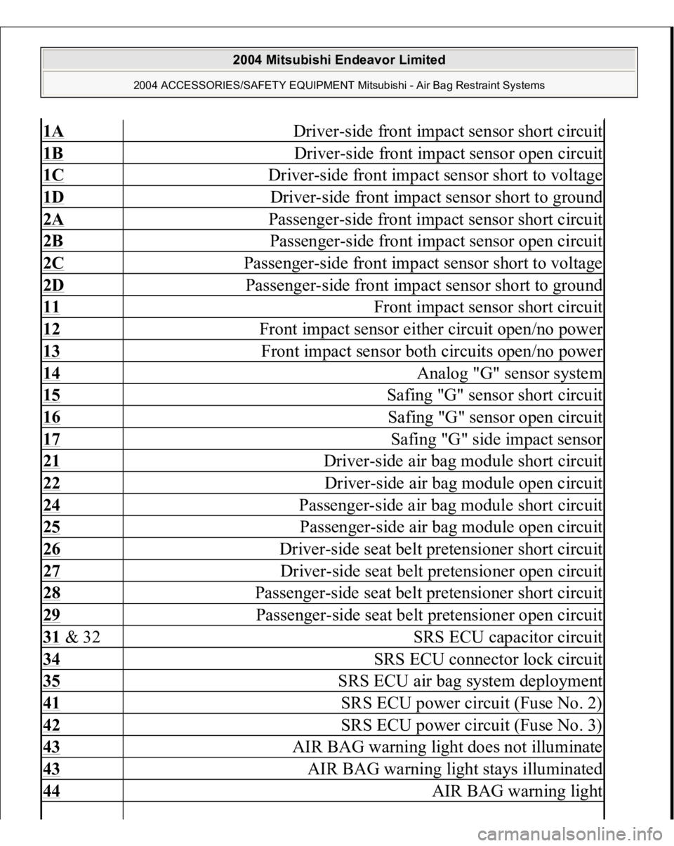
1A
Driver-side front impact sensor short circuit
1B
Driver-side front impact sensor open circuit
1C
Driver-side front impact sensor short to voltage
1D
Driver-side front impact sensor short to ground
2A
Passenger-side front impact sensor short circuit
2B
Passenger-side front impact sensor open circuit
2C
Passenger-side front impact sensor short to voltage
2D
Passenger-side front impact sensor short to ground
11
Front impact sensor short circuit
12
Front impact sensor either circuit open/no power
13
Front impact sensor both circuits open/no power
14
Analog "G" sensor system
15
Safing "G" sensor short circuit
16
Safing "G" sensor open circuit
17
Safing "G" side impact sensor
21
Driver-side air bag module short circuit
22
Driver-side air bag module open circuit
24
Passenger-side air bag module short circuit
25
Passenger-side air bag module open circuit
26
Driver-side seat belt pretensioner short circuit
27
Driver-side seat belt pretensioner open circuit
28
Passenger-side seat belt pretensioner short circuit
29
Passenger-side seat belt pretensioner open circuit
31 & 32
SRS ECU capacitor circuit
34
SRS ECU connector lock circuit
35
SRS ECU air bag system deployment
41
SRS ECU power circuit (Fuse No. 2)
42
SRS ECU power circuit (Fuse No. 3)
43
AIR BAG warning light does not illuminate
43
AIR BAG warning light stays illuminated
44
AIR BAG warning light
2004 Mitsubishi Endeavor Limited
2004 ACCESSORIES/SAFETY EQUIPMENT Mitsubishi - Air Bag Restraint Systems
Page 307 of 3870
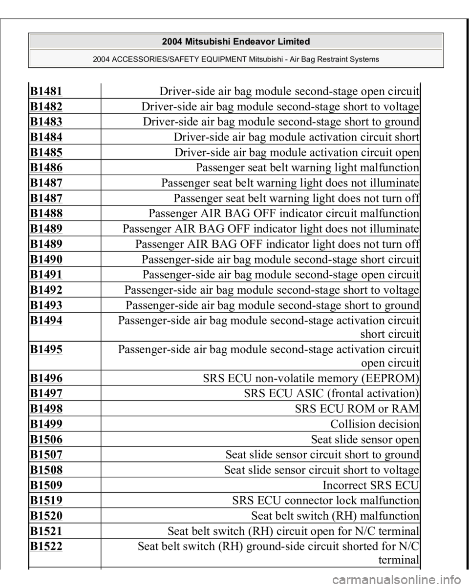
B1481
Driver-side air bag module second-stage open circuit
B1482
Driver-side air bag module second-stage short to voltage
B1483
Driver-side air bag module second-stage short to ground
B1484
Driver-side air bag module activation circuit short
B1485
Driver-side air bag module activation circuit open
B1486
Passenger seat belt warning light malfunction
B1487
Passenger seat belt warning light does not illuminate
B1487
Passenger seat belt warning light does not turn of
f
B1488
Passenger AIR BAG OFF indicator circuit malfunction
B1489
Passenger AIR BAG OFF indicator light does not illuminate
B1489
Passenger AIR BAG OFF indicator light does not turn of
f
B1490
Passenger-side air bag module second-stage short circuit
B1491
Passenger-side air bag module second-stage open circuit
B1492
Passenger-side air bag module second-stage short to voltage
B1493
Passenger-side air bag module second-stage short to ground
B1494
Passenger-side air bag module second-stage activation circuit
short circuit
B1495
Passenger-side air bag module second-stage activation circuit
open circuit
B1496
SRS ECU non-volatile memory (EEPROM)
B1497
SRS ECU ASIC (frontal activation)
B1498
SRS ECU ROM or RAM
B1499
Collision decision
B1506
Seat slide sensor open
B1507
Seat slide sensor circuit short to ground
B1508
Seat slide sensor circuit short to voltage
B1509
Incorrect SRS ECU
B1519
SRS ECU connector lock malfunction
B1520
Seat belt switch (RH) malfunction
B1521
Seat belt switch (RH) circuit open for N/C terminal
B1522
Seat belt switch (RH) ground-side circuit shorted for N/C
terminal
2004 Mitsubishi Endeavor Limited
2004 ACCESSORIES/SAFETY EQUIPMENT Mitsubishi - Air Bag Restraint Systems
Page 329 of 3870
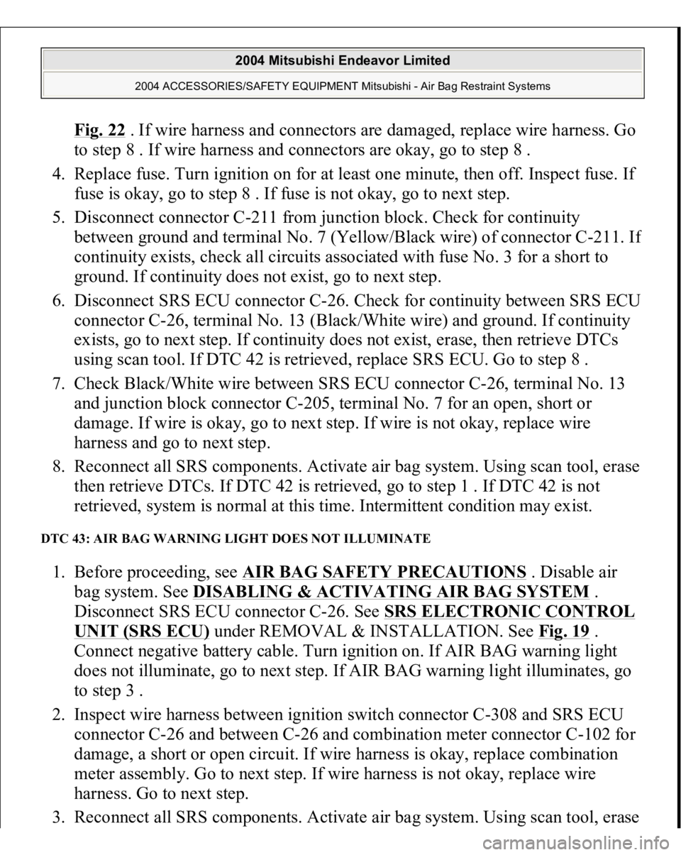
Fig. 22
. If wire harness and connectors are damaged, replace wire harness. Go
to step 8 . If wire harness and connectors are okay, go to step 8 .
4. Replace fuse. Turn ignition on for at least one minute, then off. Inspect fuse. If
fuse is okay, go to step 8 . If fuse is not okay, go to next step.
5. Disconnect connector C-211 from junction block. Check for continuity
between ground and terminal No. 7 (Yellow/Black wire) of connector C-211. I
f
continuity exists, check all circuits associated with fuse No. 3 for a short to
ground. If continuity does not exist, go to next step.
6. Disconnect SRS ECU connector C-26. Check for continuity between SRS ECU
connector C-26, terminal No. 13 (Black/White wire) and ground. If continuity
exists, go to next step. If continuity does not exist, erase, then retrieve DTCs
using scan tool. If DTC 42 is retrieved, replace SRS ECU. Go to step 8 .
7. Check Black/White wire between SRS ECU connector C-26, terminal No. 13
and junction block connector C-205, terminal No. 7 for an open, short or
damage. If wire is okay, go to next step. If wire is not okay, replace wire
harness and go to next step.
8. Reconnect all SRS components. Activate air bag system. Using scan tool, erase
then retrieve DTCs. If DTC 42 is retrieved, go to step 1 . If DTC 42 is not
retrieved, system is normal at this time. Intermittent condition may exist.
DTC 43: AIR BAG WARNING LIGHT DOES NOT ILLUMINATE 1. Before proceeding, see AIR BAG SAFETY PRECAUTIONS
. Disable air
bag system. See DISABLING & ACTIVATING AIR BAG SYSTEM
.
Disconnect SRS ECU connector C-26. See SRS ELECTRONIC CONTROL
UNIT (SRS ECU)
under REMOVAL & INSTALLATION. See Fig. 19
.
Connect negative battery cable. Turn ignition on. If AIR BAG warning light
does not illuminate, go to next step. If AIR BAG warning light illuminates, go
to step 3 .
2. Inspect wire harness between ignition switch connector C-308 and SRS ECU
connector C-26 and between C-26 and combination meter connector C-102 for
damage, a short or open circuit. If wire harness is okay, replace combination
meter assembly. Go to next step. If wire harness is not okay, replace wire
harness. Go to next step.
3. Reconnect all SRS com
ponents. Activate air ba
g system. Usin
g scan tool, erase
2004 Mitsubishi Endeavor Limited
2004 ACCESSORIES/SAFETY EQUIPMENT Mitsubishi - Air Bag Restraint Systems