Page 1279 of 3870
MB991824: V.C.I. MB991827: MUT-III USB Cable. MB991910: MUT-III Main Harness A. MB991519: Generator Harness Connector.
This test determines whether the voltage regulator is correctly controlling the
generator output voltage. See Fig. 5
.
Fig. 5: Regulated Voltage Test
Courtesy of MITSUBISHI MOTOR SALES OF AMERICA.
1. Always be sure to check the following before the test:
WARNING:Battery posts, terminals and related accessories
contain lead and lead compounds. Wash hands
after handling.
2004 Mitsubishi Endeavor Limited
2004 STARTING & CHARGING SYSTEMS Generators & Regulators - Endeavor
Page 1280 of 3870

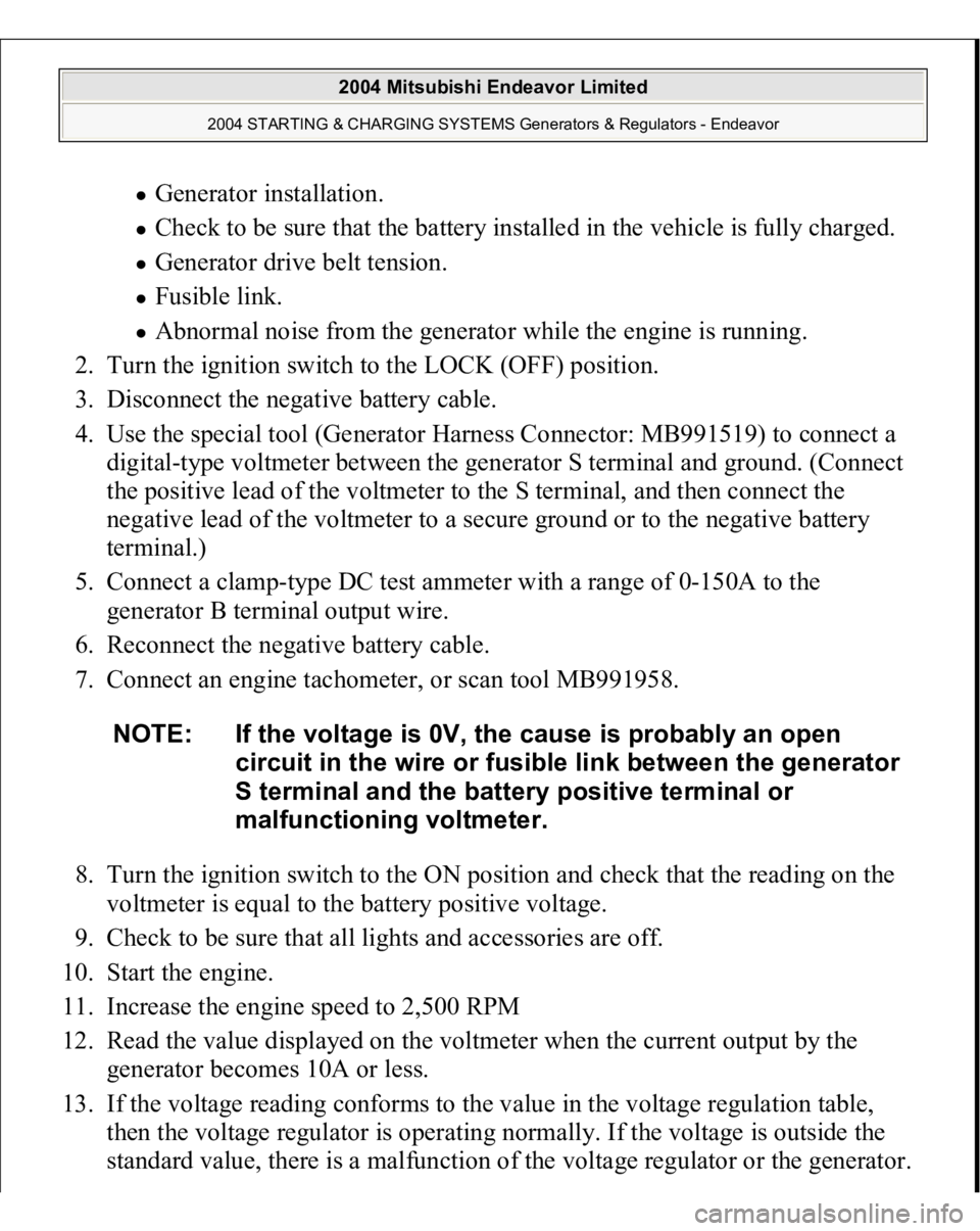
Generator installation. Check to be sure that the battery installed in the vehicle is fully charged. Generator drive belt tension. Fusible link. Abnormal noise from the generator while the engine is running.
2. Turn the ignition switch to the LOCK (OFF) position.
3. Disconnect the negative battery cable.
4. Use the special tool (Generator Harness Connector: MB991519) to connect a
digital-type voltmeter between the generator S terminal and ground. (Connect
the positive lead of the voltmeter to the S terminal, and then connect the
negative lead of the voltmeter to a secure ground or to the negative battery
terminal.)
5. Connect a clamp-type DC test ammeter with a range of 0-150A to the
generator B terminal output wire.
6. Reconnect the negative battery cable.
7. Connect an engine tachometer, or scan tool MB991958.
8. Turn the ignition switch to the ON position and check that the reading on the
voltmeter is equal to the battery positive voltage.
9. Check to be sure that all lights and accessories are off.
10. Start the engine.
11. Increase the engine speed to 2,500 RPM
12. Read the value displayed on the voltmeter when the current output by the
generator becomes 10A or less.
13. If the voltage reading conforms to the value in the voltage regulation table,
then the voltage regulator is operating normally. If the voltage is outside the
standard value, there is a malfunction of the volta
ge re
gulator or the
generator.
NOTE: If the voltage is 0V, the cause is probably an open
circuit in the wire or fusible link between the generator
S terminal and the battery positive terminal or
malfunctioning voltmeter.
2004 Mitsubishi Endeavor Limited
2004 STARTING & CHARGING SYSTEMS Generators & Regulators - Endeavor
Page 1281 of 3870

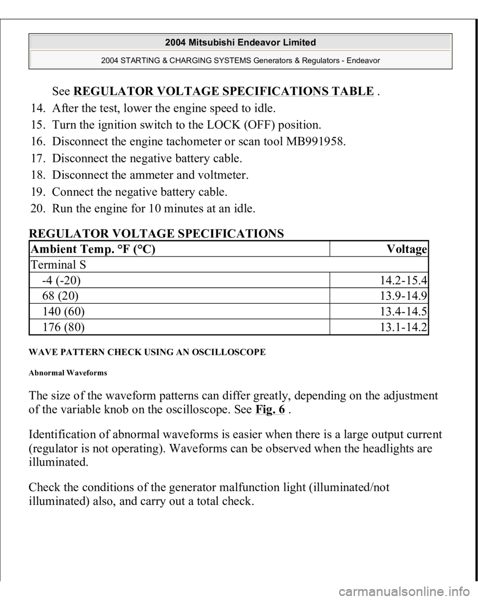
See REGULATOR VOLTAGE SPECIFICATIONS TABLE
.
14. After the test, lower the engine speed to idle.
15. Turn the ignition switch to the LOCK (OFF) position.
16. Disconnect the engine tachometer or scan tool MB991958.
17. Disconnect the negative battery cable.
18. Disconnect the ammeter and voltmeter.
19. Connect the negative battery cable.
20. Run the engine for 10 minutes at an idle.
REGULATOR VOLTAGE SPECIFICATIONS
WAVE PATTERN CHECK USING AN OSCILLOSCOPE Abnormal Waveforms The size of the waveform patterns can differ greatly, depending on the adjustment
of the variable knob on the oscilloscope. See Fig. 6
.
Identification of abnormal waveforms is easier when there is a large output current
(regulator is not operating). Waveforms can be observed when the headlights are
illuminated.
Check the conditions of the generator malfunction light (illuminated/not
illuminated
) also, and carr
y out a total check.
Ambient Temp. °F (°C)
Voltage
Terminal S-4 (-20)
14.2-15.4
68 (20)
13.9-14.9
140 (60)
13.4-14.5
176 (80)
13.1-14.2
2004 Mitsubishi Endeavor Limited
2004 STARTING & CHARGING SYSTEMS Generators & Regulators - Endeavor
Page 2378 of 3870

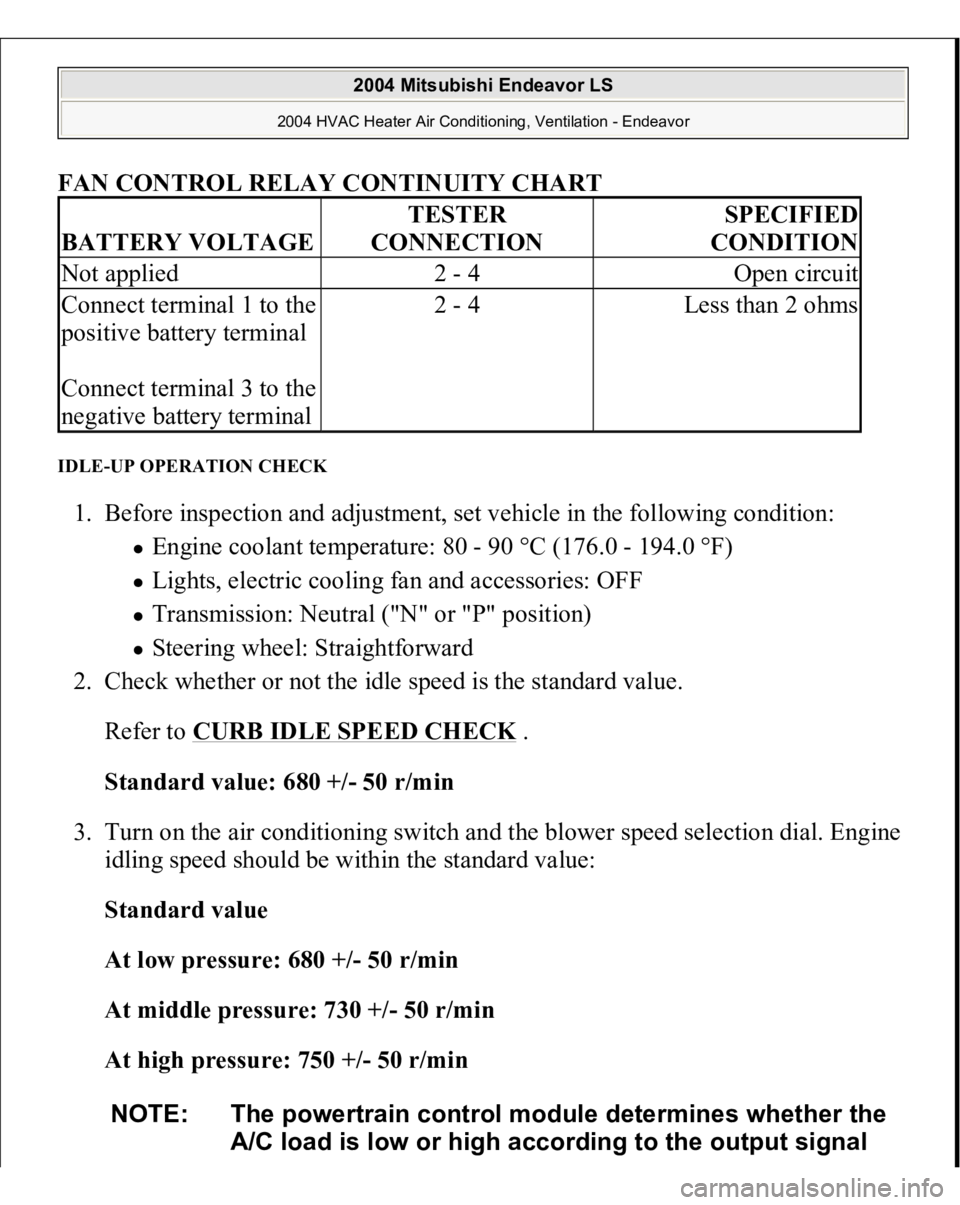
FAN CONTROL RELAY CONTINUITY CHART
IDLE-UP OPERATION CHECK 1. Before inspection and adjustment, set vehicle in the following condition:
Engine coolant temperature: 80 - 90 °C (176.0 - 194.0 °F) Lights, electric cooling fan and accessories: OFF Transmission: Neutral ("N" or "P" position) Steering wheel: Straightforward
2. Check whether or not the idle speed is the standard value.
Refer to
CURB IDLE SPEED CHECK
.
Standard value: 680 +/- 50 r/min
3. Turn on the air conditioning switch and the blower speed selection dial. Engine
idling speed should be within the standard value:
Standard value
At low pressure: 680 +/- 50 r/min
At middle pressure: 730 +/- 50 r/min
At high pressure: 750 +/- 50 r/min
BATTERY VOLTAGE
TESTER
CONNECTION
SPECIFIED
CONDITION
Not applied
2 - 4
Open circuit
Connect terminal 1 to the
positive battery terminal
Connect terminal 3 to the
negative battery terminal
2 - 4
Less than 2 ohms
NOTE: The powertrain control module determines whether the
A/C load is low or high according to the output signal
2004 Mitsubishi Endeavor LS
2004 HVAC Heater Air Conditioning, Ventilation - Endeavor
Page 3339 of 3870

2. Turn the ignition switch to the "ON" position.
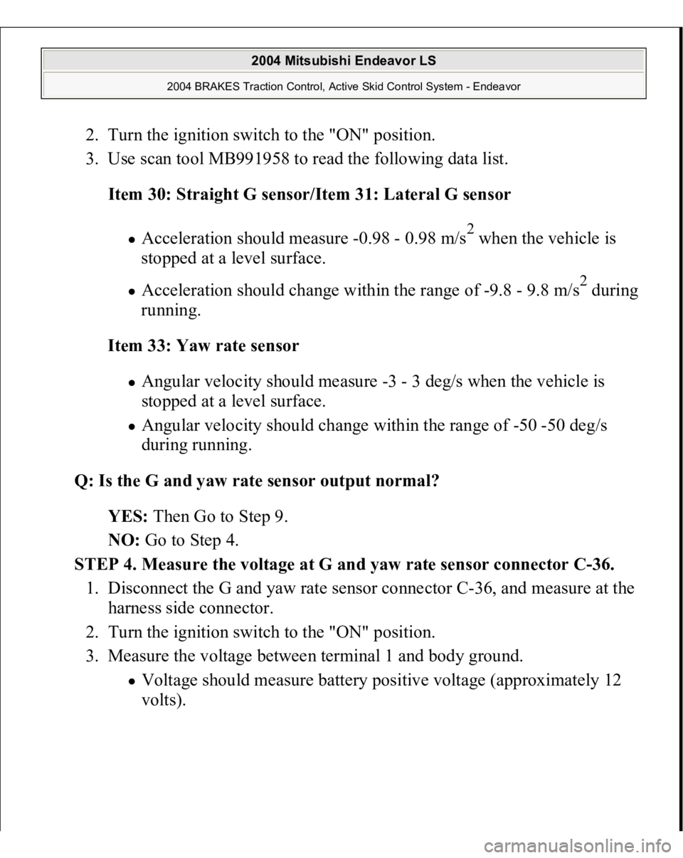
3. Use scan tool MB991958 to read the following data list.
Item 30: Straight G sensor/Item 31: Lateral G sensor
Acceleration should measure -0.98 - 0.98 m/s
2 when the vehicle is
stopped at a level surface.
Acceleration should change within the range of -9.8 - 9.8 m/s
2 during
running.
Item 33: Yaw rate sensor
Angular velocity should measure -3 - 3 deg/s when the vehicle is
stopped at a level surface. Angular velocity should change within the range of -50 -50 deg/s
during running.
Q: Is the G and yaw rate sensor output normal?
YES: Then Go to Step 9.
NO: Go to Step 4.
STEP 4. Measure the voltage at G and yaw rate sensor connector C-36.
1. Disconnect the G and yaw rate sensor connector C-36, and measure at the
harness side connector.
2. Turn the ignition switch to the "ON" position.
3. Measure the voltage between terminal 1 and body ground. Voltage should measure battery positive voltage (approximately 12
volts
).
2004 Mitsubishi Endeavor LS
2004 BRAKES Traction Control, Active Skid Control System - Endeavor