Page 1245 of 3870
11. After repeatedly revving the engine up to 3,000 r/min several times, stop the
engine.
12. Remove the radiator cap after the engine has cooled, and pour in coolant up to
the brim. Reinstall the cap.
13. Add coolant to the radiator condenser tank assembly between the "FULL" and
"LOW" mark if necessary. ENGINE COOLANT CONCENTRATION TEST Refer to RECOMMENDED LUBRICANTS AND LUBRICANT CAPACITIES
.
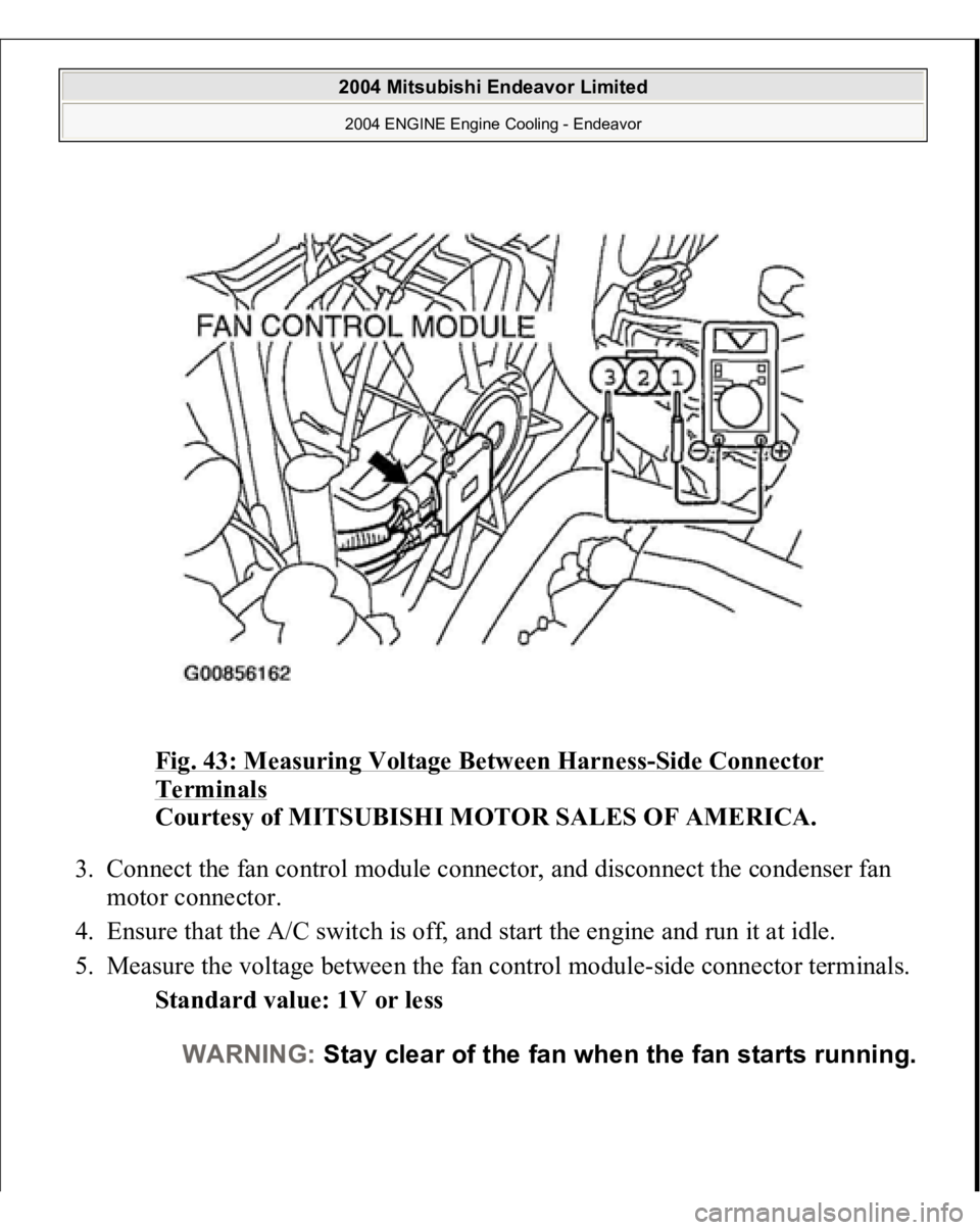
FAN CONTROL MODULE CHECK 1. Remove the fan control module connector.
2. Turn the ignition switch to the "ON" position, and measure the voltage
between the harness-side connector terminals.
Standard value: Battery positive voltage
CAUTION: Do not overfill the radiator condenser tank
assembly.
2004 Mitsubishi Endeavor Limited 2004 ENGINE Engine Cooling - Endeavor
Page 1246 of 3870
Fig. 43: Measuring Voltage Between Harness
-Side Connector
Terminals
Courtesy of MITSUBISHI MOTOR SALES OF AMERICA.
3. Connect the fan control module connector, and disconnect the condenser fan
motor connector.
4. Ensure that the A/C switch is off, and start the engine and run it at idle.
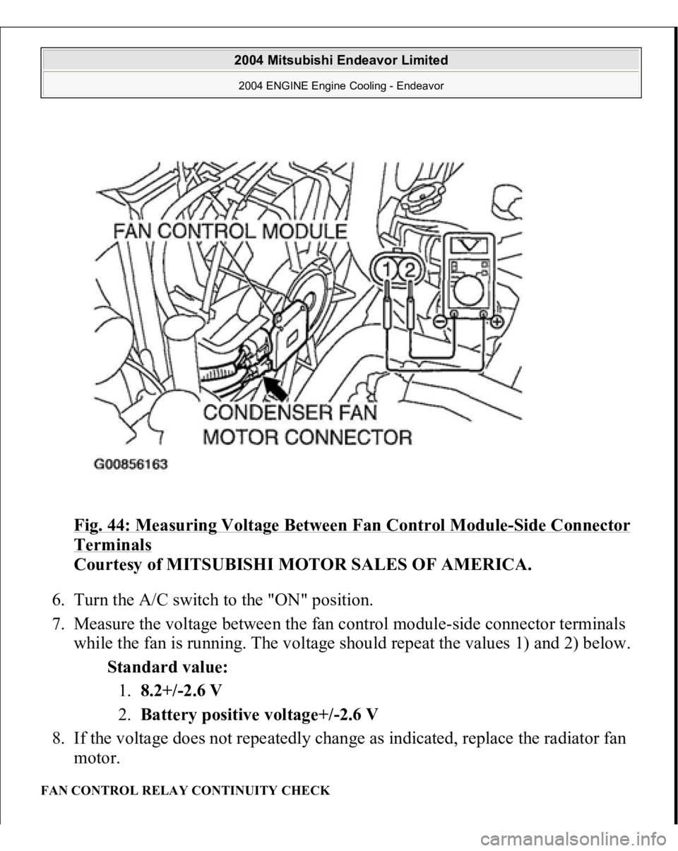
5. Measure the voltage between the fan control module-side connector terminals.
Standard value: 1V or less
WARNING:Stay clear of the fan when the fan starts running.
2004 Mitsubishi Endeavor Limited 2004 ENGINE Engine Cooling - Endeavor
Page 1247 of 3870
Fig. 44: Measuring Voltage Between Fan Control Module
-Side Connector
Terminals
Courtesy of MITSUBISHI MOTOR SALES OF AMERICA.
6. Turn the A/C switch to the "ON" position.
7. Measure the voltage between the fan control module-side connector terminals
while the fan is running. The voltage should repeat the values 1) and 2) below.
Standard value:
1.8.2+/-2.6 V
2.Battery positive voltage+/-2.6 V
8. If the voltage does not repeatedly change as indicated, replace the radiator fan
motor.
FAN CONTROL RELAY CONTINUITY CHECK
2004 Mitsubishi Endeavor Limited 2004 ENGINE Engine Cooling - Endeavor
Page 1525 of 3870
MB991958: Scan Tool (MUT-III Sub Assembly)
MB991824: V.C.I. MB991827: MUT-III USB Cable MB991910: MUT-III Main Harness A
1. Before checks set the vehicle in the following condition:
Engine coolant temperature: 80 - 95°C (176 - 203°F) Lights and all accessories: OFF Transaxle: P range
2. Remove all of the ignition coils and spark plugs.
3. Disconnect the crankshaft position sensor connector.
NOTE: Vehicles for Canada, the headlight, taillight, etc. remain
lit even when the lighting switch is in "OFF" position
but this is no problem for checks.
NOTE: Doing this will prevent the engine control module from
carrying out ignition and fuel injection.
2004 Mitsubishi Endeavor Limited
2004 ENGINE Engine - Endeavor
Page 1664 of 3870
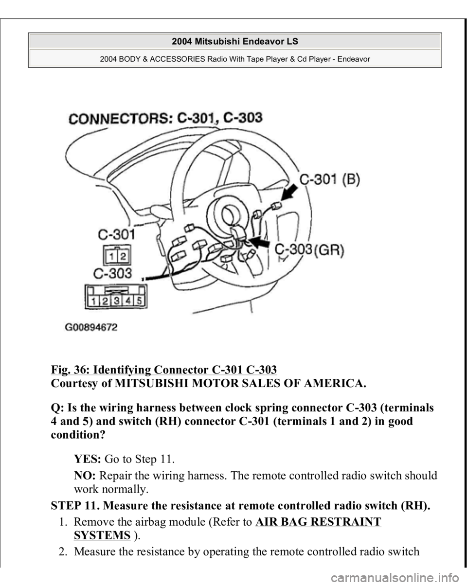
Fig. 36: Identifying Connector C
-301 C
-303
Courtesy of MITSUBISHI MOTOR SALES OF AMERICA.
Q: Is the wiring harness between clock spring connector C-303 (terminals
4 and 5) and switch (RH) connector C-301 (terminals 1 and 2) in good
condition?
YES: Go to Step 11.
NO: Repair the wiring harness. The remote controlled radio switch should
work normally.
STEP 11. Measure the resistance at remote controlled radio switch (RH).
1. Remove the airbag module (Refer to AIR BAG RESTRAINT
SYSTEMS
).
2. Measure the resistance b
y operatin
g the remote controlled radio switch
2004 Mitsubishi Endeavor LS
2004 BODY & ACCESSORIES Radio With Tape Player & Cd Player - Endeavor
Page 1667 of 3870
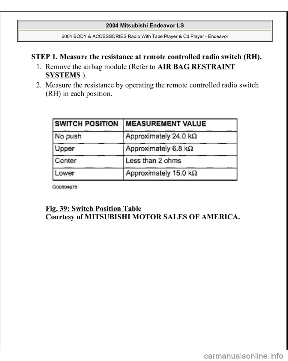
STEP 1. Measure the resistance at remote controlled radio switch (RH).
1. Remove the airbag module (Refer to AIR BAG RESTRAINT
SYSTEMS
).
2. Measure the resistance by operating the remote controlled radio switch
(RH) in each position.
Fig. 39: Switch Position Table
Courtesy of MITSUBISHI MOTOR SALES OF AMERICA.
2004 Mitsubishi Endeavor LS
2004 BODY & ACCESSORIES Radio With Tape Player & Cd Player - Endeavor
Page 1671 of 3870
TECHNICAL DESCRIPTION (COMMENT
)
Refer to INSPECTION PROCEDURE 2
.
TROUBLESHOOTING HINTS Refer to INSPECTION PROCEDURE 2
.
DIAGNOSIS Required Special Tool:
MB991223: Harness set
STEP 1. Measure the resistance at remote controlled radio switch (LH).
1. Remove the airbag module (Refer to AIR BAG RESTRAINT
SYSTEMS
).
2. Measure the resistance by operating the remote controlled radio switch
(LH
) in each
position.
2004 Mitsubishi Endeavor LS
2004 BODY & ACCESSORIES Radio With Tape Player & Cd Player - Endeavor
Page 1812 of 3870
Courtesy of MITSUBISHI MOTOR SALES OF AMERICA
.
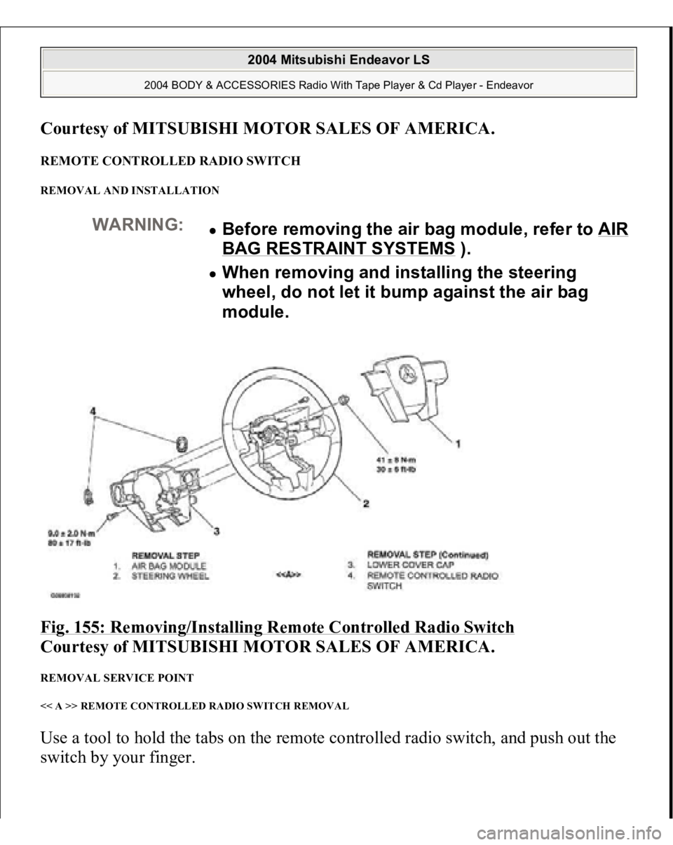
REMOTE CONTROLLED RADIO SWITCH REMOVAL AND INSTALLATION Fig. 155: Removing/Installing Remote Controlled Radio Switch
Courtesy of MITSUBISHI MOTOR SALES OF AMERICA.
REMOVAL SERVICE POINT << A >> REMOTE CONTROLLED RADIO SWITCH REMOVAL Use a tool to hold the tabs on the remote controlled radio switch, and push out the
switch b
y your fin
ger.
WARNING:
Before removing the air bag module, refer to AIR BAG RESTRAINT SYSTEMS
).
When removing and installing the steering
wheel, do not let it bump against the air bag
module.
2004 Mitsubishi Endeavor LS
2004 BODY & ACCESSORIES Radio With Tape Player & Cd Player - Endeavor