Page 2483 of 3870
Fig. 48: Identifying Connectors C
-20 And C
-24
Courtesy of MITSUBISHI MOTOR SALES OF AMERICA.
2. When battery voltage is applied between the terminals 1 and 3, check that
the motor operates. Also, check that there is no abnormal noise.
Q: Is the check result satisfactory?
YES:
Replace the rear blower relay. The rear blower motor should operate
normally.
NO:
Go to Ste
p 14.
2004 Mitsubishi Endeavor LS
2004 HVAC Automatic Air Conditioning - Endeavor
Page 2488 of 3870
YES:
Go to Step 16.
NO:
Replace the rear blower relay. The rear blower motor should operate
normally.
STEP 16. Measure the resistance at floor console rear A/C switch
assembly connector C-19 in order to the ground circuit to the rear blower
motor.
1. Disconnect floor console rear A/C switch assembly connector C-19, and
measure the voltage at the wiring harness side. Fig. 53: Locating Connector C
-19
Courtesy of MITSUBISHI MOTOR SALES OF AMERICA.
2. Measure the resistance value between terminal 3 and ground.
The measured value should be 2 ohms or less.
2004 Mitsubishi Endeavor LS
2004 HVAC Automatic Air Conditioning - Endeavor
Page 2506 of 3870
Fig. 68: Identifying Special Tools
Courtesy of MITSUBISHI MOTOR SALES OF AMERICA.
ON-VEHICLE SERVICE POWER RELAY CHECK REAR BLOWER RELAY CONTINUITY CHECK
2004 Mitsubishi Endeavor LS
2004 HVAC Automatic Air Conditioning - Endeavor
Page 2507 of 3870
Fig. 69: Identifying Power Relay Check
Courtesy of MITSUBISHI MOTOR SALES OF AMERICA.
2004 Mitsubishi Endeavor LS
2004 HVAC Automatic Air Conditioning - Endeavor
Page 2508 of 3870
REAR BLOWER RELAY CONTINUITY CHEC
K
REAR BLOWER UNIT REMOVAL AND INSTALLATION Fig. 70: Removing And Installing Rear Blower Unit
Courtesy of MITSUBISHI MOTOR SALES OF AMERICA.
BATTERY VOLTAGE
TESTER
CONNECTION
SPECIFIED
CONDITION
Not applied
1 - 4
Open circuit
Connect terminal 3 to the
positive battery terminal
Connect terminal 2 to the
negative battery terminal
1 - 4
Less than 2 ohms
2004 Mitsubishi Endeavor LS
2004 HVAC Automatic Air Conditioning - Endeavor
Page 2509 of 3870
INSPECTION RESISTER CHECK Use an ohmmeter to measure the resistance between the terminals. Check that the
measured resistance is at the standard value.
Standard value:
REAR BLOWER RELAY CONTINUITY CHECK
Fig. 71: Identifying Standard ValueMEASUREMENT TERMINAL
STANDARD VALUE
Between terminals 1 and 3 (ME)
2.2
Between terminals 1 and 6 (LO)
9.7
2004 Mitsubishi Endeavor LS
2004 HVAC Automatic Air Conditioning - Endeavor
Page 2511 of 3870
Fig. 73: Identifying Switch Table
Courtesy of MITSUBISHI MOTOR SALES OF AMERICA.
REAR BLOWER RELAY CONTINUITY CHECK
SENSORS REMOVAL AND INSTALLATIONSWITCH
POSITION
TESTER
CONNECTION
SPECIFIED
CONDITION
MIN
1 - 3, 3 - 5, 3 - 6
Open circuit
LO
3 - 6
Less than 2 ohms
ME
1 - 3
Less than 2 ohms
HI (MAX)
3 - 5
Less than 2 ohms
2004 Mitsubishi Endeavor LS
2004 HVAC Automatic Air Conditioning - Endeavor
Page 2551 of 3870

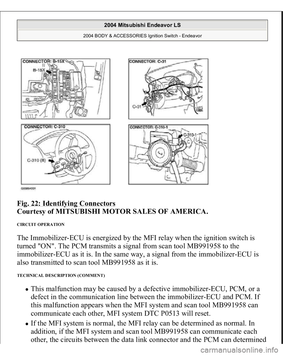
Fig. 22: Identifying Connectors
Courtesy of MITSUBISHI MOTOR SALES OF AMERICA.
CIRCUIT OPERATION The Immobilizer-ECU is energized by the MFI relay when the ignition switch is
turned "ON". The PCM transmits a signal from scan tool MB991958 to the
immobilizer-ECU as it is. In the same way, a signal from the immobilizer-ECU is
also transmitted to scan tool MB991958 as it is. TECHNICAL DESCRIPTION (COMMENT)
This malfunction may be caused by a defective immobilizer-ECU, PCM, or a
defect in the communication line between the immobilizer-ECU and PCM. If
this malfunction appears when the MFI system and scan tool MB991958 can
communicate each other, MFI system DTC P0513 will reset. If the MFI system is normal, the MFI relay can be determined as normal. In
addition, if the MFI system and scan tool MB991958 can communicate each
other, the circuits between the data link connecto
r and the PCM can determined
2004 Mitsubishi Endeavor LS
2004 BODY & ACCESSORIES Ignition Switch - Endeavor