Page 2666 of 3870
Fig. 116: Displaying "Data List"
Courtesy of MITSUBISHI MOTOR SALES OF AMERICA.
7. The multi-center display shows whether the ignition key, which has been
inserted in the switch, can be rewritten and how many ignition keys have ever
been re
gistered.
2004 Mitsubishi Endeavor LS
2004 BODY & ACCESSORIES Ignition Switch - Endeavor
Page 2667 of 3870
Fig. 117: Displaying "Multi
-Center Display"
Courtesy of MITSUBISHI MOTOR SALES OF AMERICA.
2004 Mitsubishi Endeavor LS
2004 BODY & ACCESSORIES Ignition Switch - Endeavor
Page 2726 of 3870
2004 BODY & ACCESSORIES
Keyless Entry System - Endeavor
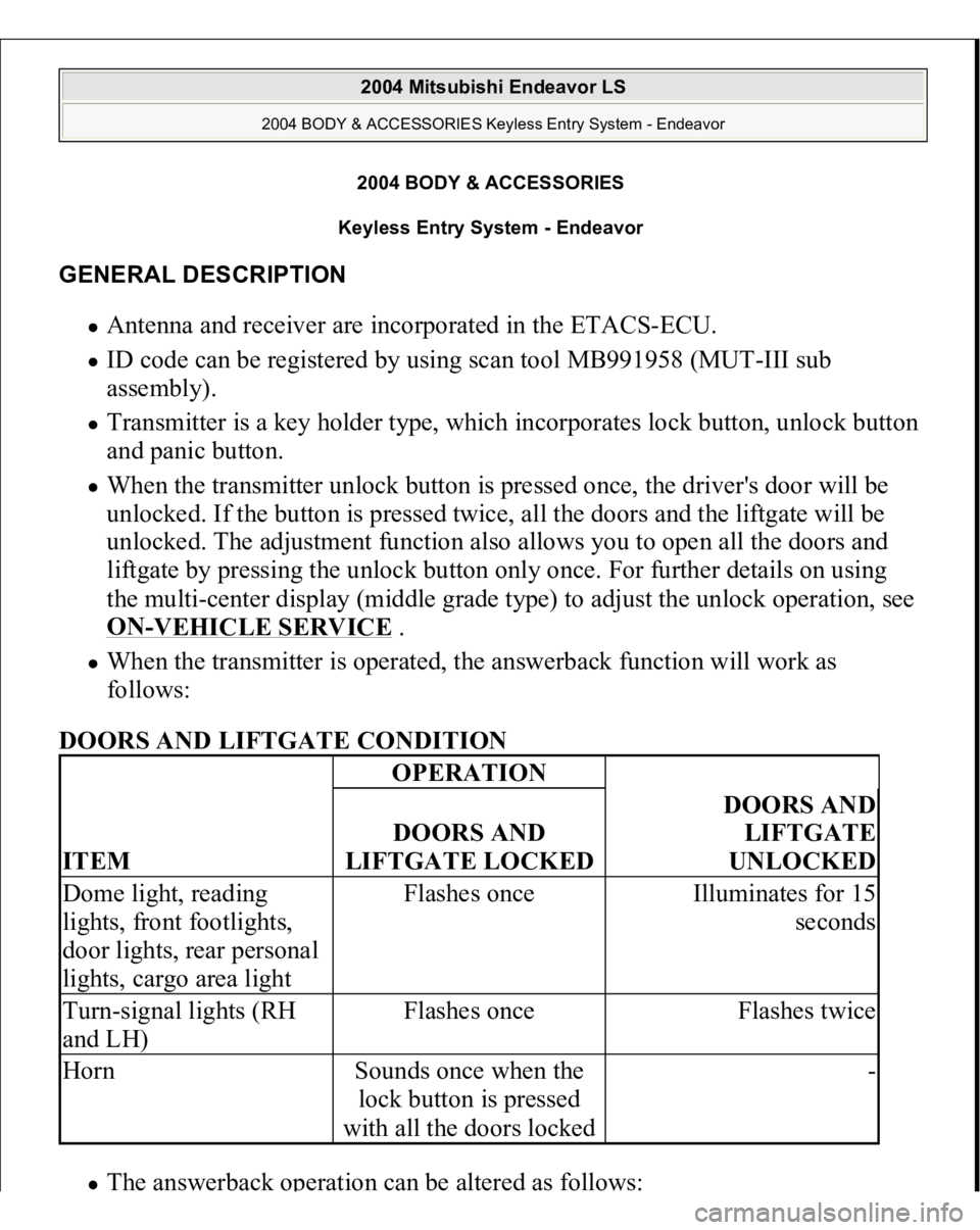
GENERAL DESCRIPTION
Antenna and receiver are incorporated in the ETACS-ECU. ID code can be registered by using scan tool MB991958 (MUT-III sub
assembly). Transmitter is a key holder type, which incorporates lock button, unlock button
and panic button. When the transmitter unlock button is pressed once, the driver's door will be
unlocked. If the button is pressed twice, all the doors and the liftgate will be
unlocked. The adjustment function also allows you to open all the doors and
liftgate by pressing the unlock button only once. For further details on using
the multi-center display (middle grade type) to adjust the unlock operation, see
ON
-VEHICLE SERVICE
.
When the transmitter is operated, the answerback function will work as
follows:
DOORS AND LIFTGATE CONDITION The answerback o
peration can be altered as follows:
ITEM
OPERATIONDOORS AND
LIFTGATE LOCKED
DOORS AND
LIFTGATE
UNLOCKED
Dome light, reading
lights, front footlights,
door lights, rear personal
lights, cargo area light
Flashes once
Illuminates for 15
seconds
Turn-signal lights (RH
and LH)
Flashes once
Flashes twice
Horn
Sounds once when the
lock button is pressed
with all the doors locked
-
2004 Mitsubishi Endeavor LS
2004 BODY & ACCESSORIES Keyless Entry System - Endeavor
2004 Mitsubishi Endeavor LS
2004 BODY & ACCESSORIES Keyless Entry System - Endeavor
Page 2727 of 3870
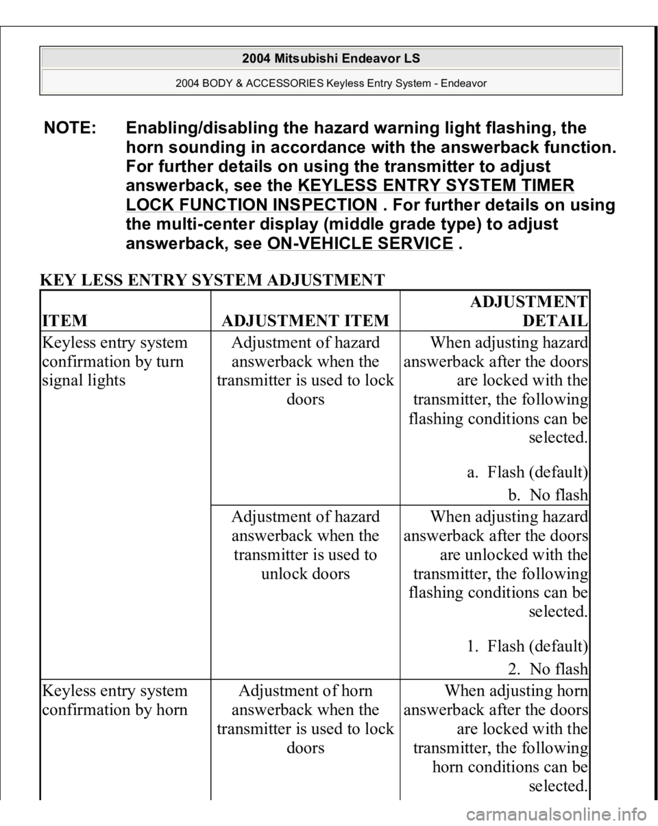
KEY LESS ENTRY SYSTEM ADJUSTMENT NOTE: Enabling/disabling the hazard warning light flashing, the
horn sounding in accordance with the answerback function.
For further details on using the transmitter to adjust
answerback, see the KEYLESS ENTRY SYSTEM TIMER
LOCK FUNCTION INSPECTION
. For further details on using
the multi-center display (middle grade type) to adjust
answerback, see ON
-VEHICLE SERVICE
.
ITEM
ADJUSTMENT ITEM
ADJUSTMENT
DETAIL
Keyless entry system
confirmation by turn
signal lights
Adjustment of hazard
answerback when the
transmitter is used to lock
doors
When adjusting hazard
answerback after the doors
are locked with the
transmitter, the following
flashing conditions can be
selected.
a. Flash (default)
b. No flash
Adjustment of hazard
answerback when the
transmitter is used to
unlock doors
When adjusting hazard
answerback after the doors
are unlocked with the
transmitter, the following
flashing conditions can be
selected.
1. Flash (default)
2. No flash
Keyless entry system
confirmation by horn
Adjustment of horn
answerback when the
transmitter is used to lock
doors
When adjusting horn
answerback after the doors
are locked with the
transmitter, the following
horn conditions can be
selected.
2004 Mitsubishi Endeavor LS
2004 BODY & ACCESSORIES Keyless Entry System - Endeavor
Page 2728 of 3870
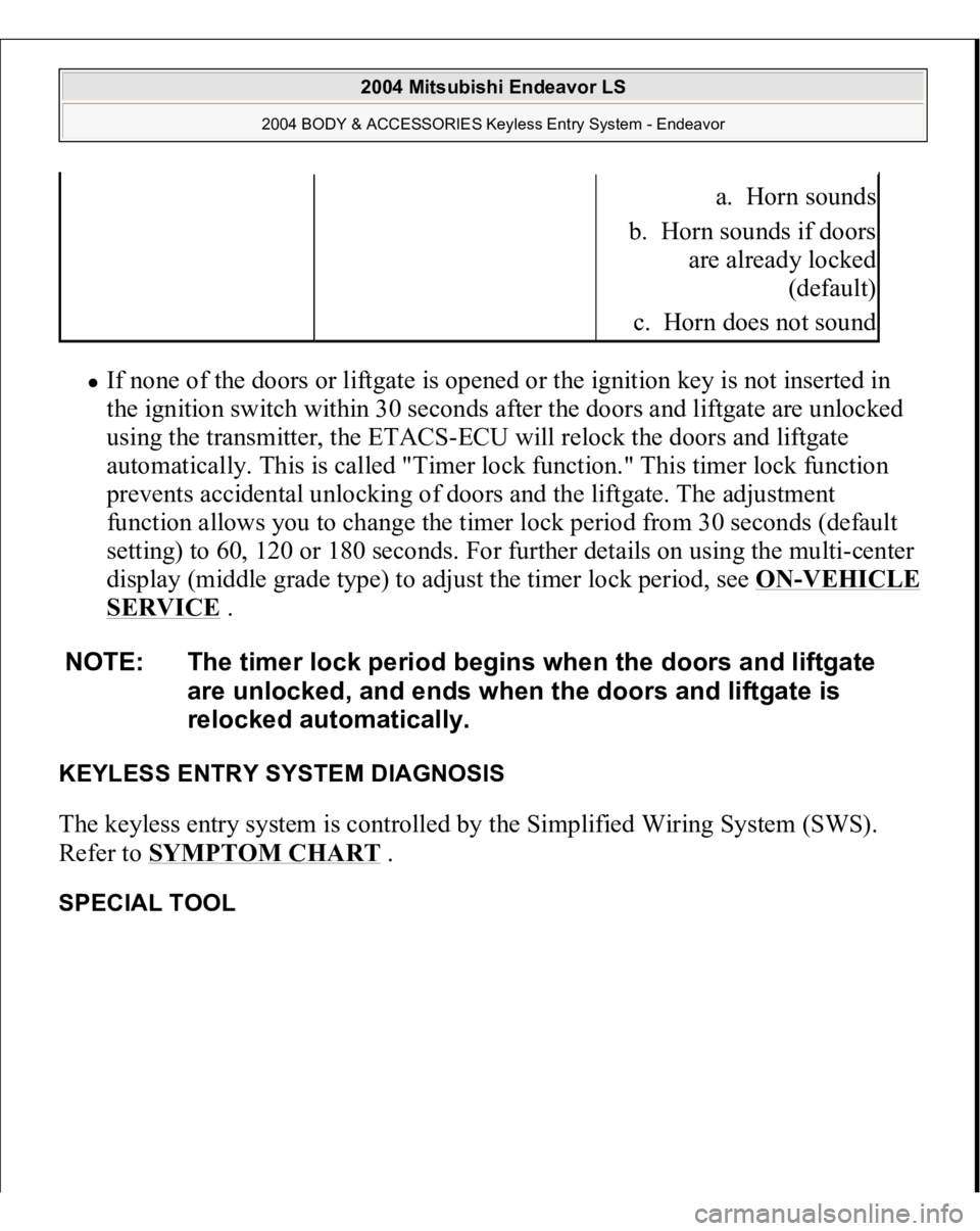
If none of the doors or liftgate is opened or the ignition key is not inserted in
the ignition switch within 30 seconds after the doors and liftgate are unlocked
using the transmitter, the ETACS-ECU will relock the doors and liftgate
automatically. This is called "Timer lock function." This timer lock function
prevents accidental unlocking of doors and the liftgate. The adjustment
function allows you to change the timer lock period from 30 seconds (default
setting) to 60, 120 or 180 seconds. For further details on using the multi-center
display (middle grade type) to adjust the timer lock period, see ON
-VEHICLE
SERVICE
.
KEYLESS ENTRY SYSTEM DIAGNOSIS The keyless entry system is controlled by the Simplified Wiring System (SWS).
Refer to SYMPTOM CHART
.
SPECIAL TOOL
a. Horn sounds
b. Horn sounds if doors
are already locked
(default)
c. Horn does not sound
NOTE: The timer lock period begins when the doors and liftgate
are unlocked, and ends when the doors and liftgate is
relocked automatically.
2004 Mitsubishi Endeavor LS
2004 BODY & ACCESSORIES Keyless Entry System - Endeavor
Page 3120 of 3870
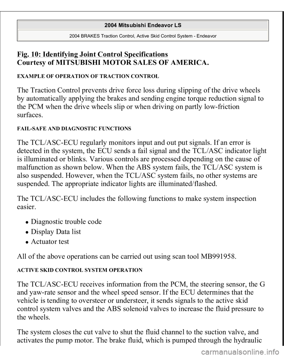
Fig. 10: Identifying Joint Control Specification
s
Courtesy of MITSUBISHI MOTOR SALES OF AMERICA.
EXAMPLE OF OPERATION OF TRACTION CONTROL The Traction Control prevents drive force loss during slipping of the drive wheels
by automatically applying the brakes and sending engine torque reduction signal to
the PCM when the drive wheels slip or when driving on partly low-friction
surfaces. FAIL-SAFE AND DIAGNOSTIC FUNCTIONS The TCL/ASC-ECU regularly monitors input and out put signals. If an error is
detected in the system, the ECU sends a fail signal and the TCL/ASC indicator light
is illuminated or blinks. Various controls are processed depending on the cause of
malfunction as shown below. When the ABS system fails, the TCL/ASC system is
also suspended. However, when the TCL/ASC system fails, no other systems are
suspended. The appropriate indicator lights are illuminated/flashed.
The TCL/ASC-ECU includes the following functions to make system inspection
easier.
Diagnostic trouble code Display Data list Actuator test
All of the above operations can be carried out using scan tool MB991958.
ACTIVE SKID CONTROL SYSTEM OPERATION The TCL/ASC-ECU receives information from the PCM, the steering sensor, the G
and yaw-rate sensor and the wheel speed sensor. If the ECU determines that the
vehicle is tending to oversteer or understeer, it sends signals to the active skid
control system valves and the ABS solenoid valves to increase the fluid pressure to
the wheels.
The system closes the cut valve to shut the fluid channel to the suction valve, and
activates the
pum
p motor. The brake fluid, which is
pum
ped throu
gh the h
ydraulic
2004 Mitsubishi Endeavor LS
2004 BRAKES Traction Control, Active Skid Control System - Endeavor
Page 3135 of 3870
When you check if an TCL/ASC DTC will be displayed again after the DTC has
been erased, you should duplicate the TCL/ASC DTC set conditions. Depending on
the detection timing and set conditions for the specific TCL/ASC DTC, you must
either drive the vehicle or turn the engine off and restart it. To set the proper
conditions for that DTC again, refer to "TCL/ASC DTC SET CONDITIONS
" for
each TCL/ASC DTC that you are trying to reset.
TCL/ASC DIAGNOSTIC TROUBLESHOOTING STRATEGY Use these steps to plan your diagnostic strategy. If you follow them carefully, you
will be sure that you have exhausted most of the possible ways to find an TCL/ASC
fault.
1. Gather information about the problem from the customer.
2. Verify that the condition described by the customer exists.
3. Check the vehicle for any TCL/ASC DTC.
4. If you cannot verify the condition and there are no TCL/ASC DTCs, the
malfunction is intermittent. Refer to HOW TO COPE WITH
INTERMITTENT MALFUNCTIONS
.
5. If you can verify the condition but there are no TCL/ASC DTCs, or the system
cannot communicate with the scan tool, check that the basic brake system is
operating properly.
If the basic brake system is not operating properly, refer to the BASIC BRAKE SYSTEM DIAGNOSIS
, .
If the basic brake system is operating properly, refer to SYMPTOM CHART
.
6. If there is an TCL/ASC DTC, record the number of the DTC, then erase the
DTC from the memory using the scan tool.
7. Duplicate the TCL/ASC DTC set conditions to see if the same TCL/ASC DTC
will set again.
If the same TCL/ASC DTC sets again or the TCL/ASC DTC cannot be
erased, perform the diagnostic procedures for the DTC. Refer to
DIAGNOSTIC TROUBLE CODE CHART
.
If you cannot
get the same TCL/ASC DTC to set a
gain, the malfunction is
2004 Mitsubishi Endeavor LS
2004 BRAKES Traction Control, Active Skid Control System - Endeavor
Page 3138 of 3870
4. Connect special tool MB991910 to the V. C. I.
5. Connect special tool to the data link connector.
6. Turn the V. C. I. power switch to the "ON" position.
7. Start the MUT-III system on the personal computer. HOW TO READ AND ERASE DIAGNOSTIC TROUBLE CODES Required Special Tools:
MB991958: Scan Tool (MUT-III Sub Assembly)
MB991824: Vehicle Communication Interface (V. C. I.) MB991827: MUT-III USB Cable MB991910: MUT-III Main Harness A
1. Connect scan tool MB991958 to the data link connec
tor.
NOTE: When the V.C.I. is energized, the V.C.I. indicator light
will be illuminated in a green color.
NOTE: Disconnect the scan tool in the reverse order of the
connecting sequence, making sure that the ignition
switch is at the "LOCK" (OFF) position.
CAUTION: To prevent damage to scan tool MB991958, always
turn the ignition switch to the "LOCK" (OFF) position
before connecting or disconnecting scan tool
MB991958.
NOTE: If the battery voltage is low, diagnostic trouble codes will
not be set. Check the battery if scan tool MB991958 does
not display.
2004 Mitsubishi Endeavor LS
2004 BRAKES Traction Control, Active Skid Control System - Endeavor