Page 469 of 3870
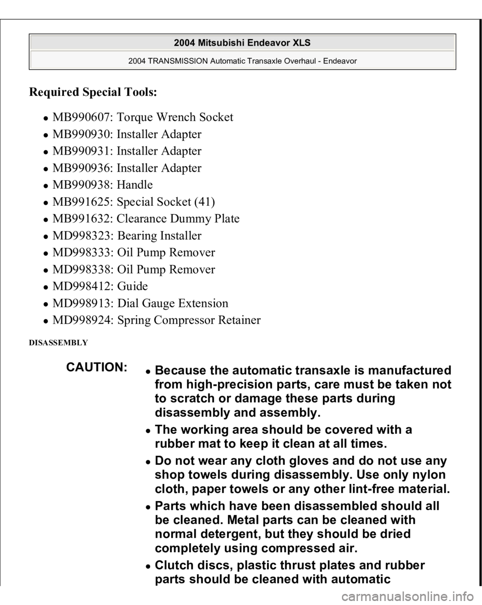
Required Special Tools:
MB990607: Torque Wrench Socket MB990930: Installer Adapter MB990931: Installer Adapter MB990936: Installer Adapter MB990938: Handle MB991625: Special Socket (41) MB991632: Clearance Dummy Plate MD998323: Bearing Installer MD998333: Oil Pump Remover MD998338: Oil Pump Remover MD998412: Guide MD998913: Dial Gauge Extension MD998924: Spring Compressor Retainer
DISASSEMBLY
CAUTION:
Because the automatic transaxle is manufactured
from high-precision parts, care must be taken not
to scratch or damage these parts during
disassembly and assembly. The working area should be covered with a
rubber mat to keep it clean at all times. Do not wear any cloth gloves and do not use any
shop towels during disassembly. Use only nylon
cloth, paper towels or any other lint-free material. Parts which have been disassembled should all
be cleaned. Metal parts can be cleaned with
normal detergent, but they should be dried
completely using compressed air. Clutch discs, plastic thrust plates and rubber
parts should be cleaned with automatic
2004 Mitsubishi Endeavor XLS
2004 TRANSMISSION Automatic Transaxle Overhaul - Endeavor
Page 604 of 3870
MB991629: Spring Compressor MD998907: Spring Compressor MD998924: Spring Compressor Retainer
DISASSEMBLY SERVICE POINT << A >> SNAP RING REMOVAL 1. Set special tools MD998907 and MD998924 as shown in the illustration.
2. Compress the return spring and remove the snap ring.
Fi
g. 150: Usin
g Special Tools And Removin
g Sna
p Rin
g
2004 Mitsubishi Endeavor XLS
2004 TRANSMISSION Automatic Transaxle Overhaul - Endeavor
Page 610 of 3870
Fig. 157: Exploded View Of Reverse And Overdrive Clutch
Courtesy of MITSUBISHI MOTOR SALES OF AMERICA.
Required Special Tools:
MB991629: Spring Compressor MB991789: Spring Compressor MD998924: Spring Compressor Retainer MD999575: S
prin
g Com
pressor
2004 Mitsubishi Endeavor XLS
2004 TRANSMISSION Automatic Transaxle Overhaul - Endeavor
Page 792 of 3870
2004 ENGINE COOLING
Electric Cooling Fans - Endeavor
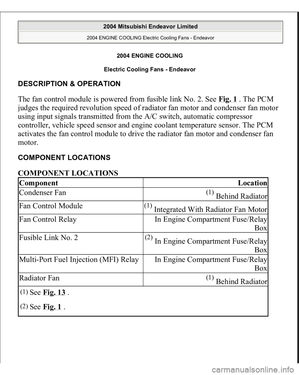
DESCRIPTION & OPERATION The fan control module is powered from fusible link No. 2. See Fig. 1
. The PCM
judges the required revolution speed of radiator fan motor and condenser fan motor
using input signals transmitted from the A/C switch, automatic compressor
controller, vehicle speed sensor and engine coolant temperature sensor. The PCM
activates the fan control module to drive the radiator fan motor and condenser fan
motor. COMPONENT LOCATIONS COMPONENT LOCATIONS Component
Location
Condenser Fan
(1) Behind Radiator
Fan Control Module
(1) Integrated With Radiator Fan Motor
Fan Control Relay
In Engine Compartment Fuse/Relay
Box
Fusible Link No. 2
(2) In Engine Compartment Fuse/Relay
Box
Multi-Port Fuel Injection (MFI) Relay
In Engine Compartment Fuse/Relay
Box
Radiator Fan
(1) Behind Radiator
(1)
See Fig. 13
.
(2)
See Fig. 1
.
2004 Mitsubishi Endeavor Limited
2004 ENGINE COOLING Electric Cooling Fans - Endeavor
2004 Mitsubishi Endeavor Limited
2004 ENGINE COOLING Electric Cooling Fans - Endeavor
Page 1093 of 3870
2004 MITSUBISH
I
Endeavor
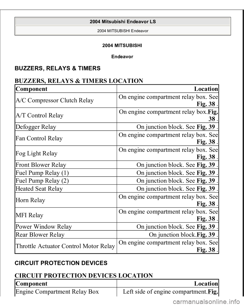
BUZZERS, RELAYS & TIMERS BUZZERS, RELAYS & TIMERS LOCATION CIRCUIT PROTECTION DEVICES CIRCUIT PROTECTION DEVICES LOCATION Component
Location
A/C Compressor Clutch Relay
On engine compartment relay box. See
Fig. 38
.
A/T Control Relay
On engine compartment relay box.Fig.
38 .
Defogger Relay
On junction block. See Fig. 39
.
Fan Control Relay
On engine compartment relay box. See
Fig. 38
.
Fog Light Relay
On engine compartment relay box. See
Fig. 38
.
Front Blower Relay
On junction block. See Fig. 39
.
Fuel Pump Relay (1)
On junction block. See Fig. 39
.
Fuel Pump Relay (2)
On junction block. See Fig. 39
.
Heated Seat Relay
On junction block. See Fig. 39
.
Horn Relay
On engine compartment relay box. See
Fig. 38
.
MFI Relay
On engine compartment relay box. See
Fig. 38
.
Power Window Relay
On junction block. See Fig. 39
.
Rear Blower Relay
On junction block.Fig. 39
.
Throttle Actuator Control Motor Relay
On engine compartment relay box. See
Fig. 38
.
Component
Location
Engine Compartment Relay Box
Left side of engine compartment.Fi
g.
2004 Mitsubishi Endeavor LS
2004 MITSUBISHI Endeavor
2004 Mitsubishi Endeavor LS
2004 MITSUBISHI Endeavor
Page 1098 of 3870
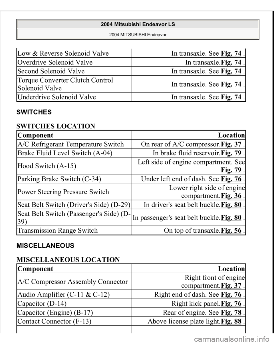
SWITCHES SWITCHES LOCATION MISCELLANEOUS MISCELLANEOUS LOCATION Low & Reverse Solenoid Valve
In transaxle. See Fig. 74
.
Overdrive Solenoid Valve
In transaxle.Fig. 74
.
Second Solenoid Valve
In transaxle. See Fig. 74
.
Torque Converter Clutch Control
Solenoid Valve
In transaxle. See Fig. 74
.
Underdrive Solenoid Valve
In transaxle. See Fig. 74
.
Component
Location
A/C Refrigerant Temperature Switch
On rear of A/C compressor.Fig. 37
.
Brake Fluid Level Switch (A-04)
In brake fluid reservoir.Fig. 79
.
Hood Switch (A-15)
Left side of engine compartment. See
Fig. 79
.
Parking Brake Switch (C-34)
Under left end of dash. See Fig. 76
.
Power Steering Pressure Switch
Lower right side of engine
compartment.Fig. 36
.
Seat Belt Switch (Driver's Side) (D-29)
In driver's seat belt buckle.Fig. 80
.
Seat Belt Switch (Passenger's Side) (D-
39)
In passenger's seat belt buckle.Fig. 80
.
Transmission Range Switch
On top of transaxle.Fig. 56
.
Component
Location
A/C Compressor Assembly Connector
Right front of engine
compartment.Fig. 37
.
Audio Amplifier (C-11 & C-12)
Right end of dash. See Fig. 76
.
Capacitor (D-14)
Right kick panel.Fig. 76
.
Capacitor (Engine) (B-17)
Rear of engine. See Fig. 78
.
Contact Connector (F-13)
Above license plate light.Fig. 88
.
2004 Mitsubishi Endeavor LS
2004 MITSUBISHI Endeavor
Page 1199 of 3870
Courtesy of MITSUBISHI MOTOR SALES OF AMERICA
.
CIRCUIT OPERATION
The fan control module is powered from fusible link number 2. The PCM judges the required revolution speed of radiator fan motor and
condenser fan motor using the input signals transmitted from A/C switch,
automatic compressor controller, vehicle speed sensor and engine coolant
temperature sensor. The PCM activates the fan control module to drive the
radiator fan motor and condenser fan motor.
TECHNICAL DESCRIPTION
The cause could be a malfunction of the fan control module power supply or
ground circuit. The cause could also be a malfunction of the fan control module or the PCM.
TROUBLESHOOTING HINTS
Malfunction of fusible link Malfunction of fan control relay Malfunction of MFI relay Malfunction of fan control module Malfunction of PCM Damaged wiring harness or connector
DIAGNOSIS Required Special Tools:
MB991223: Harness Set MB991923: Power Plant ECU Check Harness
STEP 1. Check the circuit at fan control module connector A-23 (terminal
3).
1. Disconnect fan control module connector A-23, and measure at the
harness side connector.
2004 Mitsubishi Endeavor Limited 2004 ENGINE Engine Cooling - Endeavor
Page 1220 of 3870
Courtesy of MITSUBISHI MOTOR SALES OF AMERICA
.
STEP 14. Check the symptoms.
Q: Do the radiator fan and condenser fan operate correctly?
YES: The procedure is complete.
NO: Return to Step 1 .
INSPECTION PROCEDURE 4: Radiator Fan and Condenser Fan do not Change Speed or Stop Radiator Fan and Condenser Fan Drive Circuit Refer to INSPECTION PROCEDURE 3: RADIATOR FAN AND CONDENSER FAN DO NOT OPERATE
.
CIRCUIT OPERATION
The fan control module is powered from fusible link number 2. The PCM judges the required revolution speed of radiator fan motor and
condenser fan motor using the input signals transmitted from A/C switch,
automatic compressor controller, vehicle speed sensor and engine coolant
temperature sensor. The PCM activates the fan control module to drive the
radiator fan motor and condenser fan motor.
TECHNICAL DESCRIPTION The fan controller has variable control of the radiator fan motor and the condenser
fan motor speeds using signals transmitted from the PCM. TROUBLESHOOTING HINTS NOTE: If the engine coolant temperature reaches 110°C (230°F) or
higher, the radiator fan control runs the radiator fan for up
to 5 minutes even after the ignition switch is turned to the
"LOCK" (OFF) position [the fan stops its rotation when the
engine coolant temperature decreases to 110°C (230° F) or
lower.]
2004 Mitsubishi Endeavor Limited 2004 ENGINE Engine Cooling - Endeavor