2004 JEEP LIBERTY flat tire
[x] Cancel search: flat tirePage 114 of 374

into the tire pressure display screen and flash the pres-
sure value of the tire that is low or high. This will be
displayed for the rest of the ignition cycle, or until the
C/T, MENU, STEP, or RESET button is pressed.
NOTE:This display will return 60 seconds after the
C/T, MENU, STEP, or RESET button is pressed. If a tire is
low or high, you should correct your tire inflation
pressure as soon as possible and inspect all of your tires.
Refer to STARTING AND OPERATING Ð TIRES AND
WHEELS for more details.
Once the low or high tire pressure message has occurred,
it will continue to blink until the tire pressure is cor-
rected.
2. If the spare tire pressure has exceeded the low or high
pressure allowed, the TPM system will display a message
in the EVIC for 60 seconds and sound a chime each
ignition cycle.NOTE:This message will return every ignition cycle,
until the tire pressures are corrected.
3. When the vehicle is moving and the EVIC cannot
receive a valid sensor signal from the tire pressure
sensors, the TIRE PRESSURE UNAVAILABLE message
will be displayed for 3 seconds along with a chime. The
display will then shift to the individual tire pressure
display screen and display dashes for the tire or tires that
are affected. If the TIRE PRESSURE UNAVAILABLE
message has been displayed, and valid sensor signals are
received, the EVIC will display the TIRE PRESSURE
NOW AVAILABLE message for 3 seconds along with a
chime. This is meant to inform you when the TPM system
has returned to it's normal operation. This will occur
when valid tire pressure sensor messages have been
received from all 4 road tires. TPM system function may
be temporarily unavailable due to external electromag-
netic interference, such as electronic devices or nearby
radio or TV towers.
114 UNDERSTANDING THE FEATURES OF YOUR VEHICLE
Page 115 of 374

4. In addition to monitoring the vehicle tires, the TPM
system monitors faults within the system. When any
fault has been set, the TPM system will display TIRE
SENSOR BAD/MISSING. Be sure to inspect your tires for
proper inflation pressure. After you determine that your
tires are properly inflated, see your authorized dealer for
service to diagnose the problem with the TPM system.
5. If a road tire is replaced by the spare, the TPM system
will automatically detect that the tires have been
switched (after the ignition has been cycled) and display
SPARE SWAP DETECTED along with a chime. This
could take up to 10 minutes with vehicle speed above 25
mph (40 km/h).
General Information
This device complies with FCC rules part 15 and with
RSS-210 of Industry Canada. Operation is subject to the
following conditions:
1. This device may not cause harmful interference2. This device must accept any interference that may be
received, including interference that may cause undes-
ired operation
Changes or modifications not expressly approved by the
party responsible for compliance could void the user's
authority to operate the device.
For further assistance, questions, or comments about the
TPM system, please call1±877±774±8473.
Customer Programmable Features
Press the MENU button until one of the display choices
following appears:
Language?
When in this display you may select one of five lan-
guages for all display nomenclature, including the trip
computer functions. Press the STEP button while in this
display to select English, Francais, Deutsch, Italiana, or
Espanol. As you continue the displayed information will
be shown in the selected language.
UNDERSTANDING THE FEATURES OF YOUR VEHICLE 115
3
Page 151 of 374

INSTRUMENT CLUSTER DESCRIPTION
1. Tachometer
Indicates the permissible engine revolutions-per-minute
for each gear range. Before reaching the red area, ease up
on the accelerator to prevent engine damage.
2. Turn Signal Indicator Light
The arrows will flash in unison with the exterior
turn signals, when using the multi-function control
lever. A chime will sound if the turn signals are left on
continuously for 2 miles (3 km) until they are deacti-
vated.
3. High Beam Indicator Light
This light shows that the headlights are on high
beam. Pull the multi-function control lever to-
wards the steering wheel to switch the headlights from
high to low beam.4. Speedometer
Indicates vehicle speed.
5. Tire Pressure Monitor Warning Light Ð If Equipped
This light will turn on when there is a low tire
pressure condition. The light will also turn on
if a problem exist with any tire sensor. The light
will remain on until the tire pressure is prop-
erly set or the problem with the sensor is corrected.
This light will turn on momentarily as a bulb check when
the engine is started.
When the ªTire Pressure Monitor Warning Lightº is lit,
one or more of your tires is significantly under-inflated.
You should stop and check your tires as soon as possible,
and inflate them to the proper pressure as indicated on
the vehicle's tire information placard. Driving on a
significantly under-inflated tire causes the tire to over-
heat and can lead to tire failure. Under-inflation also
reduces fuel efficiency and tire tread life, and may affect
UNDERSTANDING YOUR INSTRUMENT PANEL 151
4
Page 152 of 374

the vehicle's handling and stopping ability. Each tire,
including the spare, should be checked monthly when
cold and set to the recommended inflation pressure as
specified on the vehicle placard.
6. 4LO Mode Indicator Light Ð If Equipped
This light alerts the driver that the vehicle is in
the 4 LO four±wheel drive mode. The front and
rear driveshafts are mechanically locked to-
gether forcing the front and rear wheels to
rotate at the same speed.
7. Fog Light Indicator Light Ð If Equipped
This light shows when the front fog lights are on.
8. Malfunction Indicator Light
This light is part of an onboard diagnostic system
called OBD II which monitors engine and auto-
matic transmission control systems. This light
will illuminate when the ignition is in the ON positionbefore engine start. If the bulb does not come on when
turning the ignition key from OFF to ON, have the
condition checked promptly.
Certain conditions such has a loose or missing gas cap,
poor fuel quality, etc. may illuminate the light after
engine start. The vehicle should be serviced if the light
stays on through several typical driving cycles. In most
situations, the vehicle will drive normally and will not
require towing.
When the engine is running, the ªMalfunction Indicator
Lightº may flash to alert of serious conditions that could
lead to immediate loss of power or severe catalytic
converter damage. The vehicle should be serviced as
soon as possible if this occurs.
9. Anti-Lock Warning Light (ABS) Ð If Equipped
This light monitors the Anti-Lock Brake System
(ABS) described elsewhere in this manual. This
152 UNDERSTANDING YOUR INSTRUMENT PANEL
Page 208 of 374

NShifting Procedure....................230
mTrac-LokŸ Rear Axle Ð If Equipped.........231
mParking Brake.........................232
mAnti-Lock Brake System Ð If Equipped.......234
mOn-Road Driving Tips...................236
mOff-Road Driving Tips...................236
NWhen To Use 4L Or 4 Lo (Low) Range......236
NIn Snow, Mud And Sand................237
NHill Climbing........................237
NTraction Downhill.....................238
NAfter Driving Off-Road.................238
mTire Safety Information...................239
NTire Markings........................239NTire Identification Number (TIN)..........243
NTire Loading And Tire Pressure...........244
mTires Ð General Information...............248
NTire Inflation Pressures.................249
NHigh Speed Operation.................250
NRadial-Ply Tires......................251
NTire Spinning........................251
NTread Wear Indicators..................252
NReplacement Tires.....................252
NAlignment And Balance.................253
mTire Pressure Monitor System Ð If Equipped . . . 254
NTire Pressure Monitor System Tire/Wheel
Rotation And Sensor Replacement
Ð If Equipped.......................256
208 STARTING AND OPERATING
Page 234 of 374

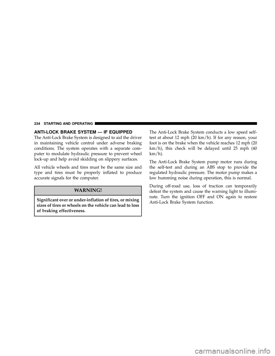
ANTI-LOCK BRAKE SYSTEM Ð IF EQUIPPED
The Anti-Lock Brake System is designed to aid the driver
in maintaining vehicle control under adverse braking
conditions. The system operates with a separate com-
puter to modulate hydraulic pressure to prevent wheel
lock-up and help avoid skidding on slippery surfaces.
All vehicle wheels and tires must be the same size and
type and tires must be properly inflated to produce
accurate signals for the computer.
WARNING!
Significant over or under-inflation of tires, or mixing
sizes of tires or wheels on the vehicle can lead to loss
of braking effectiveness.
The Anti-Lock Brake System conducts a low speed self-
test at about 12 mph (20 km/h). If for any reason, your
foot is on the brake when the vehicle reaches 12 mph (20
km/h), this check will be delayed until 25 mph (40
km/h).
The Anti-Lock Brake System pump motor runs during
the self-test and during an ABS stop to provide the
regulated hydraulic pressure. The motor pump makes a
low humming noise during operation, this is normal.
During off-road use, loss of traction can temporarily
defeat the system and cause the warning light to illumi-
nate. Turn the ignition OFF and ON again to restore
Anti-Lock Brake System function.
234 STARTING AND OPERATING
Page 242 of 374

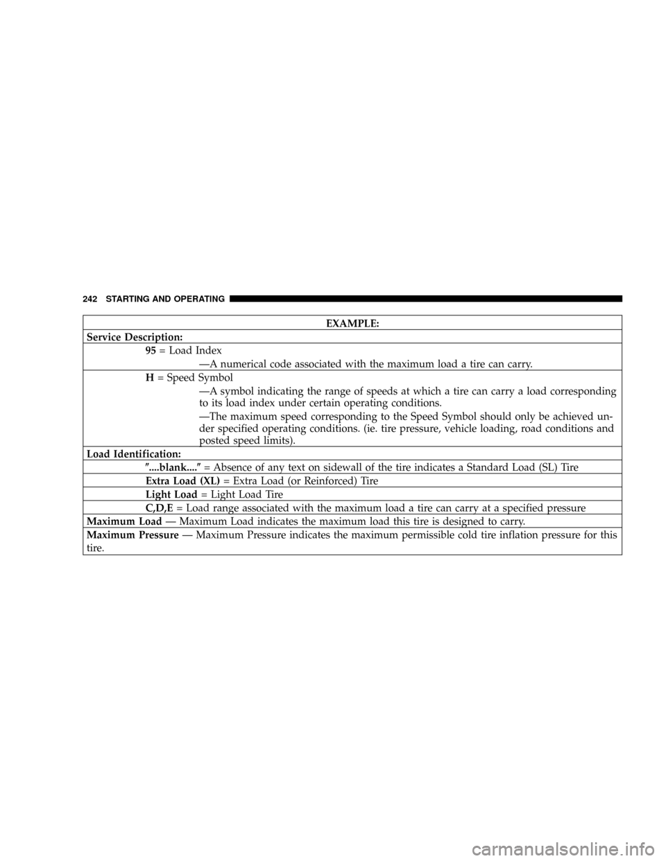
EXAMPLE:
Service Description:
95= Load Index
ÐA numerical code associated with the maximum load a tire can carry.
H= Speed Symbol
ÐA symbol indicating the range of speeds at which a tire can carry a load corresponding
to its load index under certain operating conditions.
ÐThe maximum speed corresponding to the Speed Symbol should only be achieved un-
der specified operating conditions. (ie. tire pressure, vehicle loading, road conditions and
posted speed limits).
Load Identification:
(....blank....(= Absence of any text on sidewall of the tire indicates a Standard Load (SL) Tire
Extra Load (XL)= Extra Load (or Reinforced) Tire
Light Load= Light Load Tire
C,D,E= Load range associated with the maximum load a tire can carry at a specified pressure
Maximum LoadÐ Maximum Load indicates the maximum load this tire is designed to carry.
Maximum PressureÐ Maximum Pressure indicates the maximum permissible cold tire inflation pressure for this
tire.
242 STARTING AND OPERATING
Page 245 of 374

4) the cold tire inflation pressures for the front, rear
and spare tires.
Loading
The vehicle maximum load on the tire must not exceed
the load carrying capacity of the tire on your vehicle. You
will not exceed the tire's load carrying capacity if you
adhere to the loading conditions, tire size and cold tire
inflation pressures specified on the Tire and Loading
Information placard and the Vehicle Loading section of
this manual.
NOTE:Under a maximum loaded vehicle condition,
gross axle weight ratings (GAWR's) for the front and rear
axles must not be exceeded. For further information on
GAWR's, vehicle loading and trailer towing, see the
Vehicle Loading section of this manual.To determine the maximum loading conditions of your
vehicle, locate the statement ªThe combined weight of
occupants and cargo should never exceed XXX kg or XXX
lbs.º on the Tire and Loading Information placard. The
combined weight of occupants, cargo/luggage and
trailer tongue weight (if applicable) should never exceed
the weight referenced here.
Steps for Determining Correct Load Limit
1. Locate the statement ªThe combined weight of occu-
pants and cargo should never exceed XXX poundsº on
your vehicle's placard.
2. Determine the combined weight of the driver and
passengers that will be riding in your vehicle.
STARTING AND OPERATING 245
5