2004 ISUZU TF SERIES end float
[x] Cancel search: end floatPage 171 of 4264

REAR AXLE 4B-7
REAR AXLE ASSEMBLY
General Description
A03R300001
The rear axle assembly is of the semi–floating type in
which the vehicle weight is carried on the axle
housing .
The center line of the pinion gear is below the center
line of the ring gear (hypoid drive).
All parts necessary to transmit power from the
propeller shaft to the rear wheels are enclosed in a
banjo type axle housing.
The 220 mm (8.6 in) ring gear rear axle uses a
conventional ring and pinion gear set to transmit the
driving force of the engine to the rear wheels. This
gear set transfers this driving force at a 90 degree
angle from the propeller shaft to the drive shafts.
The axle shafts are supported at the wheel end of the
shaft by a double tapered roller bearing.
The pinion gear is supported by two tapered roller
bearings. The pinion depth is set by a shim pack
located between the gear end of the pinion and the
roller bearing that is pressed onto the pinion. The
pinion bearing preload is set by crushing a collapsible
spacer between the bearings in the axle housing.
The ring gear is bolted onto the differential cage with
12 bolts.
The differential cage is supported in the axle housing
by two tapered roller bearings. The differential and ring
gear are located in relationship to the pinion by using
selective shims and spacers between the bearing and
the differential cage. To move the ring gear, shims are
deleted from one side and an equal amount are added
to the other side. These shims are also used to
preload the bearings which are pressed onto the
differential cage. Two bearing caps are used to hold
the differential into the rear axle housing.
The differential is used to allow the wheels to turn at
different rates of speed while the rear axle continues
to transmit the driving force. This prevents tire
scuffing when going around corners and prevents
premature wear on internal axle parts.
The rear axle is sealed with a pinion seal, a seal at
each axle shaft end, and by a liquid gasket between
the differential carrier and the axle housing
Page 1313 of 4264
FUEL SYSTEM 6C – 13
Removal
CAUTION: When repair to the fuel system has been
completed, start engine and check the fuel system for
loose connection or leakage. For the fuel system
diagnosis, see Section “Driveability and Emission".
1. Remove fuel tank assembly (9). Refer to “Fuel Tank
Removal" in this section.
2. Disconnect the quick connector (6) of the fuel tube from fuel
gauge unit.
3. Disconnect the quick connector (10) of the evapo tube from
fuel gauge unit.
140R100035
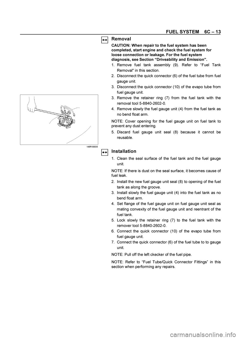
3. Remove the retainer ring (7) from the fuel tank with the
removal tool 5-8840-2602-0.
4.
Remove slowly the fuel gauge unit (4) from the fuel tank as
no bend float arm.
NOTE: Cover opening for the fuel gauge unit on fuel tank to
prevent any dust entering.
5.
Discard fuel gauge unit seal (8) because it cannot be
reusable.
Installation
1. Clean the seal surface of the fuel tank and the fuel gauge
unit.
NOTE: If there is dust on the seal surface, it becomes cause o
f
fuel leak.
2. Install the new fuel gauge unit seal (8) to opening of the fuel
tank as along the groove.
3. Install slowly the fuel gauge unit (4) into the fuel tank as no
bend float arm.
4.
Set flange of the fuel gauge unit on fuel gauge unit seal as
mating convexity of the fuel gauge unit and reentrant of the
fuel tank.
5.
Lock slowly the retainer ring (7) to the fuel tank with the
remover tool 5-8840-2602-0.
6. Connect the quick connector (10) of the evapo tube from
fuel gauge unit.
7.
Connect the quick connector (6) of the fuel tube to to gauge
unit.
NOTE: Pull off the left ckecker of the fuel pipe.
NOTE: Refer to “Fuel Tube/Quick Connector Fittings” in this
section when performing any repairs.
Page 1949 of 4264
ENGINE FUEL (6VE1 3.5L) 6C-7
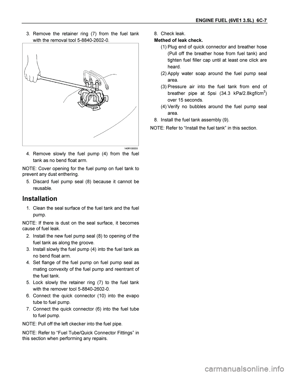
3. Remove the retainer ring (7) from the fuel tank
with the removal tool 5-8840-2602-0.
140R100035
4. Remove slowly the fuel pump (4) from the fuel
tank as no bend float arm.
NOTE: Cover opening for the fuel pump on fuel tank to
prevent any dust enthering.
5. Discard fuel pump seal (8) because it cannot be
reusable.
Installation
1. Clean the seal surface of the fuel tank and the fuel
pump.
NOTE: If there is dust on the seal surface, it becomes
cause of fuel leak.
2. Install the new fuel pump seal (8) to opening of the
fuel tank as along the groove.
3. Install slowly the fuel pump (4) into the fuel tank as
no bend float arm.
4. Set flange of the fuel pump on fuel pump seal as
mating convexity of the fuel pump and reentrant o
f
the fuel tank.
5. Lock slowly the retainer ring (7) to the fuel tank
with the remover tool 5-8840-2602-0.
6. Connect the quick connector (10) into the evapo
tube to fuel pump.
7. Connect the quick connector (6) into the fuel tube
to fuel pump.
NOTE: Pull off the left ckecker into the fuel pipe.
NOTE: Refer to “Fuel Tube/Quick Connector Fittings” in
this section when performing any repairs.
8. Check leak.
Methed of leak check.
(1) Plug end of quick connector and breather hose
(Pull off the breather hose from fuel tank) and
tighten fuel filler cap until at least one click are
heard.
(2)
Apply water soap around the fuel pump seal
area.
(3) Pressure air into the fuel tank from end o
f
breather pipe at 5psi (34.3 kPa/2.8kgf/cm2)
over 15 seconds.
(4) Verify no bubbles around the fuel pump seal
area.
8. Install the fuel tank assembly (9).
NOTE: Refer to “Install the fuel tank” in this section.
Page 2533 of 4264
ENGINE FUEL (C24SE) 6C-9
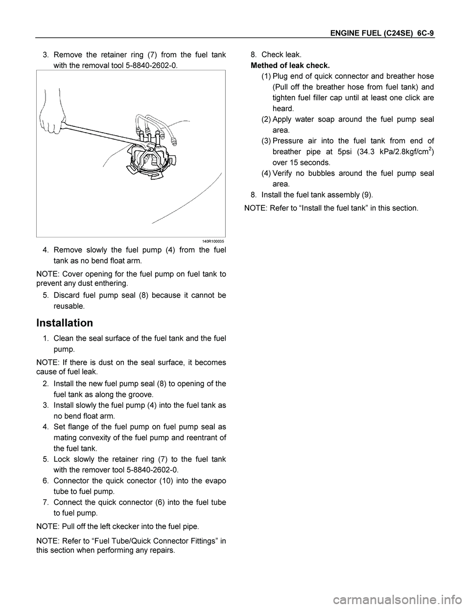
3. Remove the retainer ring (7) from the fuel tank
with the removal tool 5-8840-2602-0.
140R100035
4. Remove slowly the fuel pump (4) from the fuel
tank as no bend float arm.
NOTE: Cover opening for the fuel pump on fuel tank to
prevent any dust enthering.
5. Discard fuel pump seal (8) because it cannot be
reusable.
Installation
1. Clean the seal surface of the fuel tank and the fuel
pump.
NOTE: If there is dust on the seal surface, it becomes
cause of fuel leak.
2. Install the new fuel pump seal (8) to opening of the
fuel tank as along the groove.
3. Install slowly the fuel pump (4) into the fuel tank as
no bend float arm.
4. Set flange of the fuel pump on fuel pump seal as
mating convexity of the fuel pump and reentrant o
f
the fuel tank.
5. Lock slowly the retainer ring (7) to the fuel tank
with the remover tool 5-8840-2602-0.
6. Connector the quick conector (10) into the evapo
tube to fuel pump.
7. Connect the quick connector (6) into the fuel tube
to fuel pump.
NOTE: Pull off the left ckecker into the fuel pipe.
NOTE: Refer to “Fuel Tube/Quick Connector Fittings” in
this section when performing any repairs.
8. Check leak.
Methed of leak check.
(1) Plug end of quick connector and breather hose
(Pull off the breather hose from fuel tank) and
tighten fuel filler cap until at least one click are
heard.
(2) Apply water soap around the fuel pump seal
area.
(3) Pressure air into the fuel tank from end o
f
breather pipe at 5psi (34.3 kPa/2.8kgf/cm2)
over 15 seconds.
(4) Verify no bubbles around the fuel pump seal
area.
8. Install the fuel tank assembly (9).
NOTE: Refer to “Install the fuel tank” in this section.