Page 3394 of 4264
 Yes No
1
2
3
4
5Was the Antitheft System Check
performed?
Recheck the DTC.
1. Key position is “OFF�")
11B – 48 ANTITHEFT SYSTEM
DTC 28 Input Immobilizer short circuit to ground
Step Action Value (s) Yes No
1
2
3
4
5Was the Antitheft System Check
performed?
Recheck the DTC.
1. Key position is “OFF”.
2. Install the Tech-2 on vehicle.
3. Key position is “ON”.
4. Check the DTC on the Tech-2.
Is DTC 28 stored?
Check the driver door locking motor function.
line circuit.
1. Key position is “OFF”.
2. Install the Tech-2 on vehicle.
3. Key position is “ON”.
4. Check the antitheft/Immobilizer communi-
cation line circuit for short to voltage, short to
ground.
Also, check the ICU and ACU ignition feed
circuits for an open or short to ground and
the ICU and ACU ground circuit for an open.
Was a problem found?
Repair or replace the antitheft/Immobilizer
communication line circuit.
Was the action complete?
Replace the antitheft control unit (ACU).
IMPORTANT: The replacement ACU must be
programmed the security data by the Tech-2.
Was the action complete?—
—
—
—
—Go to Step 2
Go to Step 3
Go to Step 4
Verify repair
Verify repairGo to antitheft
System Check
Refer to
Diagnostic Aids
Go to Step 5
—
—
Page 3395 of 4264
 Yes No
1
2
3
4
5Was the Antitheft System Check
performed?
Recheck the DTC.
1. Key position is “OFF”.
2. Instal")
ANTITHEFT SYSTEM 11B – 49
DTC 29 Broken Wire To Immobilizer
Step Action Value (s) Yes No
1
2
3
4
5Was the Antitheft System Check
performed?
Recheck the DTC.
1. Key position is “OFF”.
2. Install the scan tool on vehicle.
3. Key position is “ON”.
4. Check the DTC on the Tech-2.
Is DTC 29 stored?
Check the antitheft/immobilizer communication
line circuit.
1. Key position is “OFF”.
2. Disconnect the antitheft control unit (ACU).
3. Disconnect the immobilizer control unit (ICU).
4. Check the antitheft/Immobilizer communi-
cation line circuit for an open, short to
ground.
Also, check the ICU and ACU ignition feed
circuits for an open or short to ground and
the ICU and ACU ground circuit for an open.
Was a problem found?
Repair or replace the antitheft/Immobilizer
communication line circuit.
Was the action complete?
Replace the antitheft control unit (ACU).
IMPORTANT: The replacement ACU must be
programmed the security data by the Tech-2.
Was the action complete?—
—
—
—
—Go to Step 2
Go to Step 3
Go to Step 4
Verify repair
Verify repairGo to antitheft
System Check
Refer to
Diagnostic Aids
Go to Step 5
—
—
Page 3406 of 4264
 Yes No
1
2
3
4
5
6Was the Antitheft System Check
performed?
Recheck the DTC.
1. Key")
11B – 60 ANTITHEFT SYSTEM
DTC 50 A/D Converter Defect Or Battery Voltage Less Than 9 Volt
Step Action Value (s) Yes No
1
2
3
4
5
6Was the Antitheft System Check
performed?
Recheck the DTC.
1. Key position is “OFF”.
2. Install the Tech-2 on vehicle.
3. Key position is “ON”.
4. Check the DTC on the Tech-2.
Is DTC 50 stored?
Check the antilock system voltage.
1. Key position is “OFF”.
2. Install the Tech-2 on vehicle.
3. Key position is “ON”.
4. Observe to display system voltage data with
the Tech-2.
Is the voltage near the specified value ?
1. Key position is “OFF”.
2. Check the battery voltage.
3. If a problem found, repair as necessary.
(Chage battery)
Was the problem found?
1. Check the ignition feed circuit for an open,
short to ground.
Also, check the ACU ground circuit for
damage.
2. If a problem found, repair as necessary.
Was the problem found?
Replace the antitheft control unit (ACU).
IMPORTANT:The replacement ACU must be
programmed the security data by the Tech-2.
Was the action complete?—
—
12V
—
—
—Go to Step 2
Go to Step 3
Go to Step 7
Verify repair
Verify repair
Verify repairGo to antitheft
System Check
Refer to
Diagnostic Aids
Go to Step 4
Go to Step 5
Refer to
Diagnostic Aids
—
Page 3436 of 4264

3B-6 POWER-ASSISTED STEERING SYSTEM
Steering Column
This illustration is based on the RHD model.
RTW43BLF000101
WARNING: TO AVOID DEPLOYMENT WHEN
TROUBLE-SHOOTING THE SRS SYSTEM, DO NOT
USE ELECTRICAL TEST EQUIPMENT, SUCH AS
BATTERY-POWERED OR A/C-POWERED VOLT-
METER, OHMMETER, ETC., OR ANY TYPE OF
ELECTRICAL EQUIPMENT OTHER THAN SPECIFIED
IN THIS MANUAL. DO NOT USE A NON-POWERED
PROBE-TYPE TESTER.
INSTRUCTION IN THIS MANUAL MUST BE
FOLLOWED CAREFULLY, OTHERWISE PERSONAL
INJURY MAY RESULT.
When servicing a vehicle equipped with Supplemental
Restraint System, pay close attention to all WARNINGS
and CAUTIONS.
For detailed explanation about SRS, refer to Restraints
section.
The steering column has three important features in
addition to the steering function:
1. The column is energy absorbing, designed to
compress in a front-end collision to minimize the
possibility of injury to the driver of the vehicle.
2. The ignition switch and lock are mounted
conveniently on the column.
3. With the column mounted lock, the ignition and
steering operation can be locked to prevent theft o
f
the vehicle.
The column can be disassembled and reassembled.
However, to insure the energy absorbing action, use
only the specified screws, bolts and nuts as designated,
and tighten them to the specified torque.
Handle the column with care when it is removed from
the vehicle. A sharp blow on the end of steering shaft o
r
shift lever, or dropping the assembly could shear o
r
loosen the fastenens that maintain column rigidity.
Page 3463 of 4264

POWER-ASSISTED STEERING SYSTEM 3B-33
Removal
1. Turn the steering wheel so that the vehicle's wheels
are pointing straight ahead.
2. Turn the ignition switch to "LOCK".
3. Disconnect the battery "-" terminal cable, and wait a
t
least 5 minutes. (with SRS air bag)
4. Disconnect the yellow 2-way SRS connector located
under the steering column. (with SRS air bag)
CAUTION: The wheels of the vehicle must be
straight ahead and the steering column in the
"LOCK" position before disconnecting the steering
wheel. Failure to do so will cause the coil assembly
to become uncentered which will cause damage to
the coil assembly. (with SRS air bag)
5. Disable the SRS (Refer to "Disabling the SRS" in
this section). (with SRS air bag)
6. Check the both side hole of the steering cover. (with
SRS air bag)
060R300025
7. Check the position of the pins in a hole. Push the
pin in the direction of an arrow. (with SRS air bag)
060R300032
8. Push the four pins at �
5�
6 mm bar. (with SRS air
bag)
060R300031
9. Cancel the lock four pins. (with SRS air bag)
Page 3466 of 4264
3B-36 POWER-ASSISTED STEERING SYSTEM
3. Align the each snap stud of driver air bag to the hole
of steering wheel. (with SRS air bag)
060R300030
060R300020
4. Push the SRS air bag area1 and area2. At that time
confirm the audible noise of each stud.
060R300036
5. Enable the SRS (Refer to "Enabling the SRS" in this
section). (with SRS air bag)
6. Connect the SRS connector. (with SRS air bag)
7. Connect the battery "-" terminal cable. (with SRS ai
r
bag)
8. Turn the ignition switch to "ON" while watching
warning light and check the light should flash 7 times
and then go off. If lamp does not operate correctly,
refer to Restraints section.
Page 3467 of 4264
POWER-ASSISTED STEERING SYSTEM 3B-37
Steering Wheel
Steering Wheel and Associated Parts
430R300013
Legend
(1) Horn Lead
(2) SRS Connector
(3) Steering Wheel
(4) Steering Wheel Fixing Nut
(5) Inflator Module or Horn Pad
Removal
1. Turn the steering wheel so that the vehicle's wheels
are pointing straight ahead.
2. Turn the ignition switch to "LOCK".
3. Disconnect the battery "-" terminal cable, and wait a
t
least 5 minutes. (with SRS air bag)
4.
Disconnect the yellow 2-way SRS connector located
under the steering column. (with SRS air bag)
CAUTION: The wheels of the vehicle must be
straight ahead and the steering column in the
"LOCK" position before disconnecting the steering
wheel. Failure to do so will cause the coil assembly
to become uncentered which will cause damage to
the coil assembly. (with SRS air bag)
5. Disable the SRS (Refer to "Disabling the SRS" in
this section). (with SRS air bag)
Page 3471 of 4264
POWER-ASSISTED STEERING SYSTEM 3B-41
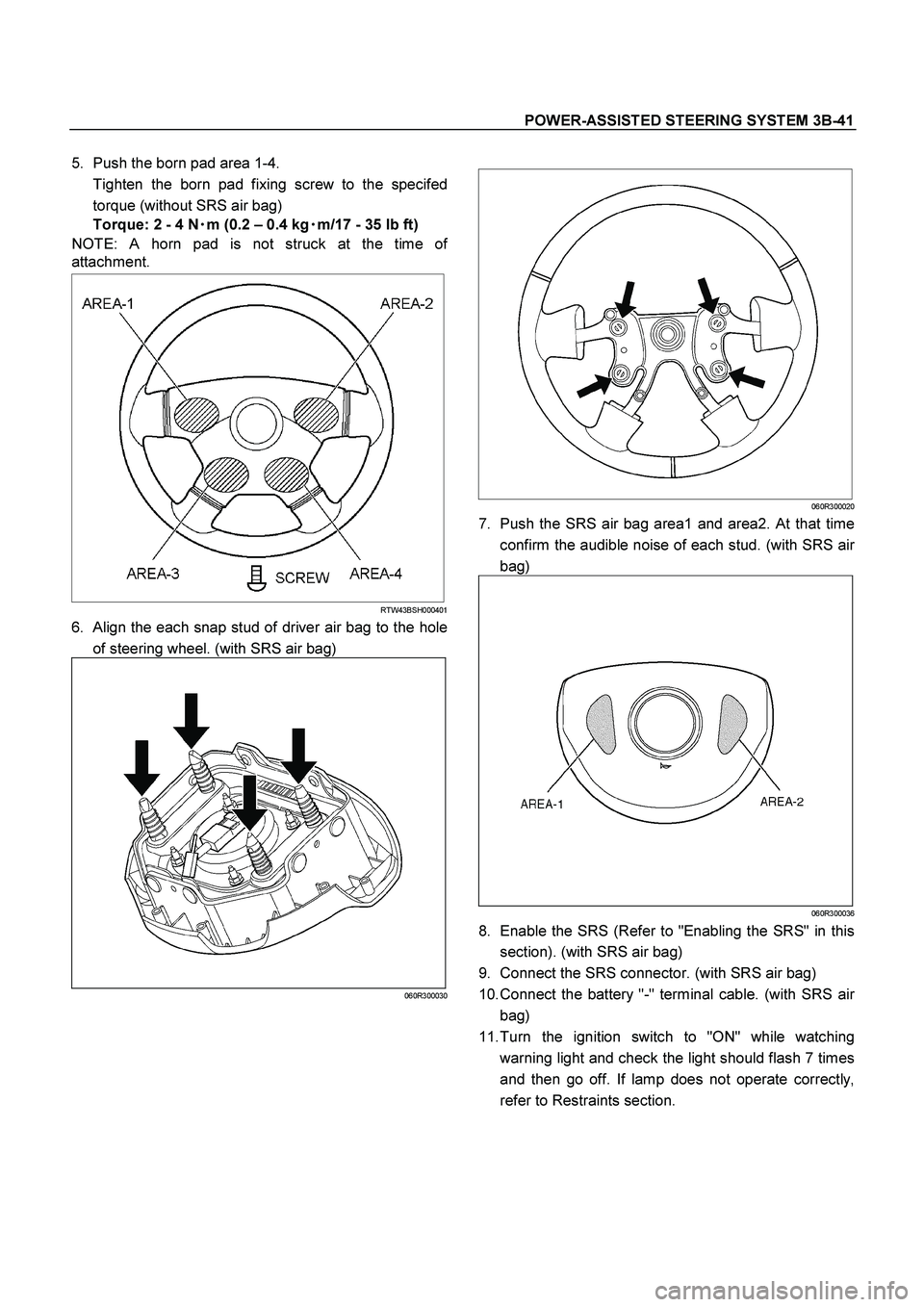
5. Push the born pad area 1-4.
Tighten the born pad fixing screw to the specifed
torque (without SRS air bag)
Torque: 2 - 4 N�
�� �m (0.2 – 0.4 kg�
�� �m/17 - 35 lb ft)
NOTE: A horn pad is not struck at the time o
f
attachment.
RTW43BSH000401
6. Align the each snap stud of driver air bag to the hole
of steering wheel. (with SRS air bag)
060R300030
060R300020
7. Push the SRS air bag area1 and area2. At that time
confirm the audible noise of each stud. (with SRS ai
r
bag)
060R300036
8. Enable the SRS (Refer to "Enabling the SRS" in this
section). (with SRS air bag)
9. Connect the SRS connector. (with SRS air bag)
10. Connect the battery "-" terminal cable. (with SRS ai
r
bag)
11. Turn the ignition switch to "ON" while watching
warning light and check the light should flash 7 times
and then go off. If lamp does not operate correctly,
refer to Restraints section.

060R300030
060R300020
4. Push the SRS air bag area1 and area")
 Horn Lead
(2) SRS Connector
(3) Steering Wheel
(4) Steering Wheel Fixing Nut")