Page 4176 of 4264

7A4-2 UNIT REPAIR (JR405E)
AUTOMATIC TRANSMISSION
DISASSEMBLY
Cleaning the automatic transmission
1. Use compressed steam and /or cleaning oil to thoroughly
clean the outside of the transmission before disassembly.
CAUTION:
Steam under high pressure may cause dirt particles
adhering to the transmission to fly through the air at great
speed. These particles can cause serious eye injury. Wear
protective goggles when steam-cleaning the outside of
the transmission.
2. During disassembly, clean the removed parts with cleaning
oil. Dry the parts with compressed air.
Use Compressed air to clean the transmission oil holes
and oil passages.
Automatic transmission disassembly cautions
��Perform the disassembly procedure in a dust-free
environment to prevent the entry of foreign material into
the transmission.
��Inspect each transmission part as you remove it.
��Carefully check the oil pan and the magnet for foreign
material. This is a good way to estimate transmission
condition.
��Use your bare hands or vinyl gloves to disassemble the
transmission. Do not use ordinary work gloves (loose
threads from the gloves may fall into the transmission and
cause problems).
��Use a plastic hammer to loosen the transmission case
and other aluminum parts during disassembly. Strike
around the parts lightly with the hammer. Do not pry
aluminum parts away from each other with a screwdriver
or similar object.
��Arrange the disassembled parts neatly in the order they
were removed. Cover the parts with a plastic sheet or
similar object to protect them from dust.
Page 4177 of 4264
UNIT REPAIR (JR405E) 7A4-3
Disassembly steps
1. Torque converter
� Pull the torque converter free.
NOTE:
Place a pan beneath the torque converter to catch
automatic transmission fluid (ATF) spillage.
� Draining the ATF from the torque converter.
01ASSY101
2. Turbine sensor and speed sensor
� Remove the turbine sensor from the transmission case.
02ASSY103
�
Remove the speed sensor from the transmission case.
03ASSY106
3. Inhibitor switch
Remove the 2 bolts and the inhibitor switch from the
transmission case.
240L300002
4. Oil pan
� Lift and support the transmission with the holding fixture
and holding fixture base.
Holding fixture: 5-8841-0841-0
Holding fixture base: 5-8840-0003-0
� Remove the drain plug from the oil pan and drain the
ATF from the oil pan.
� Rotate the automatic transmission so that the converte
r
housing is facing up and drain the ATF.
� Rotate the automatic transmission so that the oil pan is
facing up.
� Remove the 19 bolts and the oil pan.
Page 4180 of 4264
7A4-6 UNIT REPAIR (JR405E)
10ASSY116
6. Converter housing
� Position the automatic transmission so that the
converter housing is facing up.
� Remove the 8 bolts and the converter housing.
11ASSY068
7. O-ring
Remove the O-ring from the input shaft.
12ASSY067
8. Oil pump assembly and bearing race
� Remove the 8 bolts.
� Use a slide hammer to remove the oil pump assembly
from the transmission case.
NOTE:
To prevent damage to the oil pump bolt hole threads,
hand-tighten the slide hammer as far as possible.
� Remove the bearing race from the oil pump assembly.
� Inspect the bearing race surfaces for damage.
14ASSY057
9. Input shaft
Pull the input shaft free.
15ASSY049
10.Clutch pack (Reverse and high clutch assembly) and
bearing
� Pull the clutch pack free.
� Remove the bearing from the clutch pack.
Page 4233 of 4264
UNIT REPAIR (JR405E) 7A4-59
18CASE-AY43
�
Use a pin punch to drive the manual plate spring pin into
place.
21CASE-AY48
3. Detent spring
� Install the detent spring and tighten the fixing bolt to the
specified torque.
Torque: 7 N �
��
�
m (61 Ib �
��
�
in)
23CASE-AY53
4. Harness assembly
� Apply automatic transmission fluid to the new O-ring and
install them to the harness assembly.
� Install the harness assembly to the transmission case.
Tighten the fixing bolt to the specified torque.
Torque: 6 N �
��
�
m (52 Ib �
��
�
in)
24ASSY003
5. Low one-way clutch inner race
� Install new seal rings to the low one-way clutch inne
r
race.
25ASSY126
�
Measure the gap between the seal ring and the ring
groove.
If the measured valve is outside the specified range the
low one-way clutch inner race must be replaced.
Sealing ring and ring groove gap:
0.10~0.25 mm (0.0004~0.001 in)
Page 4244 of 4264

7A4-70 UNIT REPAIR (JR405E)
AUTOMATIC TRANSMISSION
REASSEMBLY
Assembly cautions
� Use your bare hands or vinyl gloves to reassemble the
transmission. Do not use ordinary work gloves (loosen
threads from the gloves may fall into the transmission
and cause problems).
� Before installing the drive plates, immerse them in the
recommended automatic transmission fluid (BESCO
ATF II or ATF III). If the drive plate is new, it must be
immersed for at least two hours to ensure oil penetration
and saturation of the facing.
�
Apply ATF to all sliding and contact surfaces before
assembly. Also apply ATF to seal rings and O-rings.
Assemble the parts carefully to avoid damaging them.
� Replace any snap ring that appears worn, bent out o
f
shape, or otherwise damaged.
� If any part contacting the transmission case is damaged,
it must be replaced with a new part.
� Be careful not to damage the plates during reassembly
(oil leakage from the plate will result).
� If you are reusing a seal, remove the old adhesive agen
t
and clean the surface with cleaning oil before applying
the new adhesive agent.
� Wait at least two hours after installing the oil seals
before installing the plates.
� Do not replace O-rings, snap rings, bearings, and/o
r
bearing races with inferior substitutes.
Page 4256 of 4264
7A4-82 UNIT REPAIR (JR405E)
244L300001
21.Oil pan
� Install a new gasket and the oil pan.
� Tighten the bolts to the specified torque.
Torque: 8 N �
��
�
m (69 Ib �
��
�
in)
47INH-SW01
22.Inhibitor switch
� Secure the inhibitor switch (1) by hand-tightening the 2
bolts.
� Use the inhibitor switch set plate to align the neutral
holes (manual shaft and inhibitor switch).
Turn the inhibitor switch to adjust it.
Inhibitor switch set plate: 5-8840-2763-0
NOTE:
Inhibitor switch adjustment is very important.
If the inhibitor switch is not correctly adjusted, the
automatic transmission will not function normally.
� Tighten the 2 inhibitor switch bolts to the specified
torque.
Page 4257 of 4264

UNIT REPAIR (JR405E) 7A4-83
Torque: 5.5 N�
�� �m (48 Ib�
�� �in)
� Remove the holding fixture from the transmission case.
RTW47ASH001001
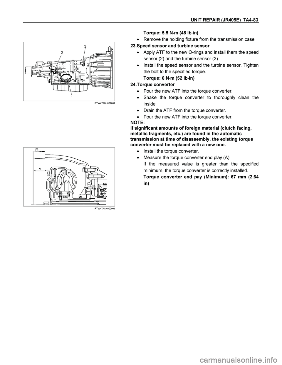
23.Speed sensor and turbine sensor
� Apply ATF to the new O-rings and install them the speed
sensor (2) and the turbine sensor (3).
� Install the speed sensor and the turbine sensor. Tighten
the bolt to the specified torque.
Torque: 6 N�
�� �m (52 Ib�
�� �in)
24.Torque converter
� Pour the new ATF into the torque converter.
� Shake the torque converter to thoroughly clean the
inside.
� Drain the ATF from the torque converter.
� Pour the new ATF into the torque converter.
NOTE:
If significant amounts of foreign material (clutch facing,
metallic fragments, etc.) are found in the automatic
transmission at time of disassembly, the existing torque
converter must be replaced with a new one.
RTW47ASH000901
� Install the torque converter.
� Measure the torque converter end play (A).
If the measured value is greater than the specified
minimum, the torque converter is correctly installed.
Torque converter end pay (Minimum): 67 mm (2.64
in)