Page 3169 of 4264
MANUAL TRANSMISSION 7B1-5
Rear Oil Seal (4�
�� �
2)
Disassembled View
220R300030
Legend
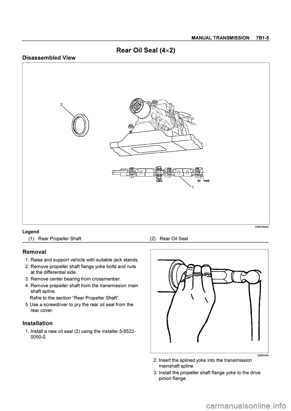
(1) Rear Propeller Shaft (2) Rear Oil Seal
Removal
1. Raise and support vehicle with suitable jack stands.
2. Remove propeller shaft flange yoke bolts and nuts
at the differential side.
3. Remove center bearing from crossmenber.
4. Remove prepeller shaft from the transmission main
shaft spline.
Refre to the section “Rear Propeller Shaft”.
5. Use a screwdriver to pry the rear oil seal from the
rear cover.
Installation
1. Install a new oil seal (2) using the installer 5-8522-
0050-0.
220RS044
2. Insert the splined yoke into the transimission
mainshaft spline.
3. Install the propeller shaft flange yoke to the drive
pinion flange.
Page 3182 of 4264
7B1-18 MANUAL TRANSMISSION
Transmission Case
Major Component
RTW37BLF0005
Legend
(1) Gear Control Box Assembly and Gasket (9) Front Cover (with Oil Seal)
(2) Speedometer Sensor and Driven Gear (10) Top Gear Bearing Snap Ring
(3) Rear Cover Assembly (11) Release Bearing : C24NE
(4) Intermediate Plate with Gear Assembly (12) Shift Fork : C24NE
(5) Transmission Case (13) Fulcrum Bridge : 6VE1
(6) Release Bearing (with Spring) : Diesel engine (14) Release Bearing : 6VE1
(7) Shift Fork : Diesel engine (15) Shift Fork : 6VE1
(8) Counter Front Bearing Snap Ring
Page 3184 of 4264
 from the
transmission case (5) and intermediate plate (4).
14. Remove intermediate plate with gear assembly (4)
from transm")
7B1-20 MANUAL TRANSMISSION
13. Remove the rear cover assembly (3) from the
transmission case (5) and intermediate plate (4).
14. Remove intermediate plate with gear assembly (4)
from transmission case (5).
Reassembly
1. Apply recommended liquid gasket (LOCTITE 17430)
or its equivalent to the transmission case (5),
intermediate plate (4) and rear cover (3) fitting
surfaces.
2. Install the intermediate plate with gear assembly (4)
to the transmission case (5).
Pull out the top gear shaft until the ball bearing snap
ring groove protrudes from the transmission case
front cover fitting face.
Avoid subjecting the main shaft to sudden shock or
stress.
3. Install the rear cover with oil seal (3) on the
intermediate plate with gear (4) by performing the
following steps.
�
Cover the shaft splines with adhesive tape.
This will prevent damage to the oil seal lip. 4. Install a new gasket and gear control box assembly
(1).
Install the harness clips and brackets and then
tighten four new gear control box bolts to the
specified torque.
Torque: 20 N�
�� �m (2.0 kg�
�� �m/14 lb�
�� �ft)
261R300004
5. Install the O-ring (4) to the speedometer driven gear
bushing (3).
Install the driven gear to the speedometer driven
gear bushing (3).
6. Install the speedometer driven gear assembly (2) to
the transmission rear cover (3).
Install the plate (1) to the transmission rear cover
(3).
Torque: 15 N�
�� �m (1.5 kg�
�� �m/11 lb�
�� �ft)
Page 3185 of 4264
.
Torque: 27 N�
�� �m (2.8 kg�
�� �m/20 lb�
�� �ft)
225R300001
8. Install top gear bearing snap ring (10) and counter
front")
MANUAL TRANSMISSION 7B1-21
7. Install the speedometer sensor (2).
Torque: 27 N�
�� �m (2.8 kg�
�� �m/20 lb�
�� �ft)
225R300001
8. Install top gear bearing snap ring (10) and counter
front bearing snap ring (8).
�
Use a pair of snap ring pliers to install the snap
rings to the mainshaft and countershaft.
�
The snap rings must be fully inserted into the
bearing snap ring groove.
9. Front cover with oil seal (9).
Front Cover Oil Seal Replacement
�
Remove the oil seal from the front cover.
�
Apply engine oil to a new oil seal outer
circumference.
�
Apply recommended grease to the oil seal lip.
�
Use the oil seal installer 5-8840-0026-0 to install
the oil seal to the front cover.
220R3000020
10. Install a new gasket and front cover (9) to the
transmission case.
NOTE: Take care not to damage the oil seal.
Notes When Tightening the Bolt:
�
After cleaning the bolt hole, dry it thoroughly with air.
�
After cleaning the screw face of a removed bolt or
new one, dry it thoroughly. Apply recommended
liquid gasket (LOCTITE 242) or its equivalent before
tightening it.
Tighten six front cover bolts to the specified torque.
Torque: 25 N�
�� �
m (2.6 kg�
�� �
m/19 lb�
�� �
ft)
11. Apply molybdenum disulfide type grease to the
areas as shown in the figure and install shift fork (7).
(Diesel engine, C24NE)
F07L100026
Page 3190 of 4264
 and
rev-5th shift rod (5).
� Apply oil to the reverse inhibitor inner surface.
� Install the")
7B1-26 MANUAL TRANSMISSION
Reassembly
1. Install rev-5th shift arm and reverse inhibitor (6) and
rev-5th shift rod (5).
� Apply oil to the reverse inhibitor inner surface.
� Install the shift rod in the intermediate plate (12).
�
Hold a round bar against the shift rod end lower
face to protect it against damage.
� Install a new spring pin.
Never reinstall the used spring pin.
�
Install the interlock pin (11) in the intermediate
plate (12).
Do not allow the interlock pin to fall from the
intermediate plate (12).
2. Install 1st-2nd shift arm (10) and 3rd-4th shift arm(9)
to intermediate plate and gear assembly (12).
3. Install 3rd-4th shift rod (8) and 1st-2nd shift rod (7).
�
Install the interlock pin (11) in the intermediate
plate and gear assembly (12).
�
Install the 3rd-4th shift rod (8) in the intermediate
plate (12).
Do not allow the interlock pin to fall from the
intermediate plate.
�
Install the interlock pin (11) and then 1st-2nd
shift rod (7) in the intermediate plate (12).
Do not allow the interlock pin to fall from the
intermediate plate.
�
Hold a round bar against the shift rod end lower
face to protect it against damage.
� Install a new spring pin.
Never reinstall the used spring pin.
230RS007
4. Install spring (4).
5. Put detent balls (3) in the intermediate plate holes.
�
Apply oil to the detent balls.
6. Install detent springs (2) and detent spring plate and
gasket (1).
�
Install a new gasket and the detent spring plate.
�
Tighten the detent spring plate bolts to the
specified torque.
Torque: 25 N�
�� �m (2.5 kg�
�� �m/18 lb�
�� �ft)
220RS030
Legend
(1) Warped
Page 3197 of 4264
MANUAL TRANSMISSION 7B1-33
6. Mesh the 1st-2nd and 3rd-4th synchronizers with
both the 1st and 3rd gears (double engagement).
226RS015
This will prevent the mainshaft from turning.
7. Install the new mainshaft hub nut.
Use the mainshaft nut wrench 5-8840-2156-0 to
tighten the mainshaft nut (23) to the specified
torque.
Torque: 137 N�
�� �m (14 kg�
�� �m/101 lb�
�� �ft)
226RW214
8. Use a punch to stake the mainshaft nut (23).
226RW153
9. Install needle bearing (22), 5th block ring (21), and
5th gear (20).
10. Apply engine oil to the counter reverse gear (19) and
the reverse gear (26).
Install the counter reverse gear (19) to the counter
shaft.
The reverse gear projection must be facing the
intermediate plate.
226RW151
Page 3198 of 4264
 to the counter shaft.
226RS019
12. Install ball bearing (17) and bearing snap ring (16)
by performing the following steps:")
7B1-34 MANUAL TRANSMISSION
11. Install the counter 5th gear (18) to the counter shaft.
226RS019
12. Install ball bearing (17) and bearing snap ring (16)
by performing the following steps:
�
Select the snap ring which will provide the
minimum clearance between the ball bearing
and the snap ring.
226RS020
�
There are six snap ring sizes available.
The snap rings are color‐coded to indicate
their thickness.
226RS021
Ball Bearing and Snap Ring Clearance
Standard: 0 - 0.15 mm (0 - 0.0059 in)
Snap Ring Availability
Thickness Color Coding
1.1 mm (0.043 in) White
1.2 mm (0.047 in) Yellow
1.3 mm (0.051 in) Blue
1.4 mm (0.055 in) Pink
1.5 mm (0.059 in) Green
1.6 mm (0.063 in) Brown
�
Use a pair of snap ring pliers to install the snap
ring(13) to the counter gear shaft.
The snap ring must be fully inserted into the
counter gear shaft snap ring groove.
13. Assemble reverse idler shaft (15), reverse idler gear
(14), thrust washer (13), and idle shaft pin (12) into
reverse idler gear assembly (11).
The trust washer should be assembled as oil groove
faces to gear side.
Page 3200 of 4264
7B1-36 MANUAL TRANSMISSION
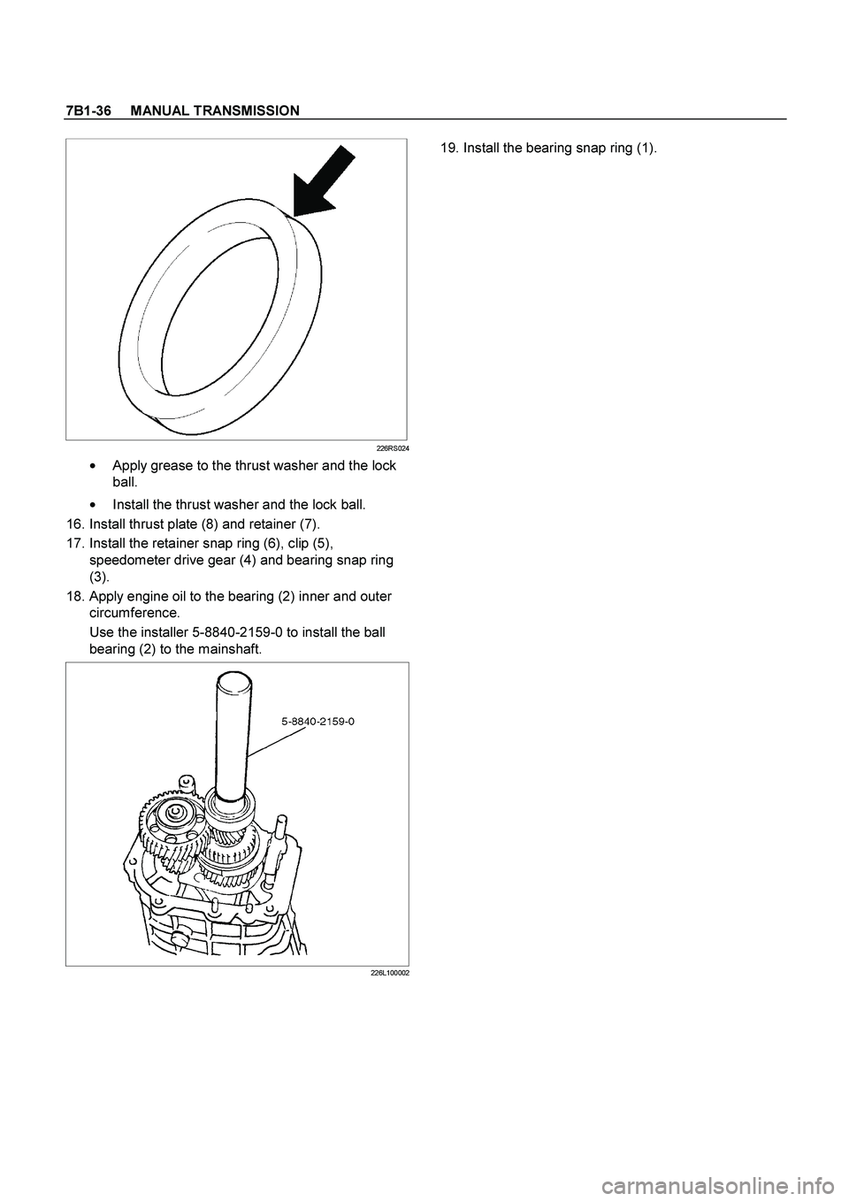
226RS024
�
Apply grease to the thrust washer and the lock
ball.
�
Install the thrust washer and the lock ball.
16. Install thrust plate (8) and retainer (7).
17. Install the retainer snap ring (6), clip (5),
speedometer drive gear (4) and bearing snap ring
(3).
18. Apply engine oil to the bearing (2) inner and outer
circumference.
Use the installer 5-8840-2159-0 to install the ball
bearing (2) to the mainshaft.
226L100002
19. Install the bearing snap ring (1).
 Gear Control Box Assembly and Gasket (9) Front Cover (with Oil Seal)
(2) Speedometer Sensor and Dri")
.
226RS015
This will prevent the mainshaft from turning.
7.")