Page 3822 of 4264
7A4–14 UNIT REPAIR (AW30–40LE)
10. Install the solenoid wiring.
Coat a new O-ring with ATF, and install it to the
solenoid wiring.
Insert the solenoid wiring to the case and install the
stopper plate.
Connect the connectors to the solenoid S1 (1), S2
(2), lock-up solenoid (3), and pressure control
solenoid (4).
24 9RY 0 0011
24 9RY 0 001 2
11. Install a new oil strainer assembly with gaskets.
24 4RY 0 0002
Install the oil strainer with the gaskets to the valve
body. Tighten the four bolts.
Torque: 10 N·m (87lbin)
24 4RY 0 0003
Page 3823 of 4264
UNIT REPAIR (AW30–40LE) 7A4–15
12. Install the oil pan.
Install two magnets in oil pan.
Remove any gasket material and be careful not to
drop oil on the contacting surfaces of the
transmission case and oil pan.
Apply liquid gasket (TB1281 or its equivalent) to the
oil pan as shown in the figure.
NOTE: Install the oil pan as soon as the seal gasket is
applied.
24 0RY 0 001 9
Install and tighten the nineteen bolts.
24 0RY 0 002 0
Torque: 7.4 N·m (65lb in)
Page 3841 of 4264
UNIT REPAIR (AW30–40LE) 7A4–33
Install and tighten the two bolts.
Torque: 25 N·m (19lbft)
25 2RY 0 000 4
26. Check end of output shaft.
Using a dial indicator, measure the end play of the
output shaft by hand.
End play: 0.27 – 0.86 mm (0.0106 – 0.0339 in)
24 7RY 0 002 0
27. Install the (flat ring) 4.0 mm (0.157 in) thick flange
with the rounded edge side of the flange facing the
disc.
Alternately install four discs and four plates. (Disc
first)
25 2RY 0 0009
28. Install the (stepped ring) flange with the flat side of
the flange facing the disc.
Install the snap ring.
Snap ring (Reference)
24 6RY 0 0001
Inside diameter 167.9 mm (6.61 in)
Page 3844 of 4264

7A4–36 UNIT REPAIR (AW30–40LE)
34. Install the overdrive planetary gear and direct clutch.
2 52L10 000 1
35. Coat the assembled bearing and race with
petroleum jelly and install it onto the direct clutch.
Bearing and race diameter (Reference)
2 52L10 001 8
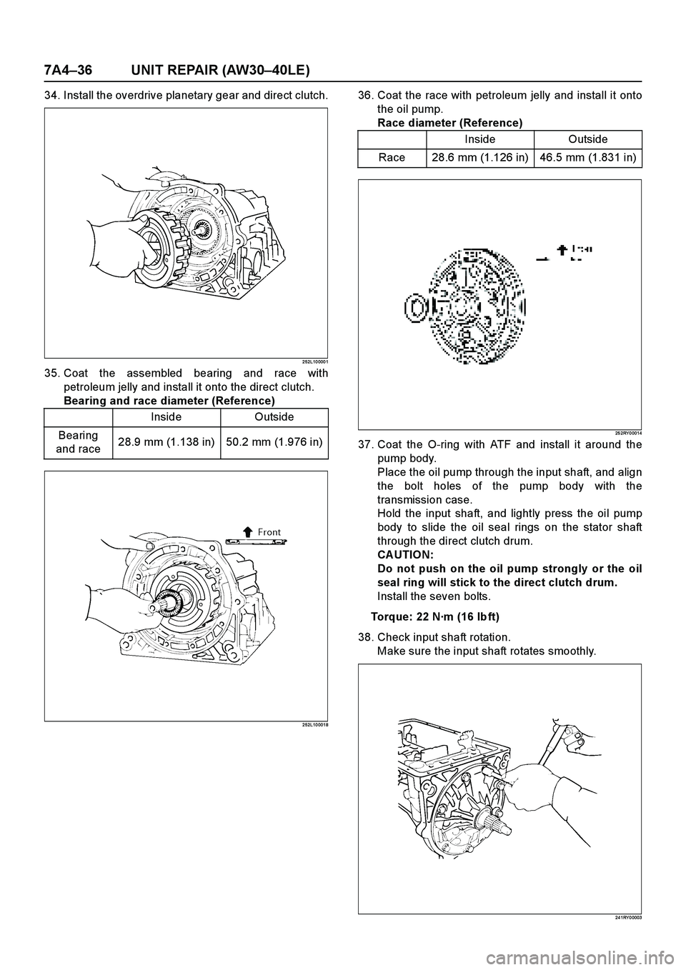
36. Coat the race with petroleum jelly and install it onto
the oil pump.
Race diameter (Reference)
25 2RY 0 0014
37. Coat the O-ring with ATF and install it around the
pump body.
Place the oil pump through the input shaft, and align
the bolt holes of the pump body with the
transmission case.
Hold the input shaft, and lightly press the oil pump
body to slide the oil seal rings on the stator shaft
through the direct clutch drum.
CA UTION:
Do not push on the oil pump strongly or the oil
seal ring will stick to the direct clutch drum.
Install the seven bolts.
Torque: 22 N·m (16 lb ft)
38. Check input shaft rotation.
Make sure the input shaft rotates smoothly.
24 1RY 0 0003
Inside Outside
Bearing
and race28.9 mm (1.138 in) 50.2 mm (1.976 in)
Inside Outside
Race 28.6 mm (1.126 in) 46.5 mm (1.831 in)
Page 3846 of 4264
7A4–38 UNIT REPAIR (AW30–40LE)
Oil Pump
Disassembly View
2 41R20 0003
E nd O FCallo ut
Disassembly
1. Use torque converter as work stand.
Remove 2 oil seal rings from stator shaft.
24 1RY 0 0005
Legend
(1) Oil seal ring
(2) O-ring
(3) Stator shaft(4) Oil pump drive gear
(5) Oil pump driven gear
(6) Oil pump body
Page 3849 of 4264
UNIT REPAIR (AW30–40LE) 7A4–41
Reassembly
1. Place the oil pump body on the torque converter.
2. Coat the driven gear and drive gear with ATF.
3. Install the driven gear and drive gear.
24 1RY 0 001 4
4. Align the stator shaft with the bolt holes.
Tighten the thirteen bolts.
Torque: 10 N·m (87Ibin)
24 1RY 0 000 6
5. Install the oil seal ring.
Coat the oil seal rings with ATF.
Contract the oil seal rings as shown, and install
them onto the stator shaft.
NOTE: Do not spread the ring ends too much.
24 1RY 0 0015
6. Coat a new O-ring with ATF and install it to the oil
pump body.
O-ring size (Reference)
24 1RY 0 0016
Inside diameter 204.9 mm (8.067 in)
Thickness 3.5 mm (0.138 in)
Page 3850 of 4264
7A4–42 UNIT REPAIR (AW30–40LE)
7. Check oil pump drive gear rotation.
Make sure the drive gear rotates smoothly when
installed to the torque converter.
24 1RY 0 001 7
Page 3852 of 4264
7A4–44 UNIT REPAIR (AW30–40LE)
Disassembly
1. Check operation of one-way clutch.
Hold the OD direct clutch drum and turn the input
shaft.
The input shaft should turn freely clockwise and
should lock counterclockwise.
RUW 37A SH00 450 1
2. Remove OD direct clutch assembly from OD
planetary gear assembly.
2 52L10 000 4
3. Then remove thrust bearing with the race from OD
direct clutch drum.4. Check piston stroke of OD direct clutch (C–0).
Place the oil pump onto the torque converter, and
then place the OD direct clutch assembly onto the
oil pump.
25 2L10 0005Use a dial indicator, measure the OD direct clutch
piston stroke applying and releasing the
compressed air (390 – 780 kPa or 57 – 114 psi) as
shown.
Piston stroke: 1.85 – 2.15 mm (0.0728 – 0.0846 in)
25 2L10 0016